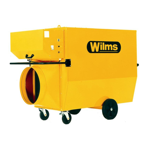
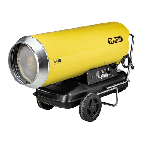
WILMS BV 135 User manual

Perfection is our aim.
Oil Fired Heaters
Operating Manual
BV 135

EC –Declaration of Conformity
according to machine directive 2006 / 42 / EEC
appendix II A
Structure of the machine
Mobile oil-fired heaters ( with and without heat exchanger )
Description:
BV 135
is designed, constructed and manufactured in accordance with the above-mentioned
directive and the low voltage directive 2014 / 35 / EEC and also EMV 2014 / 30 EEC.
The following harmonized standards have been used:
- DIN EN 61000-3-2 EMC Limits for harmonic current emissions
- EN 55011 EMC Requirements
- DIN EN ISO 12100 Safety of machinery
- EN 60335 Safety of electrical machines
- DIN EN ISO 13857 Safety of machinery
Note: The observance of DIN EN ISO 13857 refers only to the protection
against accidental contacts of the fan. For the complete fulfillment of EN 13857
the user resp. installer is responsible.
The following national standards, directives and specifications have been used:
DIN EN 13842 „Mobile oil-fired heaters ( with and without heat exchanger )“
Mönchengladbach 25.06.2014
Managing Director
______________ ______________________ ____________________________
Place, Date Signature Title

Index Type BV 135 Page
Important Notice 1
Functional Characteristics 2
Read carefully before operating 3
Technical Data 4
1 Starting 5
Attention 5
Operation „Heating without room-thermostat“ 5
Operation „Heating with room-thermostat“ 5
Operation with warm air hose 5
2 Stopping 6
Important 6
3 Safety and control devices 6
Room-thermostat 6
4 Cleaning 7
Cleaning of the fuel tank 7
5 Trouble shooting 8
6 Important notice for set-up 9
7 Adjustment of the burner head 10
8 Wiring diagram 11
9 Spare Parts List / Exploded view 12-14

- 1 of 14 -
Important Notice!
1 Use only clean (if possible filtered) Heizöl EL (Diesel)
2 Clean fuel filter regularly
A T T E N T I O N :
Notice: Heizöl EL changes viscosity in low temperature
This heater is standard equipped with a fuel preheating device This
requires also during the heating interruptions (during the night, on
weekends) tension, so it remains effective Therefore, leave the plug
into the socket
When ordering spare parts please give the type, serial number of the
heater and the part number, otherwise a correct delivery is not
possible
The admissible ambient temperature for securing the function of the
control is – 15°C and max + 50°C This is to be especially taken
into consideration whilst drying grain or using the heater outdoors
The heater resp the flame control has to be protected against direct
influence from the bright sun light
Technica specifications are subject to changes without any notice!

- 2 of 14 -
FUNCTIONAL CHARACTERISTICS
The heater is equipped with mounted fuel tank, low-maintenance axial fan,
high pressure spraying burner with automatic flame control, cable with
plug, socket for room thermostat and quintuple filtersystem
Operating System:
The fan runs after starting the heater or in case of heat demand
Fuel is drawn from the tank and pumped into the solenoid valve The solenoid
valve opens and allows fuel to flow to the nozzle The spark between the
electrodes will ignite the atomized fuel The light of the flame activates the
photo-cell and ignition switches off automatically
In case of disturbance or instable burning the flame control switches off
the heater The operation lamp of the burner control flashes A restart
can only be made after reset of the burner controler In case of overheating
of the machine the safety thermostat (STB) switches off and blocks all
functions of the machine
The manual unlocking of the safety thermostat can only be done after
elimination of the fault and cooling of the heater
Switching to position „O“ closes the solenoid valve and the flame is
extinguished The fan will keep running until the cooling cycle is complete

- 3 of 14 -
READ CAREFULLY BEFORE STARTING YOUR HEATER!
Important Notice!
This unit is a space heater with indirect heating, heat exchanger and exhaust
The heater may not be set up near explosive or flamable materials and may not
be used in explosion or fire endangered rooms It may also not be used in areas
with high dust development The heater should be positioned at adequate distance
to flamable material such as wood etc It is essential that there is a sufficient ventilation
of the room The heater may not be worked on or transported during operation
If the heater is used for drying of grain the set-up has to be in a correct angle in front of
the radial fan or alternatively with sufficient distance This has to be done so that the
function of the heater is not influenced by the immense suction of the radial fan
The heater is standard equipped with a fuel pre-heating device This requires also
during the heating interruption (during the night, on weekends) tension so it remains
effective Therefore leave the plug into the socket

- 4 of 14 -
T E C H N I C A L D A T A
Type: BV 135
Voltage V/Hz 230/50
Rated current A 2,43
Nominal capacity kW 0,56
Protection IP 44
Capacity kW 24,8
kcal/h 21 300
Air volume m³ /h 1 500
Pressing max total Pa 100
Max fuel consumption approx kg/h 2,09
(Heizöl EL or Petrolium)
Tank capacity Ltr 40
Dimensions L mm 1250
W mm 490
H mm 690
Weight kg 60
Cone Ø mm 300
Chimney Ø mm 150
Photo cell standard
Thermostat for wet rooms standard
with 10 m cable
Noise level dB (A) 69
(EN ISO 11201)

- 5 of 14 -
1. Starting
Only well instructed persons should start and work with the heater
Before starting the heater check for obvious defaults, proper setting up and as well the
electr supply
a) Ensure a stable set up of the heater
b) Fill the tank with clean Heizöl EL (Diesel)
c) Install exhaust system according to the drawing, see page 10
d) Power supply: Connect heater to the 230 V - 50 Hz power supply
e) Put room thermostat on suitable place in the room and set to desired
temperature (Must be above ambient temperature)
A T T E N T I O N
The heater is standard equipped with a fuel preheating device The function of the
preheating is only given if the heater remains on stand-by with plugged-in electrical
plug for appr 15-20 min before the first starting
During this time the oil is preheated so that the sorting out of paraffine is avoided
During service always obbey the surface temperature from the fuel preheating device
Disconnect the heater first from the power supply and let it cool down (danger of
burning)
Operation "Heating without room thermostat"
Set main switch to position "1"
The automatic heating operation is started when the switch is set to position "1"
The heaters works continuously, the delivered blind plug must be connected with the
thermostat socket
Operation "Heating with room thermostat"
The heater works automatically and depends on the temperature Remove the blind
plug, connect the plug of the room thermostat with the thermostat socket Adjust
required temperature on the room thermostat, turn again main switch to position "1"
Set room thermostat to desired temperature
Operation with warm air hose
The device can be operated with a warm air hose (max length 7 60 m) This is only to
be used in connection with a hose adapter It is essential to ensure proper installation;
reducing the diameter can lead to overheating and shutdown of the device (safety
thermostat)!

- 6 of 14 -
2. Stopping of the heater
Set main switch to pos "O", or reverse the thermostat below the present state
If the heater has been running on position "Heating" (Heizen) it has an automatic
cooling of the heater until it completely shuts off
Important!
Pull the main plug only after the heater has cooled down and stopped
Before repairing or servicing always pull the main plug
3. Safety and contro devices
In case there is no flame - for example caused by lack of fuel - the oil burner relay
shuts off the heater The control lamp on the side of the burner reset button lights up
After the cause of the malfunction has been cleared the reset button can be pushed,
and the burner can be restarted
In case the limit switch has shut off, check the malfunction and eliminate it
(overheating)
After eliminating of the overheating unlock the limit switch by removing the cap on the
right side and pushing the unlocking key (after cooling down of the heater) Then screw
on the protection cap
Room thermostat
The thermostat has a temperature regulation range of 5° C - 30° C and shuts the
burner off after the preset temperature has been reached The fan continues to run
in order to cool the heater down to a temperature of appr 30° C before it stops After
the room temperature drops several °C the heater automatically starts running again

- 7 of 14 -
4. C eaning
The heater should be cleaned minimum once a year including combustion chamber
and burner head Also the fuel filter should be cleaned minimum once a year or even
be changed depending on contamination level
C eaning of the fue tank
If the heater has not been used for a longer period of time and also after each heating
period clean the fuel tank by removing the drain plug on the bottom of the tank
Collect the dirty fuel in an external container
Rinse the fuel tank several times with clean fuel, no dirt particle should remain in the
tank Check the gasket of the drain plug and replace it if necessary, then install the
drain plug again
Fill the tank with the clean fuel (Heizöl) and let the heater burn for 3 minutes, and the
pump will be protected against corrosion
Before repairing or servicing the heater pu the main p ug!
Repair or service of e ectrica components may on y be made by authorized
specia ists!!!

- 8 of 14 -
5. Troub e Shooting
Repairs or service of electrical components may only be made by authorized
specialists!
Fau t Cause Remedy
Main switch on position 1, No electricity Check if there is power
heater does not start
Setting of room Reset thermostat
thermostat The preset
temperature is lower than
the ambient temperature
Safety thermostat Push reset button of
shuts off safety thermostat
Restart heater
Burner starts shortly and Lack of fuel Check oil level in tank
shutts off The red lamp
lights up Air bubbles in the Check fuel suction - and
suction line return line
Control-lamp =
push reset button
On initial start the burner Lack of fuel Push the rest button until
runs shortly and shutts off enough fuel is injected
Air bubbles in the
suction line
There is not enough
fuel
Burner shuts off during Fuel filter dirty Clean (replace) fuel
operation filter
Photo cell dirty Clean the photo cell
carefully
Nozzle dirty or defect Replace nozzle
If your heater does not work properly in spite of these checks, call your nearest
service

- 9 of 14 -
6. Important Notice
These units are oil fired space heaters, equipped with a chimney connection If
connected to a chimney the installation should be made only according to the below
drawing
The connection should be made only with a fixed chimney according to the regulations
or an installed exhaust pipe as shown in the drawing
Never start the heaters connected to just an exhaust pipe which has been lead through
the wall
Use it only with an additional exhaust pipe, minimum above the ridge In case of
horizontal outlet through the wall, use only with T-shaped pipe, refer below drawing
Top of exhaust pipe or chimney
should be 0,5 m above ridge
The horizontally laid exhaust pipe up to the actual chimney must be installed with a
slope of at least 10%

- 10 of 14 -
7. Adjustment of the burner head
Measure A 4 mm
Measure B 2 mm
Measure C 0 mm
Measure D 9 mm
Measure E Between 2 and 3 (for approx. 12 % CO )
Burner Nozzle Danfoss 0,50 usgal/h 80° S
Pump Pressure 12 bar
Adjustment of the ignition e ectrode
E

- 11 of 14 -
8. Wiring Diagram BV 135
Legend
NK = Thermostat - Fan THZ = Tank Heating
F = Photocell RT = Socket for thermostat
STB = Safety Thermostat BA = Controler - lower part
MV = Solenoid Valve HR = Relays
ZT = Ingnition Transformer S = Switch
M = Motor C = Condensor
THT = Thermostat Tank Heating F1 = Fuse

- 12 of 14 -
9. Spare Parts List
From machine no. 46-0001
Pos. Order-No. D E S C R I P T I O N Qty.
01 6162340 Cover 01
02 6162341 Fan Guard 01
03 6162318 Fan Housing 01
04 6162319 Fan 01
05 6162405 Engine 01
07 3308072 Coupling Motor-Pump 01
08 3309764 Pump 01
09 3300064 Nipple 1/4" x 7 mm 01
11 3308074 Solenoid Valve 01
12 6163416 Elbow 01
13 6162406 Condenser 01
14 6162407 Ring 02
15 6162475 Copper Connection 01
16 6162409 Elbow 01
18 6162302 Electrode 01
19 6162476 Slide 01
21 6162303 Nozzle Holder 01
22 6162308 Baffle Plate 01
23 6162479 Nozzle 01
24 6162301 Burner Head 01
25 6162734 Flame Control 01
26 6162417 Bracket 01
27 6162418 Thermostat 01
28 6162419 Bracket 01
29 6162323 Combustion Chamber 01
31 6162422 Lead Through 01
32 6162423 Lead Through 02
33 6162424 Cable with Plug 01
34 6162331 Ignition Transformer 01
35 6162426 Strip Terminal 01
37 6162481 Strain Relief Bushing 01
38 6162428 Switch 01
39 6162808 Quick Coupling for Room Thermostat 01
41 6160160 Jumper 01
42 6162430 Contactor 01
43 6163035 Control Box 01
44 6162342 Housing Bottom 01
46 6162432 Sustainer 01
47 6162343 Side Part - Right 01
48 6162344 Side Part - Front/Back 02
49 6162345 Side Part - Left 01
50 6162436 Fuel Filter 01
51 6162490 Tank Cap 01
52 6162438 Filter 01

- 13 of 14 -
9. Spare Parts List
From machine no. 46-0001
Pos. Order-No. D E S C R I P T I O N Qty.
53 6162346
Fuel Tank 01
54 6162440
Gasket 01
55 6162441
Screw 01
56 6162347
Handle 01
58 6162444
Wheel 02
59 6162445
Ring 02
60 6162446
Cap 02
61 6162447
Fuel Line m
62 6162483
Switch Panel 01
63 6162484
Connecting Pipe 01
66 6162315
Outlet Cone 01
68 1130046
Clamp Hose 02
70 6162304
Burner Cover 01
71 6161318
Safety Thermostat 01
72 6162306
Ignition Cable 02
73 6162454
Cable with Plug 01
74 6162754
Control Box Socket 01
75 6162486
Grommet 01
77 6162300
Spacer 02
78 6162456
Gasket 01
79 6162457
Cleaning Lid 02
806162458
Gasket 02
81 6162348
Plate 01
82 6163450
Condenser 01
83 6162460
Disc 02
87 6162461
Bracket 01
92 6162349
Handle 01
98 6162487
Isolation Plate 01
99 6162488
Fuse 01
100 6162489
Fuse Holder 01
101 6162465
Cover for Pre-Heater 01
102 6162466
Pre-Heater 01

- 14 of 14 -
BV 135 Exploded view
This manual suits for next models
1
Table of contents
Other WILMS Heater manuals