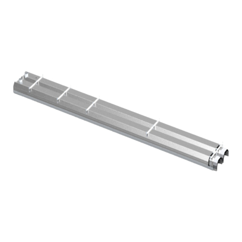
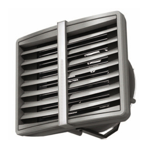
Pakole ACR PRO Installation guide

EN
www.pakole.com
ACR_Pro_008_025_011_210617_V004_EN
(ACR Pro)
ACR Pro 1500H
ACR Pro 2000H
ACR Pro 1500C
ACR Pro 2000C
ACR Pro 1500E
ACR Pro 2000E
ACR PRO – AIR CURTAINS

Acr Pro air curtains Contents
Table of Contents
1. GENERAL AND SAFETY PRINCIPLES �������������������������������������������������������������� 3
2. PURPOSE OF THE DEVICE ��������������������������������������������������������������������������������4
3. BASIC TECHNICAL PARAMETERS ������������������������������������������������������������������� 4
4. DIMENSION���������������������������������������������������������������������������������������������������������5
5. HEAT OUTPUT RANGES������������������������������������������������������������������������������������� 6
6. ASSEMBLY����������������������������������������������������������������������������������������������������������� 7
7. CONTROLLER INSTALLATION������������������������������������������������������������������������ 9
8. ELECTRICAL CONNECTION DIAGRAMS�������������������������������������������������������� 11
9. WATER CONNECTION�������������������������������������������������������������������������������������16
10. OPERATION AND MAINTENANCE ������������������������������������������������������������������� 16
11. SPARE PARTS��������������������������������������������������������������������������������������������������16

3
Acr Pro air curtains Operation and Maintenance Documentation
1. GENERAL AND SAFETY PRINCIPLES
The ACR Pro air curtains are manufactured in compliance with the rules and standards concerning quality, ecology, utility and work com-
fort . Before starting the device be sure to read the Manual carefully.
The ACR Pro air curtains are delivered ready-to-use in a cardboard package that is to protect from any mechanical damages. The pack-
age consists of: the device, the Manual (Operation and Maintenance Documentation) and the Guarantee. If the optional automatic control
ordered, it shall be delivered in a separate package. Make sure all the aforementioned elements are in the package immediately after the
with corrosive air components.
Do not use the curtain in rooms with relative humidity above 80%
Do not leave the curtain ON unattended for longer periods
Do not use the curtain without proper grounding
Do not turn on the curtain with protective cover on
Before conducting any maintenance or cleaning work or during the break in operation for an extended period of time, make sure you
unplug the power cable
To connect the air curtain, use a supply cable with a fork that protects against unintended disconnecting from the power
When the air curtain is connected directly to the cable, please make sure there is a splitter protecting against any undesired discon-
necting
Pay special attention while transporting the device not to damage the casing
When the device is being operated, ensure the safety rules in accordance with the labour standards relating to the operation of any
electrical devices
cable noticed, discontinue the operation immediately
Electricity network, to which the curtain is connected, should be protected against overloading and short circuit
For reasons of serious danger to electric shock disconnect the power supply prior to conducting any repair or maintenance work
Any leakage repairs of the heating medium in the device, of which pipes are under pressure, is strictly prohibited
It is prohibited to connect grounding-type plug to water pipe, gas tubes, lightning conductors, telephone or antenna network
Wait for at least 3 hours before connecting the device to the supply power if the temperature while transporting is below zero
NOTICE!
CAUTION!

Acr Pro air curtains Contents
2. PURPOSE OF THE DEVICE
The industrial air curtain is intended to be used in regions with a moderate and cold climate, in spaces where temperature
ranges from -15 to +40°C and of relative humidity up to 80% (at the temperature of +25°C), in conditions free from external
factors such as pollens, hydrometeor (horizontal precipitation) and chemical vapours.
In winters, air curtains protect against heat loss in rooms which is possible due to the airstream suitably directed that protects
the entrance of cold air into a heated space. In summers, the curtains may be used as cooling devices preventing the entry of
hot air from outside as well as air pollutants.
The ACR Pro industrial air curtains are designed to protect against heat losses in the gateways of buildings of medium and
high capacity especially such as the followings:
warehouse and production halls,
Car showrooms and service stations,
exhibition surfaces
3. BASIC TECHNICAL PARAMETERS
Parameters unit
Curtain with water heater Curtain with electric heater Curtain without heater
ACR Pro 1500H ACR Pro 2000H ACR Pro 1500E ACR Pro 2000E ACR Pro 1500C ACR Pro 2000C
Length of unit m 1,5 2 1,5 2 1,5 2
Max. airow range m7,5 7,5 7,5 7,5 7,5 7,5
Heat output* kW 33 47 14 17,5 - -
Max air output m3/h 6500 9000 6700 9100 6800 9200
Max working pressure MPa 1,6 1,6 - - - -
Diameter of connecon nozzles -3/4” 3/4” - - - -
Motor power supply, consumpon V/Hz/A 230V/50Hz/2,2A 230V/50Hz/3,2A 230V/50Hz/2,2A 230V/50Hz/3,2A 230V/50Hz/2,2A 230V/50Hz/3,2A
Motor power kW 0,5 0,75 0,5 0,75 0,5 0,75
Electric heater power supply, consumpon V/Hz/A - - 400V/50Hz/21A 400V/50Hz/27A - -
Weight lled with water / without water kg 46/44 62/60 45 63 37 51
Noise level dB (A) 59 61 59 61 59 61
Protecon class IP IP 54 IP 54 IP 21 IP 21 IP 54 IP 54

5
Acr Pro air curtains Operation and Maintenance Documentation
4. DIMENSIONS
1500H, 1500E, 1500C
2000H, 2000E, 2000C

6
Acr Pro air curtains Operation and Maintenance Documentation
5. HEAT OUTPUT RANGES
Air curtains with water heater 1500H and 2000H
Air curtains with electric heater ACR Pro 1500E and 2000E
No current on coil surface
Lower temperature on coil surface in comparison to old type of electric heaters (for
ex. electric wires), long life solution
Large space of PTC coil, enhanced energy exchange between coil and air.
No risk of system overheat, thanks to „self cooling” option (coil automatically decreas-
Very low energy consumption
ACR Pro industrial air curtians are equipped with modern and safe solution based on PTC electric heaters.
PTC are thermistors which means that along with the temperature increase the resistance of the heating element increases as well.
ACR Pro 1500H
inlet/outlet water temperature 60/40 70/50 80/60 90/70
inlet air temperature 0 5 10 15 20 0 5 10 15 20 0 5 10 15 20 0 5 10 15 20
Airow: 6500 m3/h
heat output [kW] 18,3 16,2 13,7 11,3 8,6 23,5 21,3 19,1 17,0 14,8 28,0 25,8 23,7 21,5 19,3 32,5 30,4 28,2 26,0 23,8
outlet air temperature [°C] 8,2 12,3 16,2 20,1 23,8 10,6 14,6 18,6 22,6 26,6 12,6 16,6 20,6 24,7 28,7 14,6 18,7 22,7 26,7 30,7
water ow [m3/h] 0,8 0,7 0,6 0,5 0,4 1,0 0,9 0,8 0,8 0,6 1,2 1,2 1,0 0,9 0,9 1,4 1,3 1,3 1,2 1,0
pressure drop [kPa] 2,3 1,8 1,3 0,9 0,9 3,6 3,0 2,4 2,0 1,5 4,9 4,2 3,6 3,0 2,5 6,4 5,7 4,9 4,2 3,6
ACR Pro 2000H
inlet/outlet water temperature 60/40 70/50 80/60 90/70
inlet air temperature 0 5 10 15 20 0 5 10 15 20 0 5 10 15 20 0 5 10 15 20
Airow: 9000 m3/h
heat output [kW] 26,4 23,4 20,4 17,4 14,1 33,3 30,3 27,3 24,3 21,2 39,5 36,5 33,5 30,5 27,5 45,7 42,7 39,7 36,7 33,7
outlet air temperature [°C] 8,6 12,6 16,6 20,6 24,6 10,8 14,8 18,9 22,9 26,9 12,8 16,9 20,9 24,9 28,9 14,8 18,9 22,9 26,9 30,9
water ow [m3/h] 1,2 1,0 0,9 0,8 0,6 1,4 1,3 1,2 1,0 0,9 1,7 1,6 1,5 1,3 1,2 2,0 1,9 1,8 1,6 1,5
pressure drop [kPa] 5,4 4,3 3,3 2,5 1,7 8,1 6,8 5,6 4,5 3,5 11,0 9,5 8,1 6,8 5,6 14,0 13,0 11,0 9,5 8,1

7
Acr Pro air curtains Operation and Maintenance Documentation
6. ASSEMBLY
Before mounting the unit, take into consideration the followings:
access to water and electrical installation
possibility to mount the curtain directly at the gate entrance
It is advisable to mount the device to the wall or the ceiling above the doorway on supporting mount pins or supporting
constructions ( shapes and dimensions of the supporting construction may be individually designed in compliance with durability
and strength requirements).
Pay special attention to proper leveling of the device. If the device is not placed in a horizontal or vertical position, it may result in dam-
aging the fan and consequently malfunctioning of the device. The air inlet and outlet must not be blocked by any objects. While install-
ing the unit, remember to provide easy access to the control panel. A few curtains of the same type may be installed in case of a bigger
doorway. They must be assembled side-by-side to make an uninterrupted stream of air. The curtain is mounted horizontally or vertically
ACR Pro air curtain is advised to be wider (in case of horizontal mounting) or
higher (in case of vertical mounting) than the gate way. If you decide on ACTIVE PROTECTION system, which is the assembly of cur-
tains with water exchanger and without one, you have to mount air curtains with water exchangers on the bottom.
When connecting the curtain, make sure that maintenance work is possible to be conducted. On both connection nozzles manual shut-
inlet connection of the heater to protect it against the torque (that may cause leakage in the heat exchanger).
installed.
-
The ACR Pro multi-purpose connector is designed to connect curtains and to mount curtains to the ceiling (in case of horizontal mount-
ing) or to the wall (in case of vertical mounting). The ACR Pro multi-purpose connector is not included in the content of the delivery and
ACR Pro
multi-purpose connectors may be calculated from the formula below
Horizontal assembly (N – number of curtains)
N x 4 = number of ACR Pro multi-purpose connectors
Vertical assembly (N - number of curtains)
(N x 4) – 2 = number of ACR Pro multi-purpose connectors
Installation of connector inside the curtain Installation of connector at the back of the
curtains

8
Acr Pro air curtains Operation and Maintenance Documentation
To mount the curtain horizontally in a proper way, keep the dis-
tance of min. 300mm from the rear side of the device.
To mount the ACR Pro curtain to the ceiling, use the ACR Pro
multi-purpose connector. Mounting pins of diameter 11 may be
attached to the connector (not included in the delivery).
To mount the curtain vertically make sure the air outlet of the
curtain is as close as possible to the doorway and air gap is at
the height of the upper edge of the entry. Please, make sure to
keep the distance of about 300 mm between the outlet
casing and the wall.
To mount two ACR Pro curtains one above the other, it is neces-
sary to use the ACR Pro multi-purpose connector to install the
curtain to the wall.
To mount ACR Pro-
port, which is used to attach the curtain to the EURO pallet (for
the period of transport). The support is included in the delivery.
rear side as shown in Figure.

9
Acr Pro air curtains Operation and Maintenance Documentation
ACR Comfort is a controller that allows to regulate air speed and desired temperature in the room.
ACR Comfort should be located beyond the air stream generated by the air curtain. The
ACR Comfort allows to regulate 1 pc of ACR PRO unit.
7. CONTROLLER INSTALLATION
Description of the ACR Comfort settings:
ON/OFF
I-II-III – switch for fan speed regulation
HEAT – thermostat sends a signal to the valve and actuator fan and fan turns off when temperature
FAN/COOL – functions not active
ACR Comfort controller
ACR Intelligent controller
protocol.
Functions:
•
•
• AUTO mode is not available for GUARD PRO
•
• or by adjusting air volume automatically).
•
• temperature below critical level 5 ~ 15 °C.
•
•
MODE: Press shortly to select manual or automatic mode.
Press and hold for 3 sec. and select cooling, heating or ventilation mode.
FAN: Press shortly and select fan speed: Low, Med, High or Auto.
ON/OFF INTELLIGENT Panel
10
1
2
3
4 5 6 7 8 9 11 12
1�
2�
3� Anti-freeze indication
4� Automatic programmable mode
5� Manual mode
6� 6 Time Zones for each day
7� Cooling Mode
8� Heating Mode
9� Ventilation Mode
10� Buttons Lock
11�
12�
N L
valve
Fan
N
External NTC
(optional)
High
Med.
Low
Electrical connections:
Technical parameters:
Power supply
Temperature setting range: 5 °C – 40 °C
Temperature working range: -10 °C – 60 °C
IP class: IP 20
Temperature sensor

10
Acr Pro air curtains Operation and Maintenance Documentation
Setting
menu Option Value
1 Temperature calibration -9 °C ~ +9 °C
2 Fan status C1: Thermostatic mode
C2: Continuous mode
3 Temperature sensor 0
1
4 Antifreeze 0: Off
1: On
5 Antifreeze range +5 °C ~ +15 °C
6
0: 2400
1: 9600
2: 19200
7 Modbus ID 1~247 (01~F7)
Button lock
To LOCK buttons, press and hold + and then – and hold both of them for 5 seconds.
To UNLOCK buttons, press and hold + and then – and hold both of them for 5 seconds.
Press MODE:
Change on manual mode or automatic mode .
Hold MODE for 5 seconds:
Change to cool mode , heating mode or ventilation mode .
Press FAN:
Change of the fan speed to low , medium , high or automatic .
Hold FAN for 5 seconds:
BMS Functions:
When Panel Intelligent is switched off, press
and hold MODE for 5 seconds.
To change option use MODE button.
Settings menu
•
•
• Weekly program
• Temperature
• Fan speed
• Heating, ventilation, cool
• Antifreeze mode
Nr� Setting Parameters
1 Working Mode
slave
2 Interface A (+), B (-), 2 wires
3 Baud Rate 2400, 9600, 19200
4 Byte 9 bits in total: 8 data bit + 1 stop bit
5 Modbus RTU Mode
6 Transmission RTU (Remote Terminal Unit) format (please refer to Modbus instruc-
tion)
7 Thermostat
address
1–247: (0 is broadcast address and stand for all thermostat without
response)

11
Acr Pro air curtains Operation and Maintenance Documentation
8. ELECTRICAL CONNECTION DIAGRAMS
To connect the curtain use a 3-core copper cable of minimal diameter 3x1,5mm² for two curtains (up to 6 fans) or 3x2,5mm² for 3 cur-
tains (up to 9 fans). The electrical installation and connection to power supply must be done in compliance with the existing regulations
and standards for building industry.
The electric network, to which the device is to be connected, should protect the device against overloading and short circuit. It is neces-
sary to use protective grounding. Any electrical installation works and the connection to supply power must be conducted in accordance
with the applicable building regulations and standards. The connection of the unit to the power supply must be conducted by a qualified
and a main switch are not included in the set.
-
ment the door is being opened the ACR Pro curtain starts operating accordingly to the parameters set in the control panel of the device.
Fan wiring description:
PE (yellow/green): earth protection
U3 (red): low speed
U2 (grey): middle speed
U1 (brown): high speed
N (blue): Null
Before making the electrical connection, make sure that the mains voltage and mains frequency correspond to the values
indicated on the rating plate of the appliance�
Do not start the appliance without connecting the earth-ground!
Electrical connection for ACR Pro E (PTC electric heat exchanger)
2
2
The Multi 6 control box allows to connect and control up to 6x ACR Pro 2000 and 6x servomotors. The control of the unit motors is via
boxes.

12
Acr Pro air curtains Operation and Maintenance Documentation
8.1 Connection scheme for 1 unit ACR Pro H or C type with Comfort controller
ACR Pro E
8.2 Connection scheme for 1 unit ACR Pro E type with Comfort controller
ACR Pro

13
Acr Pro air curtains Operation and Maintenance Documentation
8.3 Connection scheme for ACR Pro H or C type with custom controller
8.4 Connection scheme for ACR Pro E type with custom controller
ACR Pro
ACR Pro
ACR Pro E
ACR Pro E

14
Acr Pro air curtains Operation and Maintenance Documentation
8.5 Connection scheme for 6 unit ACR Pro H or C type with Multi 6 and Comfort
ACR Pro
ACR Pro
ACR Pro ACR Pro
ACR Pro ACR Pro
ACR Pro
ACR Pro

15
Acr Pro air curtains Operation and Maintenance Documentation
8.6 Connection scheme for 6 unit ACR Pro E type with Multi 6 and Comfort
ACR Pro E
ACR Pro
ACR Pro E ACR Pro E
ACR Pro E ACR Pro E
ACR Pro E
ACR Pro E

16
Acr Pro air curtains Operation and Maintenance Documentation
10. OPERATION AND MAINTENANCE
The engine and fan used in the ACR Pro air curtains are maintenance-free devices but regular check-ups are advised, especially mo-
been used for a longer period of time, unplug it before the next use.
The heat exchanger is not equipped with any anti-freeze protection device. The heat exchanger may be damaged if the room
temperature goes below 0°C.
system. Anti-freeze liquid must be appropriate for the material the exchanger is made of (copper), as well as other elements of the hy-
-
-
9. WATER CONNECTION
11. SPARE PARTS
Fan
1 pcs. PTC panel
Hot water exchanger
(1500 or 2000)
Top cover panel
Contactor
Water connections are located at the back of the unit on the right side. Connections should allow access for service and maintenance
of the exchanger.

PRESERVE THIS WARRANTY
Type:
Date of purchasing::
LIMITED GUARANTEE *
The manufacturer guarantee the costumer that the product and its parts are free from
material and production failures. During normal use the warranty is 2 years. This warranty
The guarantee concerns the costs of laboratory investigations and the parts, which are
needed for proper operation. The delivery and unforeseeable costs belong also to the
mending costs and do not contain compensation costs.
Guarantee mending can only be realized by authorized retailer or service centre.
The guarantee does not concerns the following failures, which are caused by: improper
using,damaging,neglect,accident,lack of maintenance,normal attrition,
-
tion of non-suitable part and mending which is done by not authorized retailer or service
station.
The manufacturer does not assume the responsibility in case of accidentally happened or
directly caused mistake respectively improper using.
Additional guarantee is not accepted�
Guarantee servicing
If your appliance needs guarantee service in that case it can be requested at nearest au-
thorized service station giving in the appliance for repairs.
Mending services
Take the appliance to the nearest authorized service station. If the device is not under guar-
and serial number of device always be at hand.


www.pakole.com
Tel.: +36 22 316 484
Fax.: +36 22 316 074
www.pakole.com
This manual suits for next models
6
Table of contents
Other Pakole Heater manuals

Pakole
Pakole ZENIT 80+ Series User guide

Pakole
Pakole ACR 1000W Installation guide

Pakole
Pakole AIRFUSOR AFR-0 User manual

Pakole
Pakole ACR 100W Installation guide

Pakole
Pakole GHI-11 User manual

Pakole
Pakole GTV-E-20A User manual

Pakole
Pakole LH-30 User manual

Pakole
Pakole GTV-E-20A User manual

Pakole
Pakole ZENIT-12 Series User manual
Popular Heater manuals by other brands

International Thermal Research
International Thermal Research Prospector Installation and operating manual

Sawo
Sawo MX-23NB manual

cecotec
cecotec ReadyWarm 9000 Twin Towel instruction manual

Eldom
Eldom HC120T operating manual

Master
Master B 230 User and Maintenance Book

Mesa Living
Mesa Living 804.167 instruction manual