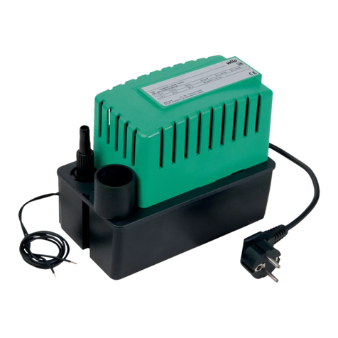
Wilo DrainLift TMP 32-0,5.1 User manual

Wilo-DrainLift TMP 32-0,5.1
Pioneering for You
2044033-Ed.04/2007-05-DDD
D
GB
Einbau- und Betriebsanleitung
Installation and Maintenance Instructions
F
I
Notice de mise en service et de montage
Istruzioni di montaggio, use e manutenzione

Fig. 1
➩

Fig. 2
Fig. 3

Fig. 4
Fig. 5

GB
CE declaration of conformity . . . . . . . . . . . . . 1-2
1. General Information . . . . . . . . . . . . . . . . . . . 8
2. Safety . . . . . . . . . . . . . . . . . . . . . . . . . . . . . . 8
3. Transport and storage . . . . . . . . . . . . . . . . . 9
4. Description of Product . . . . . . . . . . . . . . . . 9
5. Installation . . . . . . . . . . . . . . . . . . . . . . . . . . 10
6. Starting up . . . . . . . . . . . . . . . . . . . . . . . . . . 10
7. Maintenance . . . . . . . . . . . . . . . . . . . . . . . . . 10
8. Problems, Causes and Solutions . . . . . . . . 12
Déclaration de conformité CE . . . . . . . . . . . . . 1-2
1. Généralités . . . . . . . . . . . . . . . . . . . . . . . . . . 13
2. Sécurité . . . . . . . . . . . . . . . . . . . . . . . . . . . . 13
3. Transport et stockage avant utilisation . . . . 14
4. Description du produit . . . . . . . . . . . . . . . . 14
5. Installation/Montage . . . . . . . . . . . . . . . . . . 15
6. Mise en service . . . . . . . . . . . . . . . . . . . . . . 16
7. Entretien . . . . . . . . . . . . . . . . . . . . . . . . . . . . 16
8. Pannes, causes et remèdes . . . . . . . . . . . . 17
CE-Konformitätserklärung . . . . . . . . . . . . . . . 1-2
1. Allgemeines . . . . . . . . . . . . . . . . . . . . . . . . . 3
2. Sicherheit . . . . . . . . . . . . . . . . . . . . . . . . . . . 3
3. Transport und Zwischenlagerung . . . . . . . . 4
4. Beschreibung des Erzeugnissses . . . . . . . 4
5. Aufstellung/ Einbau . . . . . . . . . . . . . . . . . . . 5
6. Inbetriebnahme . . . . . . . . . . . . . . . . . . . . . . 6
7. Wartung . . . . . . . . . . . . . . . . . . . . . . . . . . . . 6
8. Störungen, Ursachen und Beseitigung . . . 7
D F
Dechiarazione CE di conformità . . . . . . . . . . . 1-2
1. Generalità . . . . . . . . . . . . . . . . . . . . . . . . . . . 18
2. Sicurezza . . . . . . . . . . . . . . . . . . . . . . . . . . . 18
3. Transporto e magazzinaggio . . . . . . . . . . . . 19
4. Descrizione del prodotto . . . . . . . . . . . . . . . 19
5. Installazione/Montaggio . . . . . . . . . . . . . . . 20
6. Messa in servizio . . . . . . . . . . . . . . . . . . . . . 21
7. Manutenzione . . . . . . . . . . . . . . . . . . . . . . . . 21
8. Disfunzioni, cause e rimedi . . . . . . . . . . . . . 22
I

DCE-Konformitäts-
erklärung
Hiermit erklären wir, dass
dieses Aggregat folgenden
einschlägigen Bestimmungen
entspricht:
EG-Maschinenrichtlinien
89/392/EWG i.d.F.,
91/368/EWG, 93/44/EWG,
93/68/EWG
Elektromagnetische
Verträglichkeit
89/336/EWG i.d.F.
92/31/EWG, 93/68/EWG
Angewendete harmonisierte
Normen, insbesondere
EN 809, EN 50 081-1,
EN 50 082-1, EN 50 081-2,
EN 50 082-2.
GB EC declaration of
conformity
We hereby declare that this
unit complies with the
following relevant provisions:
EC machinery directive
89/392/EWG in this version,
91/368/EWG, 93/44/EWG,
93/68/EWG
Resistance to
electromagnetism
89/336/EWG in this version
92/31/EWG, 93/68/EWG
Applied harmonized
standards in particular:
EN 809, EN 50 081-1,
EN 50 082-1, EN 50 081-2,
EN 50 082-2.
FDéclaration de
conformité CE
Par la présente, nous
déclarons que cet
agrégat sitisfait aux
dispositions suivantes:
Directives CEE relatives
aux machines 89/392/CEE,
91/368/CEE, 93/44/CEE,
93/68/CEE
Compatibilité
électromagnétique
89/336/CEE, 92/31/CEE,
93/68/CEE
Normes utilisées
harmonisées, notamment
EN 809, EN 50 081-1,
EN 50 082-1, EN 50 081-2,
EN 50 082-2.
NL EG-verklaring van
overeenstemming
iermede verklaren wij dat
deze machine voldoet aan
de volgende bepalingen:
EG-richtlijnen betreffende
machines 89/392/EEG,
91/368/EEG, 93/44/EEG,
93/68/EEG
Elektromagnetische
tolerantie
89/336/EEG, 92/31/EEG,
93/68/EEG
Gebruikte geharmoniseerde
normen, in het bijzonder
EN 809, EN 50 081-1,
EN 50 082-1, EN 50 081-2,
EN 50 082-2.
EDeclaración de
conformidad CE
Por la presente declaramos
que esta unidad satisface las
disposiciones pertinentes
siguientes:
Directivas CE sobre
máquinas 89/392/CEE,
91/368/CEE, 93/44/CEE,
93/68/CEE
Compatibilidad electro-
magnética 89/336/CEE,
92/31/CEE, 93/68/CEE
Normas armonizadas
utilizadas particularmente
EN 809, EN 50 081-1,
EN 50 082-1, EN 50 081-2,
EN 50 082-2.
IDichiarazione di
conformità CE
Con la presente si dichiara
che le presenti pompe sono
conformi alle seguenti
direttive di armonizzazione
Direttiva Macchine CEE
89/392/CEE, 91/368/CEE,
93/44/CEE, 93/68/CEE
Compatibilità
elettromagnetica
89/336/CEE, 92/31/CEE,
93/68/CEE
Norme armonizzate
applicate, in particolare
EN 809, EN 50 081-1,
EN 50 082-1, EN 50 081-2,
EN 50 082-2.
SF CE-standardinmukai-
suusseloste
Ilmoitamme täten, että tämä
laite vastaa seuraavia
asiaankuuluvia määräyksiä:
EY-konedirektiivit
89/392/ETY, 91/368/ETY,
93/44/ETY, 93/68/ETY
Sähkömagneettinen
soveltuvuus
89/336/ETY, 92/31/ETY,
93/68/ETY
Käytetyt yhteensovitetut
standardit, erityisesti
EN 809, EN 50 081-1,
EN 50 082-1, EN 50 081-2,
EN 50 082-2.
SEEC konformitets-
deklaration
Härmed förklaras att denna
maskin uppfyller följande
bestämmelser:
EEC maskindirektiv
89/392/EEC i denna version,
91/368/EEC, 93/44/EEC,
93/68/EEC
Elektromagnetisk
kompatibilitet 89/336/EEC i
denna version, 92/31/EEC,
93/68/EEC
Tillämpade harmoniserade
normer, särskilt:
EN 809, EN 50 081-1,
EN 50 082-1, EN 50 081-2,
EN 50 082-2.
HEK. azonossági
nyilatkozat
Ezennel kijelentjük, hogy
az agregát a megkívánt
alanti feltételeknek
megfelel:
EK-Gépirányelvek
89/392/EWG, 91/368/EWG,
93/44/EWG, 93/68/EWG
Elektromagnetikus
ÖsszeegyeztethetŒség
89/336/EWG, 92/31/EWG,
93/68/EWG
Alkalmazott, harmonizált
normák, különösen az
EN 809, EN 50 081-1,
EN 50 082-1, EN 50 081-2,
EN 50 082-2.
1

TR Uygunluk Belgesi
As¸agˇí´daki cihazlarí´n
takibi standartlara vygun
oldugˇ unu temin
ederiz:
AB-Makina Standartlari
89/392/EWG i.d.F.,
91/368/EWG, 93/44/EWG,
93/68/EWG
Elektromanyetik
Uyumluluk
89/336/EWG i.d.F.,
92/31/EWG, 93/68/EWG
Özellikle kullaní´lan Normlar
EN 809, EN 50 081-1,
EN 50 082-1, EN 50 081-2,
EN 50 082-2.
GR ∆ήλωση συµµρφωσης
µε τους κανονισµούς CE
∆ηλώνουµε τι το προϊν
αυτ ικανοποιεί τις
ακλουθες διατάξεις:
Οδηγίες CEE σχετικά
µε µηχανήµατα
89/392/CEE, 91/368/CEE,
93/44/CEE, 93/68/CEE
Ηλεκτροµαγνητική
συµβαττητα
89/336/CEE, 92/31/CEE,
93/68/CEE
Εναρµονισµένα
χρησιµοποιούµενα
πρτυπα, ιδιαίτερα
EN 809, EN 50 081-1,
EN 50 082-1, EN 50 081-2,
EN 50 082-2.
CZ Osvûdãení o shodnosti s
normami EU
Prohla‰ujeme tímto, Ïe toto
zafiízení odpovídá následujícím
pfiíslu‰n˘m ustanovením:
Smûrnice o strojírenském
zafiízení ES 89/392/EHS
vãetnû dodatkÛ,
91/368/EHS, 93/44/EHS,
93/68/EHS
Elektromagneticá sná‰en-
livost 89/336/EHS vãetnû
dodatkÛ, 92/31/EHS,
93/68/EHS
PouÏité souhlasné normy,
zejména:
EN 809, EN 50 081-1,
EN 50 082-1, EN 50 081-2,
EN 50 082-2.
PL OÊwiadczenie zgodnoÊci EC
Niniejszym oÊwiadczamy, ˝e
pompa odpowiada nast´pujà-
cym w∏aÊciwym dla niej
dyrektywom:
Wytyczne dla przemys∏u
maszynowego EC
89/392/EEC w tej wersji,
91/368/EEC, 94/44/EEC,
93/68/EEC
OdpornoÊç elektro-
magnetyczna EC
89/336/EEC w tej wersji,
92/31/EEC, 93/68/EEC
Zastosowano normy
zharmonizowane, w
szczególnoÊci:
EN 809, EN 50 081-1,
EN 50 082-1, EN 50 081-2,
EN 50 082-2.
RUS
Zaåvlenie o sootvetstvii
normam, dejstvuœwim v
Evropejskom Soob-westve
Nastoåwim dokumentom
zaåvlåem, hto dannaå
ustanovka sootvetstvuet
sleduœwim postanovleniåm:
Direktivy ES
otnositelæno maπin i
stankov 89/392/CEE,
91/368/CEE, 93/44/CEE,
93/68/CEE
Qlektromagnitnaå
sovmestimostæ
89/336/CEE, 92/31/CEE,
93/68/CEE
Ispolæzovavπieså
garmonizirovannye
standarty i normy, v
hastnosti
EN 809,
EN 50 081-1, EN 50 082-1,
EN 50 081-2, EN 50 082-2.
DK EF-overensstemmelses-
erklæring
Det erklæres hermed, at dette
udstyr er i overensstemmelse
med følgende bestemmelser:
EU maskindirektiver:
89/392/EØF i denne
udgave, 91/368/EØF,
93/44/EØF, 93/68/EØF
Elektromagnetisk
kompatibilitet:
89/336/EØF i denne
udgave, 92/31/EØF,
93/68/EØF
Anvendte harmoniserede
normer, især:
EN 809, EN 50 081-1,
EN 50 082-1, EN 50 081-2,
EN 50 082-2.
NEU-overensstemmelses-
erklæring
Det erklæres herved at
dette utstyret stemmer
overens med følgende
bestemmelser:
EU-direktiver for maskiner
89/392/EEC og følgende,
91/368/EEC, 93/44/EEC,
93/68/EEC
Elektromagnetisk
kompatibilitet
89/336/EEC og følgende,
92/31/EEC, 93/68/EEC
Anvendte harmoniserte
normer, i særdeleshet
EN 809, EN 50 081-1,
EN 50 082-1, EN 50 081-2,
EN 50 082-2.
WILO GmbH
Nortkirchenstraße 100
44263 Dortmund · Germany
2011678.3
Quality Management
2
WILO AG
Nortkirchenstraße 100
Quality Management 44263 Dortmund · Germany

DEUTSCH
3
Bedienungshinweise für den
Betreiber
Das Lesen der Bedienungshinweise erleichtert
Ihnen die Bedienung der Schmutzwasser-Hebe-
anlage und das Verstehen der Arbeitsabläufe.
Wir sind aber auch verpflichtet, Sie auf die
Beachtung der in der gesamten Einbau- und
Betriebsanleitung beschriebenen Sicherheitshin-
weise aufmerksam zu machen.
Einstellungen, Wartungsarbeiten sowie Reparatu-
ren sollten Sie dem Fachhandwerk oder dem Wilo-
Kundendienst überlassen.
Die Funktionen der Anlage laufen automatisch ab.
Eine Bedienung ist nicht erforderlich.
1 Allgemeines
Einbau und Inbetriebnahme nur durch Fach-
personal!
1.1 Verwendungszweck
Automatisch arbeitende Schmutzwasser-Hebe-
anlage zur Entsorgung von Duschen, Wasch-
becken, Wasch-/Geschirrspülmaschinen in Alt-
und Neubauten, deren Schmutz-/Abwässer nicht
mit natürlichem Gefälle dem Kanalsystem zugeführt
werden können und deshalb über die Rück-
stauebene angehoben werden müssen. Die Anlage
ist besonders geeignet für die Entsorgung von
Waschmaschinen und Duschen in Kellerräumen.
Schmutzwasser-Hebeanlagen zur Förderung von
fäkalien- und faserfreien, nicht aggressiven
Schmutzwässern.
Für den Einsatz der Anlage sind grundsätzlich die
Normen DIN EN 12050-2, DIN EN 12056 sowie die
DIN 1986-100 einzuhalten.
Die Hebeanlage ist nicht geeignet zur Förderung
von fäkalienbelasteten Abwässern.
1.2 Anschluß- und Leistungsdaten
– Maximale Fördermenge: 4,5 m3/h
– Maximale Förderhöhe: 6,5 m
– Max. Fördermedien-Temp.: 45 °C im Dauer-
betrieb, kurzzeitig
auch Abwässer aus
Geschirrspül- und
Waschmaschinen
bis max. 75°C
– Feststoff-Korngröße max.: 10 mm
– Spannung / Frequenz: 1~230 V, 50 Hz
– Aufnahmeleistung: 0,33 kW
– Nennstrom: 1,5 A
– Betriebsart: Dauerbetrieb S1
nach DIN, VDE
0530 T1
– Schutzart: IP 44
– Druckanschluß: DN 32
– Zuläufe: 2 x G 11/2(DN 40)
nach DIN 1986 incl.
Blinddeckel und
Dichtring
– Entlüftung: 25 mm Außen-l
– Abmessungen B x H x T: 511 x 300 x 269 mm
– Nutzvolumen: 12 l
– Gewicht: 7,1 kg
Bei Ersatzteilbestellungen sind sämtliche Daten
des Anlagentypenschildes anzugeben.
2 Sicherheit
Diese Betriebsanleitung enthält grundlegende
Hinweise, die bei Aufstellung und Betrieb zu be-
achten sind. Daher ist diese Betriebsanleitung un-
bedingt vor Montage und Inbetriebnahme vom
Monteur sowie dem zuständigen Betreiber zu le-
sen. Es sind nicht nur die unter diesem Hauptpunkt
Sicherheit aufgeführten allgemeinen Sicherheits-
hinweise zu beachten, sondern auch die unter den
folgenden Hauptpunkten eingefügten, speziellen
Sicherheitshinweise.
2.1 Kennzeichnung von Hinweisen in der
Betriebsanleitung
Die in dieser Betriebsanleitung enthaltenen Sicher-
heitshinweise, die bei Nichtbeachtung Gefähr-
dungen für Personen hervorrufen können, sind mit
dem allgemeinen Gefahrensymbol
,
bei Warnung vor elektrischer Spannung mit
besonders gekennzeichnet.
Bei Sicherheitshinweisen, deren Nichtbeachtung
Gefahren für die Anlage und deren Funktion her-
vorrufen können, ist das Wort
eingefügt.
ACHTUNG!

DEUTSCH
4
2.2 Personalqualifikation
Das Personal für die Montage muß die entspre-
chende Qualifikation für diese Arbeiten aufweisen.
2.3 Gefahren bei Nichtbeachtung der
Sicherheitshinweise
Die Nichtbeachtung der Sicherheitshinweise kann
eine Gefährdung für Personen und Anlage zur
Folge haben. Die Nichtbeachtung der Sicher-
heitshinweise kann zum Verlust jeglicher Scha-
denersatzansprüche führen.
Im einzelnen kann Nichtbeachtung beispielsweise
folgende Gefährdungen nach sich ziehen:
– Versagen wichtiger Funktionen der Anlage,
– Gefährdungen von Personen durch elektrische,
Infektionen auslösende und mechanische Ein-
wirkungen,
– Gefährdungen von Personen und Umwelt durch
Nichtbeachtung von Hygienevorschriften für den
Umgang mit Infektionen auslösenden Medien.
2.4 Sicherheitshinweise für den Betreiber
Die bestehenden Vorschriften zur Unfallverhütung
sind zu beachten.
Gefährdungen durch elektrische Energie sind aus-
zuschließen. Vorschriften des VDE und der ört-
lichen Energieversorgungsunternehmen beachten.
2.5 Sicherheitshinweise für Inspektions- und
Montagearbeiten
Der Betreiber hat dafür zu sorgen, daß alle
Inspektions- und Montagearbeiten von autorisier-
tem und qualifiziertem Fachpersonal ausgeführt
werden, das sich durch eingehendes Studium der
Betriebsanleitung ausreichend informiert hat.
Grundsätzlich dürfen Arbeiten an der Anlage nur im
Stillstand durchgeführt werden.
2.6 Eigenmächtiger Umbau und
Ersatzteilherstellung
Veränderungen der Anlage sind nur nach Ab-
sprache mit dem Hersteller zulässig. Original-
ersatzteile und vom Hersteller autorisiertes
Zubehör dienen der Sicherheit. Die Verwendung
anderer Teile kann die Haftung für die daraus ent-
stehenden Folgen aufheben.
2.7 Unzulässige Betriebsweisen
Die Betriebssicherheit der gelieferten Anlage ist nur
bei bestimmungsmäßiger Verwendung entspre-
chend Abschnitt 1 der Betriebsanleitung gewähr-
leistet. Die im Katalog/Datenblatt angegebenen
Grenzwerte dürfen auf keinen Fall über- oder
unterschritten werden.
3 Transport und
Zwischenlagerung
– Beim Transport ist darauf zu achten, daß die
Anlage keinen Stoßbelastungen ausgesetzt wird.
– Die Anlage ist trocken und frostsicher zu lagern.
4 Beschreibung des Erzeugnisses
4.1 Beschreibung der Anlage
Die automatisch arbeitende Schmutzwasser-
Hebeanlage (Bild 1) besteht aus einem gas- und
wasserdichten Sammeltank aus Kunststoff, der auf
dem Boden (möglichst tief), z.B. unter einem
Waschbecken aufgestellt wird.
Die Anschlüsse für die Entwässerungsstellen (Bild
3, Pos.1/2) sowie für die Druckleitung (Bild 3, Pos.3)
befinden sich auf der Rückseite des Behälters. Der
hinter der Anlage verfügbare Platz ermöglicht eine
einfache Rohrführung. Dadurch lassen sich die
Zuläufe und die Druckleitung von beiden Seiten an-
schließen. Bei mehr als 2 Entwässerungsstellen ist
der Anschluß durch Verzweigung der Zulaufleitung
zu erreichen.
Es ist darauf zu achten, daß nicht aus allen
Entwässerungsstellen gleichzeitig Schmutzwasser
zuläuft.
Die im Behälter eingebaute Pumpe (Bild 1, Pos.1,
Bild 5) taucht bei gefülltem Behälter in das
Abwasser. Der Motor ist wasserdicht gekapselt. Die
Motorwelle ist zweifach gegen den Pumpenraum
abgedichtet.
Die Motorwicklung ist mit einer Überlastsicherung
geschützt, die den Motor bei übermäßiger Be-
anspruchung automatisch abschaltet und nach
Abkühlung automatisch wieder einschaltet.
Der eingebaute Staudruckschalter (Bild 1, Pos.4)
schaltet die Anlage niveauabhängig ein und aus.
Die Be- und Entlüftung des Behälters erfolgt durch
den in der Anlage integrierten Aktivkohlefilter (Bild
1, Pos.5) direkt in den Aufstellungsraum oder über
eine separat anzuschließende Entlüftungsleitung
über Dach. Um zu verhindern, daß bei einem Ausfall
der Pumpe und steigendem Flüssigkeitsstand der
Sammeltank durch den Aktivkohlefilter überläuft,
ist eine zusätzliche Rückschlagklappe (Bild 1,
Pos.6) eingebaut. Der Abflußanschluß enthält
ebenfalls eine Rückschlagklappe (Bild 1, Pos.7).
4.2 Lieferumfang
– Schmutzwasser-Hebeanlage,
– Beipack: Befestigungsschelle, Dichtringe, Über-
wurfmuttern, Druckringe und Blinddeckel
– Einbau- und Betriebsanleitung.

DEUTSCH
5
5 Aufstellung/Einbau
5.1 Montage
– Die Anlage ist in einem frostfreien Raum aufzu-
stellen.
– Die Aufstellungsfläche muß waagerecht und plan
sein.
– Die Hebeanlage und elektrischer Anschluß
(Netzstecker) müssen für Wartungsarbeiten
auch nach der Montage zugänglich bleiben.
– Installationsbeispiel siehe Bild 2.
– Hauptabmessungen der Anlage siehe Bild 3.
– Die Entwässerungsstellen an die Zuläufe (Bild 3,
Pos.1/2) anschließen. Hierzu sind die Überwurf-
mutter, der Druckring und der vorhandene
Dichtring über die Zulaufleitung (Außen-l40
mm, handelsübliches PVC-Rohr) zu schieben.
Das PVC-Rohr in den Zulaufstutzen schieben
und die Überwurfmutter fest auf den Zulauf-
stutzen schrauben. Den Zulauf nicht am Ge-
winde dichten.
Die nicht gebrauchten Zulauföffnungen müssen
mit den mitgelieferten Verschlußkappen ver-
schlossen werden:
– Druckring auf die Verschlußkappe schieben,
– Dichtung (Querschnittsform: dreieckig) mit der
breiten Kante zum Druckring weisend auf-
schieben,
– Verschlußkappe in die Überwurfmutter legen
und auf die Zulauföffnung schrauben.
Die seitlichen Zuläufe (DN 40)
müssen oberhalb des höchst-
möglichen Wasserspiegels (180
mm) liegen. Deshalb muß das
Aufstellungsniveau (Sohle) der
Duschtasse mindestens 180 mm
höher liegen als das Aufstellungs-
niveau der Kleinhebeanlage
(Bild 2). Unter Verwendung einer
Viega-domoplex-Ablaufgarnitur
kann die Höhe der Duschunter-
kante bis auf 110 mm über der
Aufstellebene reduziert werden,
wenn der Abstand zwischen der
Hebeanlage und Dusche gleich
oder größer 1.200 mm ist.
– Die Rückschlagklappe (Bild 4) wird in die untere
Zulauföffnung (Bild 3, Pos.2) bis zum Anschlag
so eingeschoben, daß die Klappe sich zum
Behälter öffnen läßt. Dann, wie oben beschrieben,
die Zulaufleitung einschieben (Die Verwendung
der Klappe ist in Deutschland nicht zulässig.).
ACHTUNG!
– In die Druckleitung wird der Einbau einer
Absperrarmatur empfohlen. Sie muß für
Schmutzwasser geeignet sein und ist bauseits
beizustellen.
– Druckleitung (Bild 2, Pos.1, Mindest-lDN 25
/Anschluß: Bild 3, Pos.3) steigend an die
Sammelleitung anschließen.
– Soll die Druckleitung horizontal verlaufen, muß
sie nach Austritt aus dem Gerät mit einer Schleife
(U-förmiger Geruchsverschluß) verlegt werden.
– Zum Schutz gegen evtl. Rückstau aus dem öf-
fentlichen Kanal ist die Druckleitung als „Rohr-
schleife“ (U-förmig) auszubilden. Sie muß über
der örtlich festgelegten Rückstauebene (meist
Straßenniveau) liegen.
– Soll die Entlüftung nicht durch den im Gerät in-
tegrierten Aktivkohlefilter erfolgen, sondern
durch eine Entlüftungsleitung über Dach, so ist
die Abdeckkappe (Bild 1, Pos.9) über der
Entlüftung zu entfernen und die Entlüftungs-
leitung (Bild 2, Pos.2, Innen-l25 mm, handels-
übliches PVC-Rohr) über ein flexibles
Schlauchstück auf den Stutzen zu schieben. Der
Aktivkohlefilter (Bild 1, Pos.5) kann entfernt wer-
den.
– Die Anlage ist gegen Auftrieb zu sichern. Dazu
die beiliegende Schelle (Bild 1, Pos.15) über den
Zulaufstutzen schieben und am Boden mit
Schrauben und Dübeln befestigen.
5.2 Elektrischer Anschluß
Die Installation der Steckdose ist von
einem beim örtlichen EVU zugelasse-
nen Elektroinstallateur und entspre-
chend den geltenden VDE-Vorschriften
auszuführen.Wenn die Anschlußleitung
dieser Anlage beschädigt ist, muss sie
durch den Kundendienst oder eine
ähnlich qualifizierte Person ersetzt wer-
den.
– Stromart und Spannung des Netzanschlusses
müssen den Angaben auf dem Typenschild der
anzuschließenden Anlage entsprechen,
– Anlage vorschriftsmäßig erden,
– Netzseitige Absicherung: 10A, träge.

DEUTSCH
6
6 Inbetriebnahme
– Schukostecker einstecken,
– Wasser einlaufen lassen bis die Pumpe anläuft,
– Alle Rohrverbindungen auf Dichtigkeit kontrollie-
ren.
7 Wartung
Einwandfreie Funktion und ruhiger Lauf der Pumpe
sollten regelmäßig kontrolliert werden. Damit ist
größeren Störungen vorzubeugen. Die Pumpe
sollte, abhängig von der Zusammensetzung der
Förderflüssigkeit, mindestens einmal jährlich kon-
trolliert und gereinigt werden.
7.1 Wartung und Pflege des Gerätes (Bild 1)
– Wasser einlaufen lassen und Behälter leerpum-
pen,
Vor der Überprüfung der Anlage
Netzstecker ziehen!
– Abdeckhaube (Bild 1, Pos.8) durch Betätigen des
Drehstiftes (Bild 1, Pos.10) und Drücken der 3
Schnapphaken (seitlich und vorne) abnehmen,
– Verunreinigungen an den Behälterwänden be-
seitigen,
– Entlüftungsleitung bzw. Entlüftungsventil reini-
gen, Aktivkohlefilter erneuern,
– Montage in umgekehrter Reihenfolge.
7.2 Demontage der Pumpe (Bild 1)
Spülung, Öffnen des Gerätes sowie Beachtung der
Warnhinweise wie in 7.1 beschrieben,
– 3 Schrauben der Motorbefestigung lösen (Bild 1,
Pos.11),
– Obere Schlauchschelle (Bild 1, Pos.12) des
Abflußanschlusses lösen,
– Verschraubung des Entlüftungsröhrchens (Bild
1, Pos.13) an der Behälterwand lösen und
Entlüftungsröhrchen abziehen.
– PG-Verschraubung des Anschlußkabels (Bild 1,
Pos.14) an der Behälterwand lösen und Kabel
zur Behälterinnenseite durchziehen,
– Falls die Pumpe ganz aus dem Behälter heraus-
genommen werden soll, den Stecker des elektri-
schen Anschlusses abschrauben und das Kabel
aus der gelösten PG-Verschraubung herauszie-
hen,
– Pumpe mit Staudruckschalter und Elektroan-
schluß herausnehmen,
– Reinigen des Staudruckschalters,
– Montage der Bauteile in umgekehrter Reihen-
folge durchführen,
– Probelauf durchführen.
Falls die Pumpe zur Reparatur einge-
schickt werden soll, ist eine benutzte
Anlage aus hygienischen Gründen vor
dem Transport zu entleeren und zu rei-
nigen. Außerdem müssen alle Teile, mit
denen eine Berührung möglich ist, des-
infiziert werden (Sprühdesinfektion). Die
Teile müssen in reißfesten, ausreichend
großen Kunststoffsäcken dicht ver-
schlossen und auslaufsicher verpackt
werden. Sie sind mit bekannten Spe-
diteuren unverzüglich einzusenden.

DEUTSCH
7
8 Störungen, Ursachen und Beseitigung
Störung Ursache Abhilfe
Motor läuft nicht Netzspannung fehlt Hauptsicherungen, FI-Schalter, Netzkabel über-
prüfen
Vorsicherungen defekt Sicherungen wechseln, ggfs. Ursache für
Sicherungsausfall beseitigen
Überlastschalter hat Temp. Fördermedium zu hoch, die zulässigen
ausgelöst Temperaturen einhalten. Bei wiederholtem
Auftreten Kundendienst einschalten
Pumpe blockiert, Kundendienst einschalten
Überlastschalter hat
ausgelöst
Staudruckschalter defekt Kundendienst einschalten
Motor defekt Kundendienst einschalten
Motor läuft, Pumpe Druckleitung verstopft oder Verstopfung bzw. Knicke beseitigen, Probelauf
fördert nicht geknickt durchführen
Schieber in Druckleitung Schieber öffnen
geschlossen
Anlagenentlüftung Entlüftungsrohr abziehen und reinigen bzw.
verstopft Aktivkohlefilter erneuern
Pumpe fördert zu Laufrad verschlissen oder Laufrad reinigen oder ersetzen lassen
wenig verschmutzt
Rohrleitung verstopft Verstopfung beseitigen
Förderhöhe od. Druckver- Leitung mit größerem ø verwenden,
luste zu hoch,
Auslegung fehlerhaft
Pumpe läuft in Entlüftung verstopft Entlüftung reinigen
kurzen Intervallen Rückschlagklappe undicht Säubern bzw. erneuern
Motor dreht mit Fremdkörper im Gerät Pumpe ausbauen und reinigen, ggfs.
großen Lauf- Kundendienst einschalten
geräuschen
Läßt sich die Betriebsstörung nicht beheben, wenden Sie sich bitte an das Fachhandwerk oder
an die nächstgelegene WILO-Kundendienststelle oder Vertretung.
Technische Änderungen vorbehalten!

ENGLISH
8
Safety precautions for the operator
Reading the operating instructions makes it easier
to operate the unit and to understand the operating
sequence.
We are also obliged to draw your attention to the
necessity of adhering to the safety instructions gi-
ven throughout the installation and operation in-
structions.
Adjustments, maintenance work and repairs
should only be carried out by an expert or by Wilo
customer services.
The unit's functions are all automatic. It is not ne-
cessary to service the unit.
1 General Information
Assembly and installation should only be carried
out by qualified personnel!
1.1 Uses
As an automatic sewage water lifting unit for the sa-
nitation of showers, basins, washing machines and
dishwashers in both old and new buildings, whose
dirty or waste water cannot be transported into the
canal system by the natural downward gradiant
and must therefore be lifted above the damming up
level. This unit is particularly suitable for the sani-
tation of washing machines and showers in cellars.
As a waste water lifting unit for the transportation of
sewage and fibre-free, non-aggressive waste wa-
ter.
The norm DIN EN 12050-2, DIN EN 12056 and DIN
1986-100 must be observed when operating the
unit.
This lifting unit is not suitable for transporting waste
water which contains solid sewage.
1.2 Connection and output data
– Max. transporting capacity: 4,5 m3/h
– Maximum lift: 6,5 m
– Max. flow medium temp.: 45°C when in
constant use,
Washing machine
and dishwasher
waste water may
also reach 75°C
for short periods
of time.
– Max. size of grains or solids.: 10 mm
– Voltage / Frequency: 1~230 V, 50 Hz
– Capacity: 0,33 kW
– Nominal current: 1,5 A
– Type of operation: Constant use S1
in acordance with
DIN, VDE 0530 T1
– Protective system: IP 44
– Delivery connection: DN 32
– Supplies: 2 x G 11/2(DN 40)
in accordance
with DIN 1986
incl. blind cover
and sealing ring
– Ventilation: 25 mm outer dia-
meter
– Measurements W x H x B: 511 x 300 x 269
mm
– Useful volume: 12 l
– Weight: 7,1 kg
When ordering spare parts, all details on on the ra-
ting plate should be given.
2 Safety
These instructions contain important information
which must be followed when installing and opera-
ting the pump. It is therefore imperative that they be
read by both the installer and relevant operators
before the pump is assembled and operated. Both
the general safety points in this section and the
more specific safety points in the following sections
should be noted.
2.1 Instruction symbols in this operating ma-
nual
Safety precautions in these operating instructions
which, if not followed, could cause personal injury
are indicated by the symbol:
,
Safety precautions warning of danger due to elec-
tricity are indicated by the symbol:
Safety precautions which, if not followed, could da-
mage the pump or installation and cause it to mal-
function are indicated by the word:
2.2 Staff training
The personnel installing the pump must have the
appropriate qualifications for this work.
ATTENTION!

ENGLISH
9
2.3 Risks incurred by failure to comply with the
safety precautions
Failure to comply with the safety precautions could
result in personal injury or damage to the installa-
tion. Failure to comply with the safety precautions
could also invalidate any claim for damages.
In particular, failure to comply with these safety pre-
cautions could give rise, for example, to the follo-
wing risks:
– the failure of important parts of the installation,
– Personal injury due to electrical, mechanical and
bacteriological causes,
– Personal injury and damage to the environment
due to failure to comply with hygiene regulations
when handling media liable to cause infection.
2.4 Safety precautions for the operator
Current regulations on the prevention of accidents
must be observed.
Injury resulting from electrical charges must be
avoided. The VDE (German association of Electrical
Engineers) and national energy supply company
regulations must be observed.
2.5 Safety information for inspection and as-
sembly
The operator must ensure that all inspection and in-
stallation work is carried out by authorised and
qualified specialists who have carefully studied
these instructions.
In principle, work should not be carried out on a
running pump or installation.
2.6 Unauthorised alterations and spare parts
Alterations to the pump or installation may only be
carried out with the manufacturer's consent. The
use of original spare parts and accessories autho-
rised by the manufacturer will ensure safety. The
use of any other parts may invalidate claims invo-
king the liability of the manufacturer for any conse-
quences.
2.7 Improper use
The operating safety of the pump or installation
supplied can only be guaranteed if it is used in ac-
cordance with paragraph 1 of the operating in-
structions. The limiting values given in the catalo-
gue or data sheet must neither be exceeded nor
allowed to fall below those specified.
3 Transport and storage
– Care should be taken during transport that the
unit is not damaged by impact against other ob-
jects.
– The unit should be stored in a dry, frost-free
place.
4 Description of product
4.1 Description of unit
The automatic waste water lifting unit (fig. 1) com-
prises a plastic gas and waterproof collector tank
which is placed on the ground (as low as possible),
e.g. beneath a basin.
The connections (fig. 3, pos. 1/2) for the drainage
points and also for the compressed air piping (fig.
3, pos.3) are located at the back of the cistern. The
space behind the unit makes it easier to lay pipes.
In this way, the supply channels and the compres-
sed air piping can be connected from both sides.
Where there are more than two drainage points, the
connection can be made by branching the supply
channel in two.
Care should be taken that waste water does not
flow out of all drainage points at the one time.
The pump which is built into the cistern (fig. 1, pos.1,
fig. 5) drops into the waste water when the cistern
is full. The motor is sealed and waterproof. The mo-
tor shaft has been sealed two times to the pump.
The motor coil is protected by an overload safety
device which automatically switches off the motor if
it is subjected to excessive strain. After the motor
has cooled down, it is automatically switched back
on again.
The built-in booster relay (fig. 1, pos.4) switches the
unit on and of, depending on the level.
The activated carbon filter integrated into the unit
(fig. 1, pos.5) enables airing and ventilation to take
place directly in the installation room or by means
of an aeration pipe on the roof which should be
connected separately. In order to prevent the col-
lection tank from overflowing through the activated
carbon filter in the event of pump failure and an in-
crease in the fluid level, an additional flap trap (fig.
1, pos.6) has been added. The drain connection
also contains a flap trap (fig. 1, pos.7).
4.2 Products delivered
– Waste water lifting unit
– extra set: fixing pipe-clip, sealing rings, union
nuts, thrust collars and blind covers.
– Installation and Operating Instructions

ENGLISH
10
5 Installation
5.1 Assembly
– The unit should be installed in a frost-free room.
– Install in a horizontal and flat position.
– The lifting unit and the electrical connection
(plug) must remain accessible for maintenance
even after assembly.
– For installation diagram, see Fig. 2.
– For main measurements, see fig. 3.
– Connect the supply channels to the drainage po-
ints (fig. 3, pos 1/2). The union nuts, the thrust
collar and the sealing ring provided should be
pushed onto the supply channel (outer diameter
- 40 mm, conventional PVC pipe). Push the PVC
pipe into the supply channel connection pipe
and screw the union nut tightly onto the inlet con-
nection pipe. Do not seal the inlet at the thread.
The unused inlet opening must be locked with
the cowl provided:
– Push the pressure ring onto the cowl,
– Slide on the seal cross section form: three si-
ded) with the wide edge pointing to the pres-
sure ring.
– Lay the cowl in the union nut and screw onto
the supply channel opening.
The additional side supply chan-
nels (DN 40) must lie above the
highest possible water level (180
mm). For this reason, the con-
struction level (base) of the
shower basin must lie at least
180 mm higher than the con-
struction level of the mini lifting
unit (fig. 2). The shower surface
may be reduced to 110 mm above
the construction level when
installing Viega-domoplex dis-
charge fittings, when the distance
between the lifting unit and the
shower is equal to or larger than
1,200 mm.
– The flap trap (fig. 4) is pushed into the lower sup-
ply channel (fig. 3, pos.2) opening as far as the
limit stop in such a way that the trap is open to
the cistern. Then, push in the supply pipe as des-
cribed above (the use of the trap is not permis-
sable in Germany).
– It is recommended that a shut-off device be in-
stalled in the pressure pipeline. It must be suita-
ble for waste water which contains sewage and
should be assembled on site.
ATTENTION!
– Connect pressure pipeline (fig. 2, pos.1, min.
diameter - DN 25 / connection: fig. 3, pos.3)
upwardly onto the collector pipe.
– If the pressure pipeline runs horizontally off cen-
tre, it must be laid with a loop (U-shaped stench
trap) when it comes out of the unit.
– In order to protect against possible reflux out of
the public channel, the pressure pipeline should
be formed as a „pipe loop“ (U-shaped). It must
be placed over the locally set reflux level (usu-
ally street level).
– If ventilation takes place through a vent connec-
tion in the roof rather than through the activated
carbon filter which is integrated into the unit, the
cap (fig. 1, pos. 9) should be removed from the
ventilation and the vent connection (fig. 2, pos. 2,
inner diameter 25 mm, comercially available PVC
pipe) should be pushed by a flexible piece of
hose onto the support. The activated carbon fil-
ter (fig. 1, pos. 5) can be removed.
– The unit must be secure against buoyancy. To do
this, push the enclosed pipe clip (fig. 1, pos.15)
over the supply chanel and fix it to the ground
with pins and screws.
5.2 Electrical connection
Electrical connection should be made
by a qualified electrician. Current natio-
nal regulations must be observed (e.g.
VDE regulations in Germany).If the units
power cable is damaged it must be re-
placed by the customer service or a si-
milar qualified person.
– Check that the mains current and voltage com-
ply with the data on the rating plate.
– Pump/installation must be earthed in compli-
ance with regulations.
– Mains fuse: 10A time-lag fuse.
6 Starting up
– Plug in shock-proof plug,
– Let the water flow in until the pump starts up,
– Chek all pipe connections for leakages.
7 Maintenance
The pump should be checked regularly to ensure
that it functions perfectly and quietly. By doing so,
large faults can be avoided. Regardless of the con-
tent of the fluid, the pump should be checked and
cleaned at least once a year.

ENGLISH
11
7.1 Maintenance and care of the unit (fig. 1)
– Allow the water to flow in and pump the cistern
until it is empty,
Pull out the plug before checkin
the unit!
– Remove covering cap (fig. 1, pos. 8) by using the
tommy bar (fig. 1, pos. 10) and pressing the 3
snap hooks (side and front).
– Remove any impurities from the walls of the ci-
stern.
– Clean went pipe or ventilating valve, renew acti-
vated carbon filter.
– Re-assemble in the opposite order.
7.2 Dismantling the pump (Fig. 1)
Flusihing, opening the unit and observing warning
symbols as described in 7.1.
– Unscrew the 3 screws which fasten the motor
(fig. 1, pos.11),
– Unsrew the upper hose-clip (fig. 1, pos.12) on the
discharge connection,
– Unscrew the screw of the ventilation pipe (fig. 1,
pos.13) on the cistern wall and pull off the venti-
lation pipe.
– Unscrew the connection cable PG screw joint
(fig. 1, pos.14) on the tank wall and pull the cable
through to the inside of the cistern,
– If the pump is to be taken out of the tank com-
pletely, unscrew the electric plug and take the
cable out of the PG screw joint,
– Take out the pump with booster relay and elec-
trical connection,
– Clean the booster relay,
– Assemble the components in the opposite order,
– Carry out a test run.
Should the pump need to be returned to
Wilo for repairs, all used units must be
emptied and cleaned prior to transport
for reasons of hygiene. Furthermore, all
parts which are likely to be handled
must be disinfected (spray disinfection).
The parts must be sealed carefully in
sufficiently large, robust, plastic sacks
and must be packed in such a way that
no fluid can leak out. The packages
must be sent immediately by a well-
known, trustworthy courrier service.

ENGLISH
12
8 Problems, Causes and Solutions
Problem Cause Solution
Motor does not run No supply voltage Check main fuse, FI switch and supply cable
Fuse defect Change fuse and, if necessary, eliminate cause of
fuse blow
Overload switch Temp. of flow medium to high, keep with in the
triggered on permissible temperature range. If the event of
reoccurrence, contact customer service.
Pump blocked, contact customer service
Overload switch
triggered on
Booster relay defect contact customer service
Motor defect contact customer service
Motor runs, pump Pressure pipeline blocked Remove blockage or brucking, carry out test run
does not function or buckled
Valve in pressure pipeline open valve
closed
Unit ventilation blocked Remove ventilation pipe and clean or replace
activated carbon filter
Pump does not Impeller damaged or Clean impeller or replace
function properly dirty
Pipeline blocked Remove blockage
Lift or loss of pressure too Use pipeline with a larger diameter
high,
incorrect dimensioning
Pump runs in short Ventilation blocked Clean ventilation
intervals Leak in flap trap Clean or replace
Motor makes loud Foreign body in the unit Dismantle pump and clean or contact customer
noises when rotating services
If the fault cannot be remedied, please contact your plumbing and heating specialist or your
nearest WILO customer services or representative.
Subject to technical alterations!

FRANÇAIS
13
Consignes d'utilisation pour l'utilisa-
teur
Ces consignes d'utilisation vous faciliteront l'em-
ploi du module de relevage des eaux souillées et
vous aideront à comprendre son fonctionnement.
Nous attirons toutefois formellement votre attention
sur le respect des consignes de sécurité que vous
trouverez tout au long de cette notice de montage
et d'utilisation.
Les réglages, l'entretien ainsi que toute réparation
doivent être effectués par un personnel qualifié ou
par le service clientèle de WILO.
Le module fonctionne automatiquement. Aucune
manipulation n'est nécessaire.
1 Généralités
Le montage et la mise en service ne peuvent être
effectués que par du personnel qualifié!
1.1 Applications
Module automatique de relevage pour eaux souil-
lées servant à vider les douches, cuvettes de la-
vabo, lave-linge, lave-vaisselle des nouveaux ou
anciens bâtiments dont les eaux souillées/usées
ne peuvent être évacuées parce que le système de
canalisation ne présente pas de pente d'écoule-
ment naturelle, et qui doivent donc être relevées
au-dessus du niveau de retenue. Cet appareil con-
vient particulièrement pour vider les lave-linge ou
les douches installés en sous-sol.
Module de relevage pour les eaux usées non
agressives ne contenant ni matières fécales ni fi-
bres.
Respecter scrupuleusement les normes DIN EN
12050-2, DIN EN 12056 et DIN 1986-100 lors de
l'installation de l'appareil.
Le module de relevage ne convient pas à l'extrac-
tion d'eaux usées chargées en matières fécales.
1.2 Raccordement et puissance
– Refoulement maximum: 4,5 m3/h
– Hauteur de refoulement
maximale: 6,5 m
– Température max. des
liquides refoulés.: 45 °C en fonction-
nement continu, à
court terme égale-
ment pour les eaux
souillées des lave-
vaisselle et lave-
linge, jusqu'à max.
75°C
– Taille max. des matières
solides.: 10 mm
– Tension / Fréquence: 1~230 V, 50 Hz
– Capacité: 0,33 kW
– Courant nominal: 1,5 A
– Mode de service: Fonctionnement
continu S1 selon
DIN, VDE 0530 T1
– Type de protection: IP 44
– Raccord de refoulement: DN 32
– Entrées d'aspiration: 2 x G 11/2(DN 40)
selon DIN 1986,
couvercle d'obtu-
ration et bague
d'étanchéité inclus
– Ventilation: Diamètre extérieur
25 mm
– Dimensions L x H x P: 511 x 300 x 269
mm
– Volume utile: 12 l
– Poids: 7,1 kg
Lors de toute commande de pièces de rechange, il
convient de mentionner toutes les données de la
plaque signalétique
2 Sécurité
La présente notice contient des instructions pri-
mordiales, qui doivent être respectées lors du mon-
tage et de la mise en service. C'est pourquoi elle
devra être lue attentivement par le monteur et l'uti-
lisateur et ce impérativement avant le montage et la
mise en service. Il y a lieu d'observer non seule-
ment les instructions générales de ce point princi-
pal mais aussi les prescriptions spécifiques abor-
dées dans les points suivants.
2.1 Signalisation des consignes de la notice
Les prescriptions de sécurité contenues dans cette
notice qui, en cas de non-observation, peuvent re-
présenter un danger pour les personnes, sont sym-
bolisées par le logo suivant:
,
ou cet autre logo pour prévenir les chocs électri-
ques:

FRANÇAIS
14
Les instructions de sécurité dont la non-observa-
tion peut représenter un danger pour l'installation
et son fonctionnement sont indiquées par le mot :
eingefügt.
2.2 Qualification du personnel
Le personnel chargé du montage doit posséder les
compétences requises.
2.3 Dangers encourus en cas de non-observa-
tion des consignes
La non-observation des consignes de sécurité
peut avoir des conséquences graves sur la sécu-
rité des personnes et sur l'installation. Elle peut
également entraîner la suspension de tout recours
en garantie.
Plus précisément, les dangers encourus peuvent
être les suivants:
– Défaillance de fonctions importantes de l'instal-
lation,
– Danger pour les personnes par influences élec-
trique, mécanique ou bactériologique.
– Danger pour les personnes et l'environnement
par la non-observation des consignes d'hygiène
lors de rapports avec des liquides pouvant pro-
voquer des contaminations.
2.4 Consignes de sécurité pour l'utilisateur
Observer les consignes en vue d'exclure tout ris-
que d'accident.
Eviter les dangers liés au réseau électrique; re-
specter les prescriptions et les normes en vigueur
2.5 Consignes de sécurité pour les travaux d'-
inspection et de montage
L'utilisateur doit faire réaliser ces travaux par une
personne spécialisée qualifiée ayant pris connais-
sance du contenu de la notice.
Les travaux réalisés sur la pompe ne doivent avoir
lieu que si celle-ci est à l'arrêt.
2.6 Modification du matériel et utilisation de pi-
èces de rechange non agréées
Toute modification de la pompe ne peut être effec-
tuée que moyennant l'autorisation préalable du fa-
bricant. L'utilisation de pièces de rechange d'ori-
gine et d'accessoires agréés par le fabricant est
une garantie de sécurité. L'utilisation d'autres piè-
ces peut dégager notre société de toute responsa-
bilité.
2.7 Modes d'utilisations non-autorisés
La sécurité de fonctionnement du matériel livré
n'est garantie que si les prescriptions précisées au
ATTENTION!
chap. 1 de la notice d'utilisation sont respectées.
Les valeurs indiquées dans le catalogue ou la fiche
technique ne doivent en aucun cas être dépas-
sées.
3 Transport et stockage avant uti-
lisation
– Veiller à ce que l'installation ne subisse pas de
chocs pendant le transport.
– Stocker l'installation dans un endroit sec et à l'-
abri du gel.
4 Description du produit
4.1 Description de l'installation
La mini station automatique de relevage des eaux
souillées (Fig. 1) est constitué d'une cuve collec-
trice en matière synthétique, étanche à l'eau et aux
gaz que l'on installe sur le sol (le plus bas possi-
ble), p. ex. sous une cuvette de lavabo.
Les connexions pour les emplacements à vider
(Fig. 3, pos.1/2) ainsi que pour la conduite de re-
foulement (Fig. 3, pos.3) se trouvent au dos du ré-
servoir. La place disponible derrière l'appareil sim-
plifie l'installation d'une conduite rigide. On peut
ainsi brancher les arrivées d'aspiration et la con-
duite de refoulement des deux côtés. Lorsque la
pompe doit être utilisée pour vider plus de 2 em-
placements, il faut brancher une ramification à la
tubulure d'aspiration.
Dans ce cas, veiller à ce que l'appareil n'ait pas à
vider en même temps de leurs eaux souillées tous
les emplacements.
Lorsque le réservoir est plein, la pompe y intégrée
(Fig. 1, pos.1, Fig. 5) est immergée dans les eaux
usées. Le moteur est enfermé dans un boîtier étan-
che. L'arbre rotor est doublement protégé de façon
étanche contre le boîtier de la pompe.
L'enroulement moteur est protégé par un fusible
anti-surcharge qui coupe le moteur automatique-
ment en cas de trop forte sollicitation et le rallume
automatiquement après un délai de refroidisse-
ment.
Le contacteur de pression dont l'installation est
équipée (Fig. 1, pos.4) met en marche la pompe et
l'arrête en fonction de la quantité de liquide à éva-
cuer.
Le processus de ventilation et d'évacuation de l'air
s'effectue via le filtre à charbon actif intégré dans la
pompe (Fig. 1, pos.5) directement dans le boîtier ou
via une conduite d'évacuation de l'air à brancher
séparément sur le couvercle. Pour éviter qu'en cas

FRANÇAIS
15
de coupure le niveau d'eau ne monte dans la cuve
collectrice et ne déborde par le filtre à charbon ac-
tif, la pompe est équipée d'un clapet antiretour sup-
plémentaire (Fig. 1, pos.6). La conduite d'écoule-
ment dispose aussi d'un clapet antiretour (Fig. 1,
pos.7).
4.2 Etendue de la fourniture
– Mini station de relevage des eaux usées,
– Accessoirs de fixation, bagues d'étanchéité,
manchons, bagues de serrage et Couvercles d'-
obturation
– Notice de montage et de mise en service.
5 Installation/Montage
5.1 Montage
– La station doit être installé dans un endroit isolé
du gel.
– La surface d'installation doit être horizontale et
plane.
– La station de relevage et les raccordements
électriques (prise du secteur) doivent rester ac-
cessibles après le montage pour les travaux
d'entretien
– Exemple d'installation voir la figure 2.
– Dimensions principales de l'installation, voir la fi-
gure 3.
– Brancher les emplacements à vider aux arrivées
d'aspiration (Fig. 3, pos. 1/2). A cet effet, il y a lieu
de placer le manchon, la bague de serrage et la
bague d'étanchéité disponible sur la conduite
d'aspiration (lextérieur 40 mm, tube PVC clas-
sique disponible dans le commerce). Placer le
tuyau PVC dans les supports d'aspiration et ser-
rer fermement le manchon sur les supports d'a-
spiration. Ne pas fermer hermétiquement l'arri-
vée sur le pas de vis.
Les ouvertures d'aspiration non-utilisées doivent
être fermées avec les clapets inclus:
– Glisser la bague de serrage sur le clapet,
– Garniture d'étanchéité (Forme de coupe: trian-
gulaire) à engager avec le côté large dirigé vers
la bague de serrage,
– Poser le clapet dans le manchon et le visser sur
l'ouverture d'aspiration.
Les arrivées d'aspiration latérales
(DN 40) doivent se trouver au-
dessus du niveau d'eau maxi-
mum (180 mm). Dès lors, le
niveau de montage (base) du
bassin de la douche doit être
situé au moins 180 mm plus haut
ATTENTION!
que le niveau de montage du
module de relevage (Fig. 2). La
hauteur de la face intérieure de
la douche peut se trouver à 110
mm au-dessus du niveau de
montage si l'on adapte une
garniture d'écoulement Viega-
domoplex, et cela lorsque la
distance entre le module de
relevage et la douche est supé-
rieure ou égale à 1200 mm.
– Le clapet antiretour (Figure 4) est engagé dans
l'arrivée d'aspiration inférieure (Fig. 3, pos.2) ju-
squ'à la butée de manière à pouvoir se laisser
ouvrir sur le réservoir. Ensuite, installer la con-
duite d'aspiration comme décrit plus haut (l'utili-
sation du clapet n'est pas autorisée en
Allemagne).
– Il est recommandé d'installer un appareil de sec-
tionnement dans la conduite de refoulement.
Celui-ci doit convenir pour une utilisation avec
les eaux usées et doit être assemblé sur le site.
– Emboîter la conduite de refoulement (Fig. 2, Pos.
1, lminimum DN 25 / raccordement: Fig. 3,
Pos.3) à la conduite principale en la dirigeant
vers le haut.
– Au cas où la conduite de refoulement doit être
horizontale, celle-ci doit faire une boucle à la
sortie de l'appareil (siphon en U).
– Pour prévenir les éventuels reflux en provenance
des conduites publiques, la conduite de refoule-
ment doit être conçue en "siphon rigide" (forme
de U). Elle doit se trouver au-dessus du niveau
de retenue local (généralement le niveau de la
rue).
– Si le processus d'évacuation d'air ne doit pas se
faire via le filtre de charbon actif intégré à l'ap-
pareil mais bien par l'intermédiaire d'une condu-
ite d'évacuation de l'air par le toit, il convient
alors d'enlever le couvercle (Fig. 1, pos. 9) au-
dessus de la purge d'air pour pouvoir ensuite in-
staller la conduite d'évacuation d'air (Fig. 2, pos.
2, tube PVC classique de lintérieur 25 mm di-
sponible dans le commerce) sur les supports via
un morceau de tuyau flexible. Le filtre à charbon
actif (Fig. 1, pos. 5) peut alors être enlevé.
– L'installation est à protégée contre les inonda-
tions. Pour ce faire, fixer le tuyau d'arrivé des
eaux usées sur le sol à l'aide du cavalier (Fig. 1,
pos.15), des vis et les douilles de fixation fournis.
Other manuals for DrainLift TMP 32-0,5.1
1
Table of contents
Languages:
Other Wilo Lifting System manuals
Popular Lifting System manuals by other brands

WPG
WPG N6292 instructions

Basta Boatlifts
Basta Boatlifts Over-Center 24k60 Assembly & installation

Challenger Lifts
Challenger Lifts 40200 Operation installation maintenance manual

Sealey
Sealey MC455.V2 Instructions for use

Equiptec
Equiptec G20 Mobile owner's manual

VALLEY CRAFT
VALLEY CRAFT ROTOLIFT-78 AIR instruction manual