wilson & bradley CINETTO VOLO User manual

CINETTO
VOLO
(PS48.1)
Assembly instructions

Italiano
Deutsch
English
Español
Français
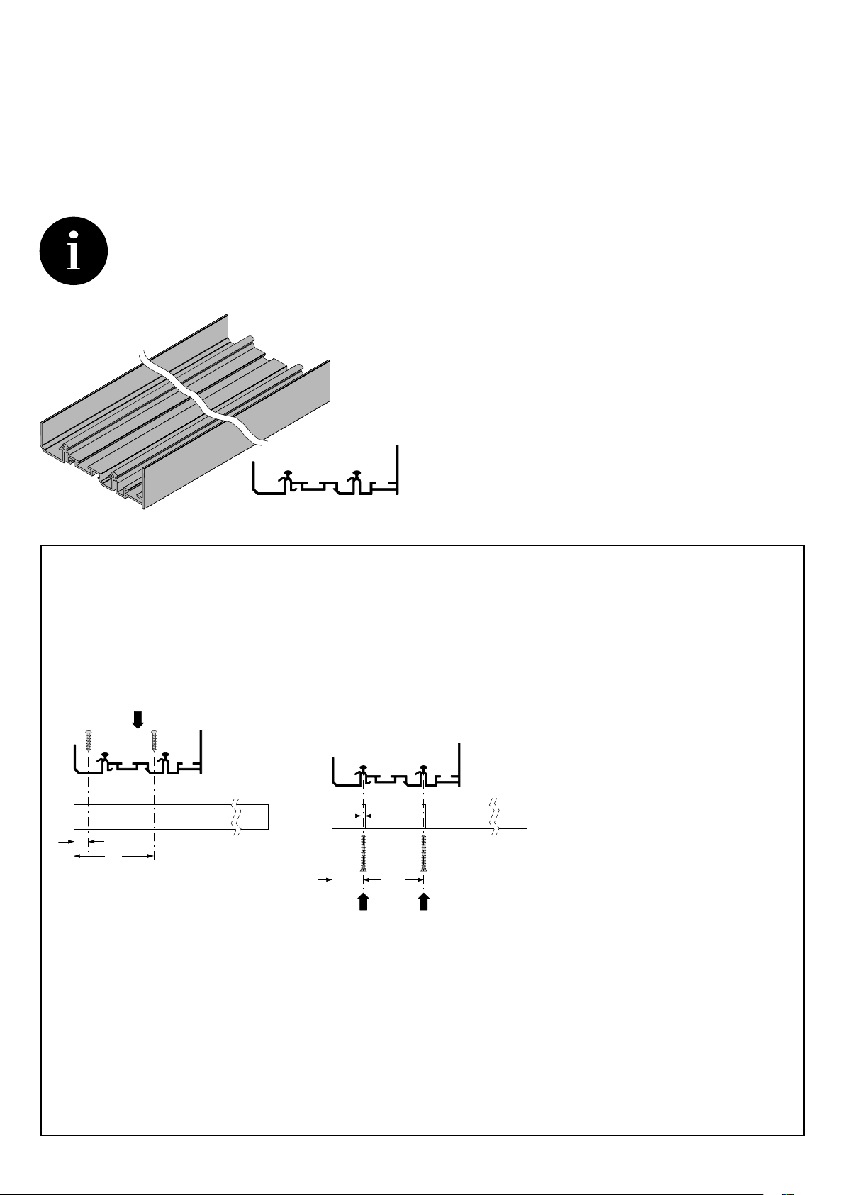
Tutte le misure espresse in questo opuscolo
sono in millimetri.
ATTENZIONE
Non utilizzare spray ed oli anti frizione o
sblocca filetti sui cuscinetti o sulle ruote con
O-ring dei pattini scorrevoli. Questo pro-
voca lo scioglimento dei grassi dei cusci-
netti rendendoli rumorosi oppure la rottura
dell’O-ring.
ABBREVIAZIONI
W larghezza
WA larghezza anta
L lunghezza
LB lunghezza binario
D profondità
H altezza
I interasse
T spessore
S sormonto
Le illustrazioni e le descrizioni di questo
opuscolo si intendono fornite a titolo indica-
tivo. L’azienda si riserva pertanto di appor-
tare, in qualsiasi momento e senza preav-
viso, quelle modifiche che ritenesse utili per
qualsiasi esigenza di carattere costruttivo e
commerciale.
Alle Maße in diesem Katalog sind in Milli-
metern.
ACHTUNG
Kein Spray, Schmiermittel oder Lösen-mittel
auf die Kugellager und Rollen mit O-Ring
der Laufwagen verwenden. Das kann die
Kugellager und die Rollen geräuschvoller
machen und kann den O-Ring Abriss verur-
sachen.
ABKÜRZUNGS
W Breite
WA Türbreite
L Länge
LB Länge Schienen
D Tiefe
H Höhe
I Abstand zwischen den Zentren
T Dicke
S Überlappung
Die Bilder und Beschreibungen dieses Pro-
spektes sind nur zur Information gegeben.
Die Firma kann, in jedem Moment, Änd-
erungen und Verbesserungen ohne Voran-
kündigung vornehmen.
All dimensions in this leaflet are stated in
millimeters.
WARNING
Do not use any anti-friction oil or grease or
thread-realese spray on ball bearing or on
wheels with O-ring, it can cause the mel-
ting of the inside ball bearing grease, ma-
king them noisy or causing the break of the
O-ring of the wheels.
ABBREVIATIONS
W width
WA door width
L length
LB rail length
D depth
H height
I distance between centres
T thickness
S overlapping
The pictures and descriptions this leaflet con-
tains are supplied for information purposes.
The company reserves the right to introduce
those modifications it deems opportune for
any construction or commercial need at any
time and without advance notice.
Todas las dimensiones en este folleto se
expresan en milímetros.
ADVERTENCIA
No utilices spray y aceites anti-fricción so-
bre los cojinetes de bolas y sobre las ruedas
con O-ring de los patines. Esto puede pro-
vocar mayor rumorosidat de los cojines o la
rotura de los O-ring.
ABREVIACIONES
W anchura
WA anchura de la puerta
L longitud
LB longitud de la guía
D profundidad
H altura
I distancia entre centros
T espesor
S superposición
Las imagines y las descripciones de este
folleto solo se fechas a titulo informativo.
La empresa puede aportar, en cualquier
momento y sin preaviso, las modificaciones
que cree necesarias por exigencias técnicas
y comerciales.
Toutes les mesures indiquées dans cette bro-
chure sont en millimètres.
AVERTISSEMENT
Ne pas utiliser de spray ni d’huile anti frot-
tement ou pour débloquer les filets sur les
coussinets ou sur les roulettes avec bague
torique des patins coulissants. Ce qui ferait
fondre la graisse des roulements en les ren-
dant bruyants ou provoquerait la rupture de
la bague torique.
ABRÉVIATIONS
W largeur
WA largeur de la porte
L longueur
LB longueur de le rail
D profondeur
H hauteur
I entraxe
T épaisseur
S chevauchement
Les images et les descriptions de cette notice
ne sont fournies qu’à titre indicatif. Le fabri-
cant se réserve donc le droit d’apporter tou-
tes les modifications qu’il jugera utiles à des
fins techniques et commerciales à n’importe
quel moment et sans aucun préavis.
2

Cabinet Requirements
Top Height Clearance = Min 60mm
Bottom Height Clearance = Min 60mm
Bottom Depth Clearance = Min 75mm

3
Lavorazioni richieste per le ante
Working requests for the doors
Usinage nécessaire pour les portes
Verarbeitungsanforderungen für die Türen
Laboreo necesario para las puertas
25
17
4
Ø7,5x11
(-0 +0,5)
25
25 10
7
Ø7,5x11
(-0 +0,5)
option
2
H 17
option
1
H 25
H 35
1
2
Working requests for the doors
3
Lavorazioni richieste per le ante
Working requests for the doors
Usinage nécessaire pour les portes
Verarbeitungsanforderungen für die Türen
Laboreo necesario para las puertas
25
17
4
Ø7,5x11
(-0 +0,5)
25
25 10
7
Ø7,5x11
(-0 +0,5)
option
2
H 17
option
1
H 25
H 35
1
2
2 x locating holes
7.5mm wide x 11mm deep

Istruzioni di montaggio
Assembly instructions
Instructions de montage
Montageanleitungen
Instrucciones de ensamblaje
31
45
3,5
Click Click
Fissare il binario
superiore al
mobile secondo la
modalità scelta:
1a, 1b, 1c, 1d.
Fix the upper rail
to the wardrobe
according to your
choice: 1a, 1b, 1c,
1d.
Fixer le rail supérieur
au meuble selon le
mode choise: 1a, 1b,
1c, 1d.
Befestigen Sie die
obere Schiene an den
Schrank nach der
gewählten Methode:
1a, 1b, 1c, 1d.
Fijar la guía superior
al mueble según
vuestra elección: 1a,
1b, 1c, 1d.
1d
10,5
54
21,5 41,5
Ø4
31
45
1a 1b 1c
Scegliere il tipo di binario superiore / Choose the type of upper rail /
Choisissez le type de rail supérieur / Wählen Sie den Typ der oberen Schiene /
Elija el tipo de guía superior
4
Assembly instructions
Fix the upper rail to the wardrobe according to your choice: 1a or 1b
Screw Position 10.5mm and
54mm in from carcase edge
on under side of carcase
Screw Position 21.5mm and 63mm
in from carcase edge on inside of carcase
Choose the type of upper rail

5
Click
45
MIN 67
15
10,5
MIN 42
45
33,5
3,5
10
15
MIN 67
33,5
MIN 42
Ø4
2
3a
3d
3b
3c
Fissare il binario
inferiore al
mobile secondo la
modalità scelta:
3a, 3b, 3c, 3d.
Fix the lower rail
to the wardrobe
according to your
choice: 3a, 3b, 3c,
3d.
Fixer le rail inférieur
au meuble selon le
mode choise: 3a, 3b,
3c, 3d.
Befestigen Sie die
untere Schiene an
den Schrank nach der
gewählten Methode:
3a, 3b, 3c, 3d.
Fijar la guía inferior al
mueble según vuestra
elección: 3a, 3b, 3c,
3d.
Fix the lower rail to the wardrobe according to your choice: 3a or 3b
Screw Position 10.5mm in from
carcase edge on under side of carcase
Screw Position 33.5mm in from
carcase edge on inside of carcase

6
46 46
46
400 mm MIN
46 46
46
46
46
46
46
Schemi posizionamento fermi superiori
Positioning of the upper locks
Positionnement des butées supérieurs
Positionierung der obere Aufschläge
Posicionamiento de los topes superiores
No Softspace
A
B
C
Positioning of the upper locks
Min 400mm door for standard opening/closing

90°90°
optional
Schema posizionamento fermo superiore centrale
Positioning of the upper central lock
Positionnement de la butée centrale supérieure
Positionierung der oberen Mittelsperre
Posicionamiento del tope central superior
90°90°
4 mm
4a
Sistema di fissaggio dall’alto.
Locking system from the top.
Système de fixation par le haut.
Befestigungssystem von der Spitze.
Sistema de fijación desde la parte superior.
7
Positioning of the upper central lock
Locking system from the top

8
2
1
5a
4 mm

9
2
6a
4 mm
1

10
400 mm MIN
L R R
400 mm MIN
L L R
400 mm MIN
RL
400 mm MIN
L R
A
B
C
Schemi posizionamento ammortizzatori e attivatori.
Positioning of soft-closing device and activators.
Schémas de positionnement système amortissement et activateurs
Schemen zur Positionierung des Dämpfungssystems und der Aktivatoren.
Esquemas de colocación del sistema de amortización y activadores.
Positioning of soft-closing device and activators

90°90°
R
optional
Schema posizionamento fermo superiore centrale
Positioning of the upper central lock
Schémas de positionnement de la butée centrale supérieure
Schemen zur Positionierung der oberen Mittelsperre
Esquemas de colocación del tope central superior
11
Positioning of the upper central lock

12
760 mm MIN
L R R
760 mm MIN
L L R
400 mm MIN
RL
400 mm MIN
RL
A
B
C
Schemi posizionamento ammortizzatori e attivatori.
Positioning of soft-closing device and activators.
Schémas de positionnement système amortissement et activateurs
Schemen zur Positionierung des Dämpfungssystems und der Aktivatoren.
Esquemas de colocación del sistema de amortización y activadores.
Positioning of soft-closing device and activators
Min 760mm door for 2 Door Easyline opening/closing

13
90°90°
4b
4 mm
Sistema di fissaggio dall’alto.
Locking system from the top.
Système de fixation par le haut.
Befestigungssystem von der Spitze.
Sistema de fijación desde la parte superior.
optional
Schema posizionamento ammortizzatore centrale e attivatore
Positioning of central soft-closing device and activator
Schémas de positionnement système amortissement centrale et activateur
Schemen zur mittleren Positionierung des Dämpfungssystems und der Aktivatoren
Esquemas de colocación del sistema de amortización central y activadores
Positioning of central soft-closing device and activators
Locking system from the top
Attachment for outer door,
opening both ways

90°90°
14

15
3
12
5b
4 mm

16
3
6b
4 mm
1
2

17
78
option
5 mm
DISTANZIATORE PER ANTE
DOORS SPACER
ENTRETOISE POUR PORTES
SPACER FÜR TÜREN
ESPACIADOR PARA PUERTAS
22 - 43
22 mm
43 mm
DOOR SPACER

18
PARACOLPI PER SOLA ANTA INTERNA SX - UTILIZZO CON ARMADIO A 3 ANTE
BUMPERS ONLY FOR LEFT INTERNAL DOOR - USABLE WITH 3 DOORS WARDROBE
BUTOIR POUR UNE PORTE INTÉRIEUR GAUCHE - À UTILISER AVEC ARMOIRE 3 PORTES
ANSCHLAG NUR FÜR DIE LINKE TÜR - VERWENDET NUR FÜR DIE DREITURIGEN SCHRANK
PARAGOLPE PARA LA PUERTA INTERNA – USO EN ARMARIOS DE 3 PUERTAS
9
BUMPERS ONLY FOR LEFT INTERNAL DOOR - USABLE WITH 3 DOORS WARDROBE

19
OK
NO
NO
Anta regolata troppo in alto.
Door adjusted too high.
Porte réglé trop haut.
Tür zu hoch eingestellt.
Puerta demasiado alto.
Anta regolata troppo in basso.
Door adjusted too low.
Porte réglé trop bas.
Tür zu niedrig eingestellt.
Puerta demasiado bajo.
10
Other manuals for CINETTO VOLO
1
This manual suits for next models
1
Table of contents