© by WilTec Wildanger Technik GmbH Seite 9
http://www.wiltec.info
Wood Stud Installation
For secure wood stud mounting, the wall plate must be mounted to two studs at least
16” apart.
1. Use a high-quality electronic stud finder (commercially available) to locate two
adjacent studs and mark their locations with a pencil.
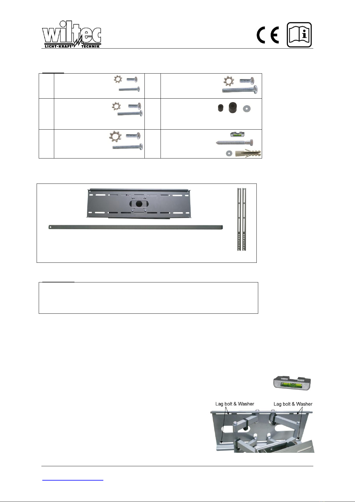
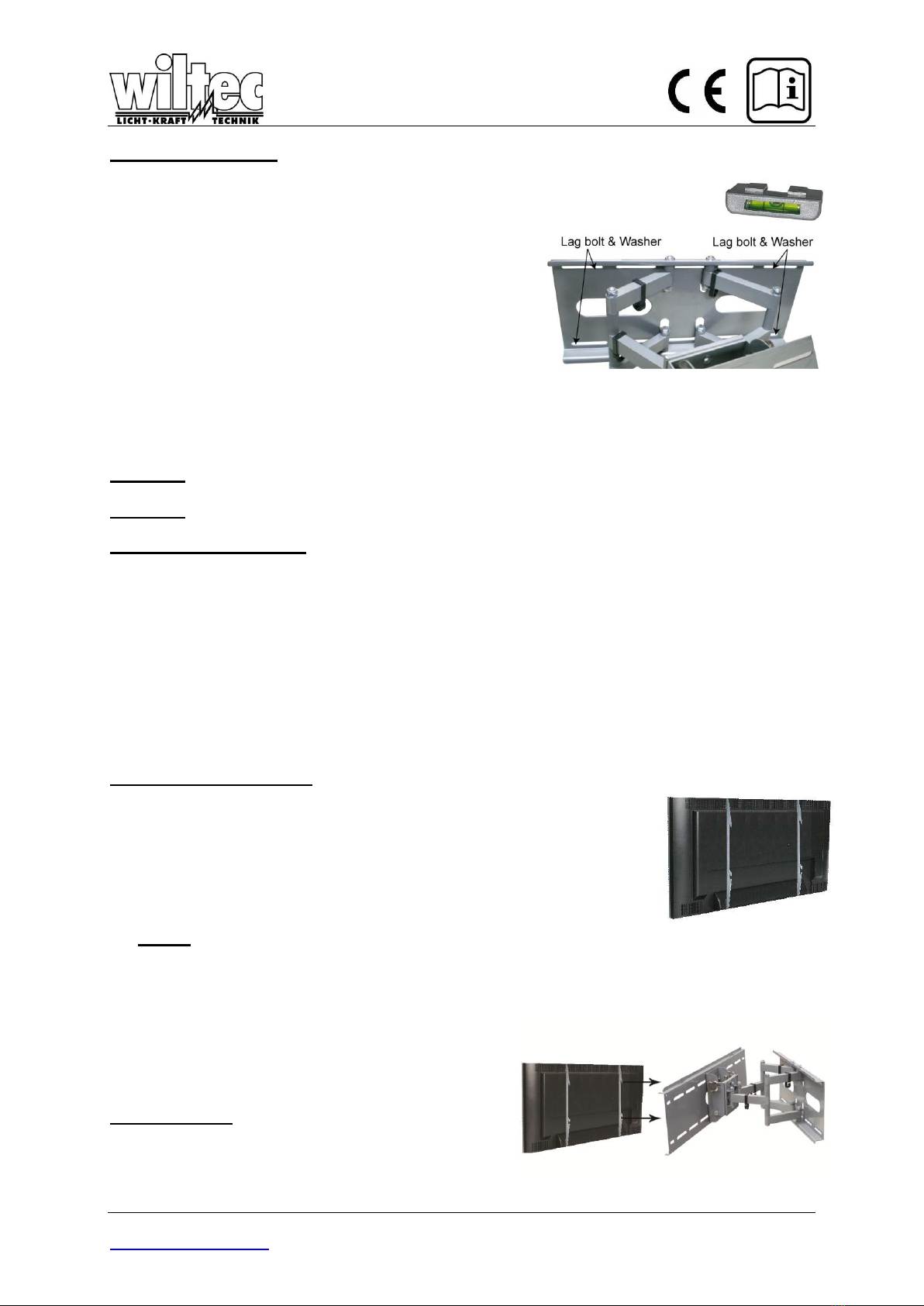
2. With the help of an assistant, and using the bubble level
to ensure the wall plate is level, position the wall plate
against the wall in the desired mounting location.
3. Mark the right, upper and lower and the left (upper and
lower), positions of the small horizontal slots that are in
alignment with the studs.
4. You should mark four positions total.
5. Next, pre-drill a 3mm hole in the wall stud at each
marked location.
6. With the help of an assistant, position the wall plate against the wall and line up the mounting slots
with drilled holes.
7. For each location, insert a lag bolt and washer into the wall.
8. Tighten bolt with an open ended socket wrench by turning clockwise until tight.
CAUTION: Do not over-tighten bolts-doing so may cause unnecessary damage to the wall. Avoid
excessive torque.
CAUTION: Do not release the wall plate until it is properly mounted and secured to the wall.
Concrete/Brick Installation
NOTE: The concrete anchors must be used for concrete installation. They can be purchased at
your local hardware store.
1. Begin by placing the wall plate into position against the wall, using the bubble level to keep it level.
2. Mark off four holes to be used for securing the mount and place the wall plate aside.
3. Next, drill holes using an electric drill and 10mm masonry bit.
4. Insert a concrete anchor into each hole.
5. If necessary, a hammer can be used to lightly tap each anchor into place so that they are flush
with the wall.
6. Once all of the anchors are in place, move the wall plate back into position.
7. Attach the screw into the anchor that is placed in the wall.
8. Do not tighten until all screws are in place.
Display Bracket Installation
1. To ensure optimal installation, this kit includes various screws of different
diameters and lengths.
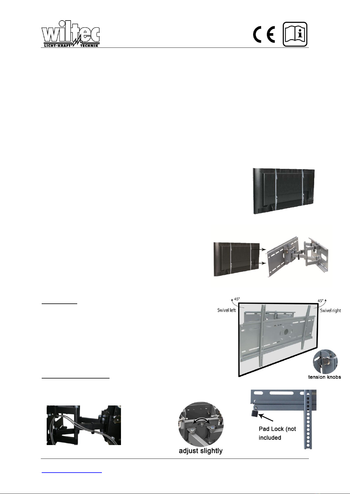
2. Place your TV screen down on a soft, flat surface, and locate the
threaded mounting points that are located on the back of the display.
3. Determine which screw is the correct length by carefully inserting a
straw, or toothpick, and mark how deep the mounting point is.
4. If your display has a curved back or a recessed thread mounting point, a
spacer must be used.
NOTE: Select the spacer that is closest in depth to the recess to keep
your bracket as close to the display as possible.
5. Place the spacer between the mounting bracket and the display.
6. If a smaller screw is being used(M4,M5 or M6),
please use a washer with each screw for added
stability.
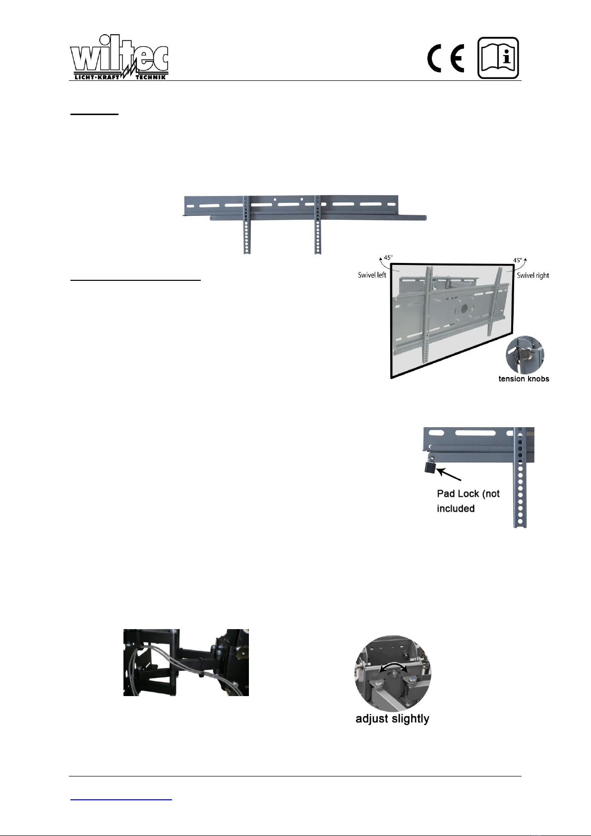
Final Installation
Attach each bracket to the display by aligning the holes
on each bracket, with the threaded inserts on the back
panel of your display, inserting the screws through both
and turning clockwise until they are fully inserted.