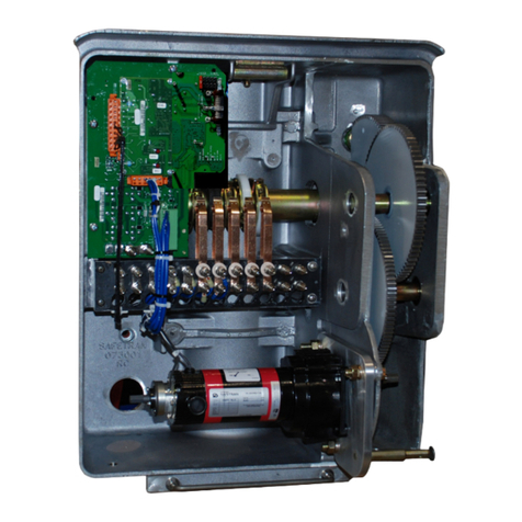
Siemens 545-714 User manual
Other Siemens Control Unit manuals
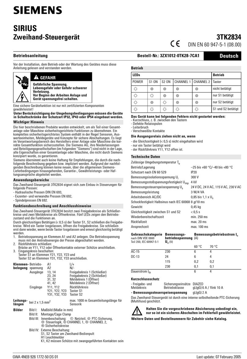
Siemens
Siemens SIRIUS 3TK2834 User manual
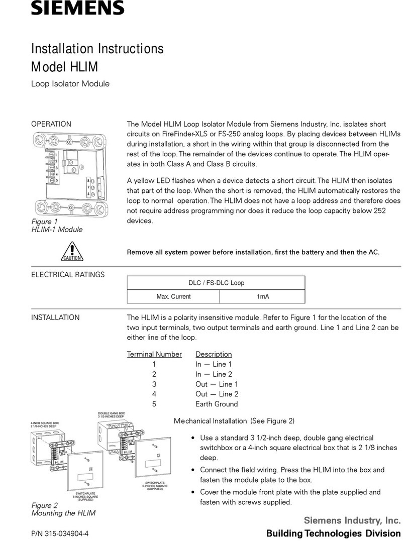
Siemens
Siemens HLIM Service manual
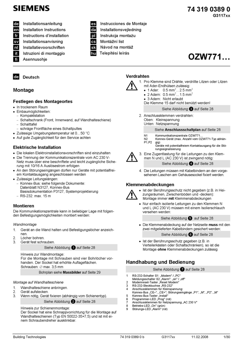
Siemens
Siemens OZW771 User manual
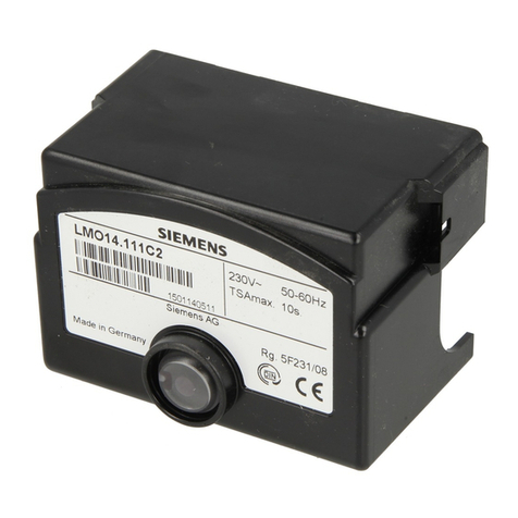
Siemens
Siemens LMO14 Series User manual
Siemens
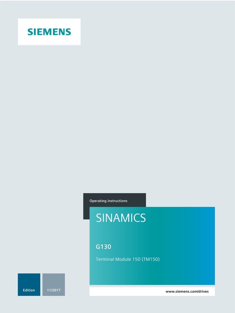
Siemens SINAMICS G130 TM150 User manual
Siemens
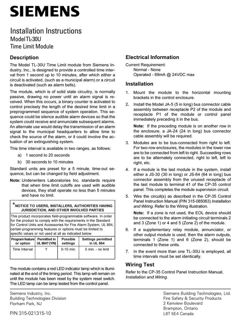
Siemens TL-30U User manual
Siemens
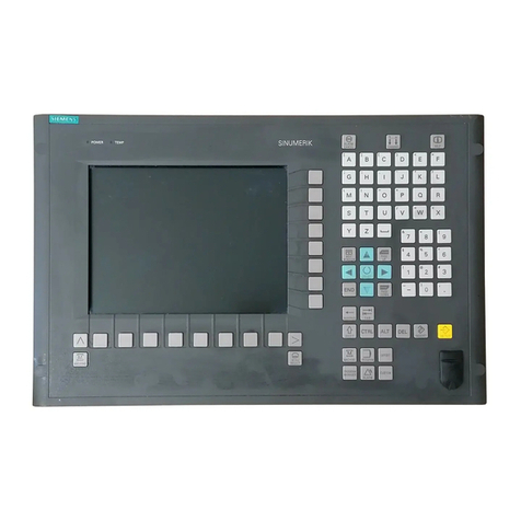
Siemens SINUMERIK 810D Quick start guide

Siemens
Siemens SIMATIC ET 200SP User manual
Siemens
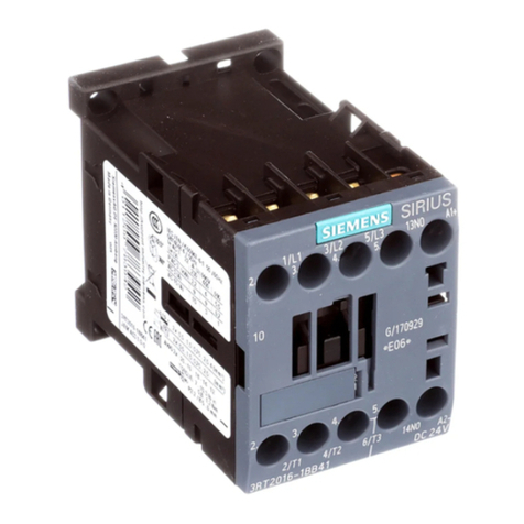
Siemens SIRIUS 3RT1916-4KA User manual
Siemens
Siemens 6AV7861 Series User manual
Siemens
Siemens QAW910 User manual
Siemens
Siemens SIMATIC ET 200eco PN Technical Document
Siemens
Siemens FC1008-A Manual
Siemens
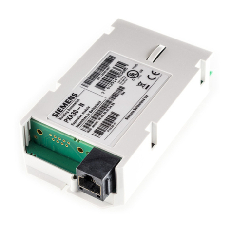
Siemens PXA30 Series User manual
Siemens
Siemens SIMATIC FM 351 User manual
Siemens
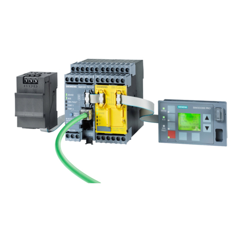
Siemens SIMOCODE pro User manual
Siemens
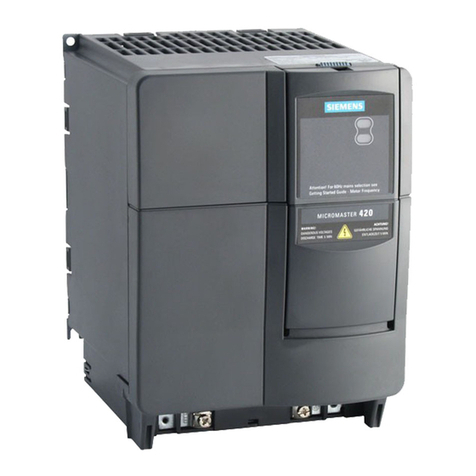
Siemens MICROMASTER 420 User manual
Siemens
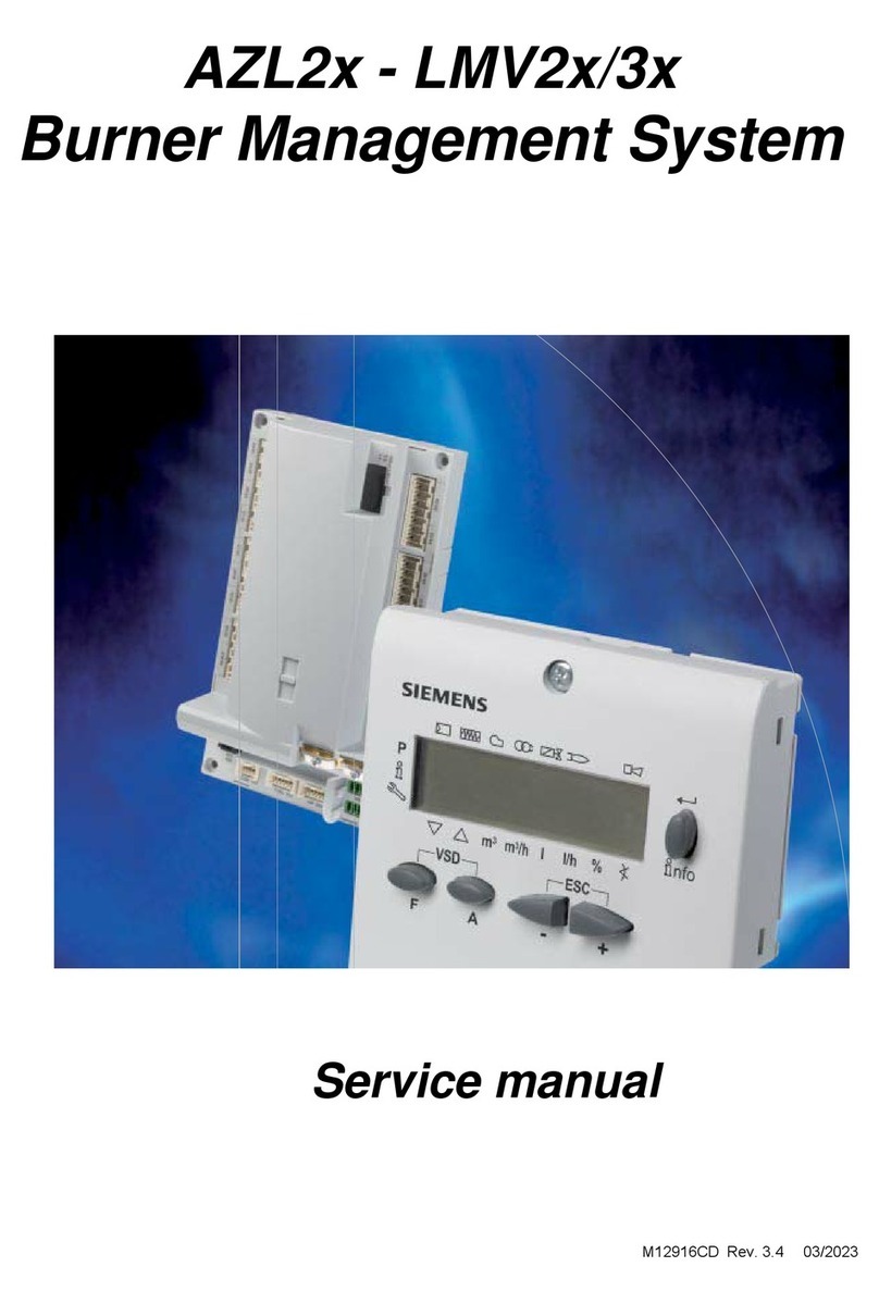
Siemens AZL2 Series User manual
Siemens
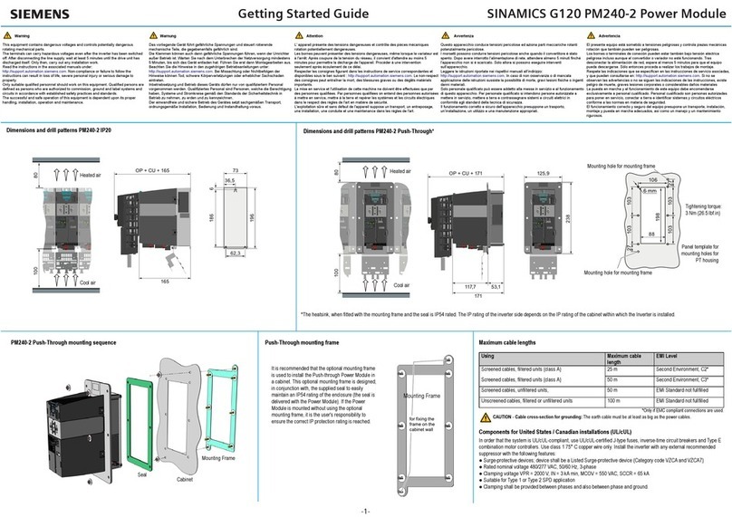
Siemens SINAMICS G120 PM240-2 User manual
Siemens
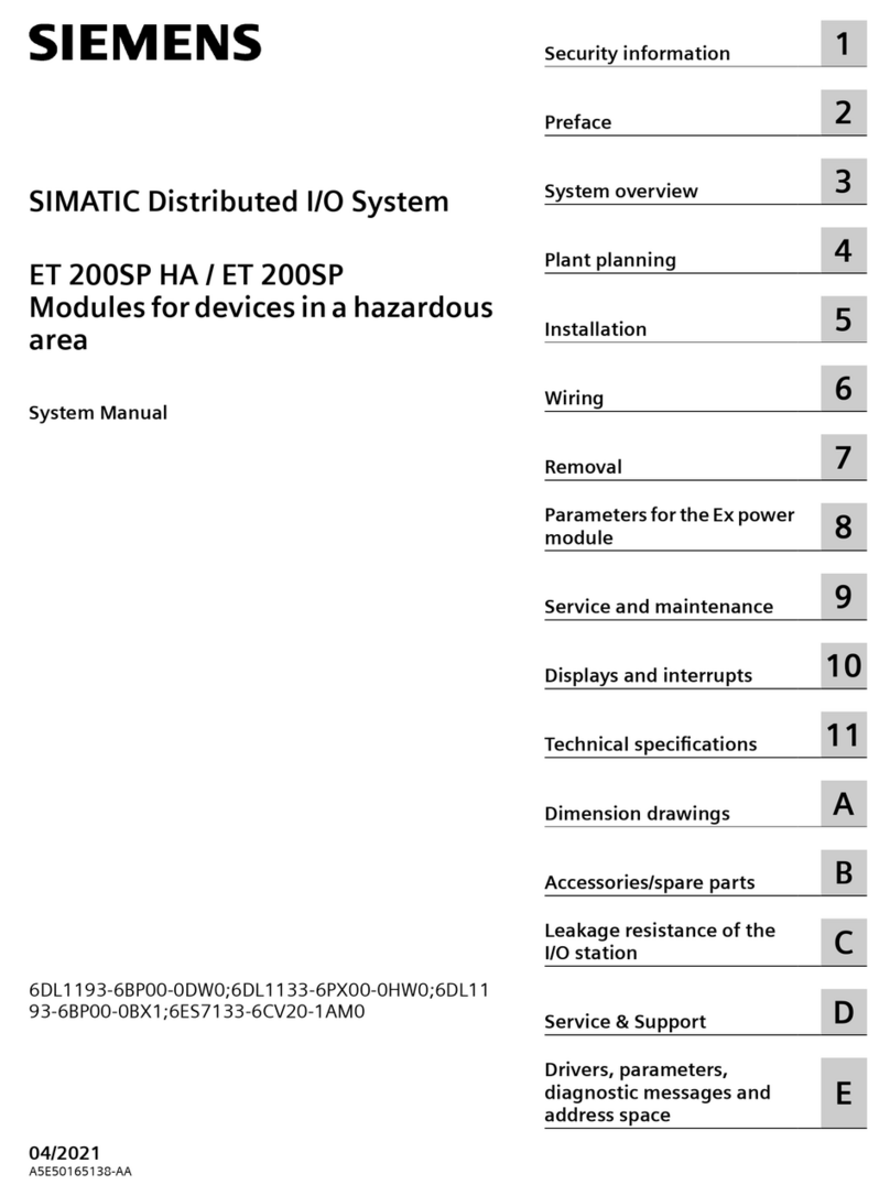
Siemens SIMATIC ET 200SP HA User guide
Popular Control Unit manuals by other brands

Festo
Festo Compact Performance CP-FB6-E Brief description

Elo TouchSystems
Elo TouchSystems DMS-SA19P-EXTME Quick installation guide

JS Automation
JS Automation MPC3034A user manual

JAUDT
JAUDT SW GII 6406 Series Translation of the original operating instructions

Spektrum
Spektrum Air Module System manual

BOC Edwards
BOC Edwards Q Series instruction manual

KHADAS
KHADAS BT Magic quick start

Etherma
Etherma eNEXHO-IL Assembly and operating instructions

PMFoundations
PMFoundations Attenuverter Assembly guide

GEA
GEA VARIVENT Operating instruction

Walther Systemtechnik
Walther Systemtechnik VMS-05 Assembly instructions

Altronix
Altronix LINQ8PD Installation and programming manual
