OWNERS OPERATING & MAINTENANCE MANUAL
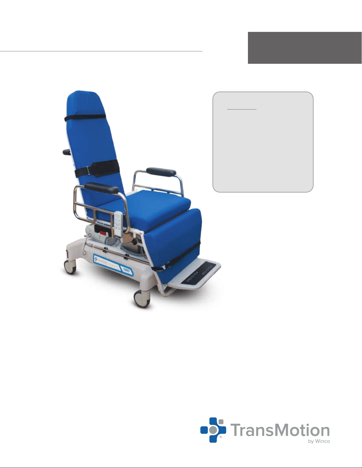
TMM3 VIDEO FLUOROSCOPY STRETCHER-CHAIR
Page 3 of 28
Document #OM-TMM-2228-13
Revision: V
TABLE OF CONTENTS
S W / S ..................................................................................................................
I U S ..................................................................................................................
T, S, H & D .....................................................................
P: B .....................................................................................................
P / C R..........................................................................................................
S P...........................................................................................................................
W .....................................................................................................................................................................
A W .............................................................................................................................................
C ......................................................................................................................................................................
EMI C..............................................................................................................................................................
N .........................................................................................................................................................................
P L / D.............................................................................................................
O.........................................................................................................................................................................
O I ...................................................................................................................
Q R B S...............................................................................................................................
C B O ......................................................................................................................................
S R O.................................................................................................................................................
A S R A...................................................................................................................................
P (C) ...........................................................................................................................................
P I / E .......................................................................................................................................
P T ......................................................................................................................................................
P B O ...............................................................................................................................................
S R ............................................................................................................................................................
O..................................................................................................................................................
“S” O: S B..........................................................................................................................................
“F” O: M F F ..........................................................................................................
“E” O: E...................................................................................................................................................
“B” O: B P ......................................................................................................................................
“A” O: AC P ( - )............................................................
S S...............................................................................................................................
C I ......................................................................................................................
P S C .......................................................................................................................................
R TMM P / P S F S-C .........................................................................
P M..............................................................................................................
B S I...........................................................................................................
W I.....................................................................................................................
L W.....................................................................................................................................................
O E L W...........................................................................................................
S C I ...............................................................................................