2
Contents
1Safety information....................................................................................................................................................... 4
1.1 Safety ................................................................................................................................................................4
1.2 230V AC............................................................................................................................................................4
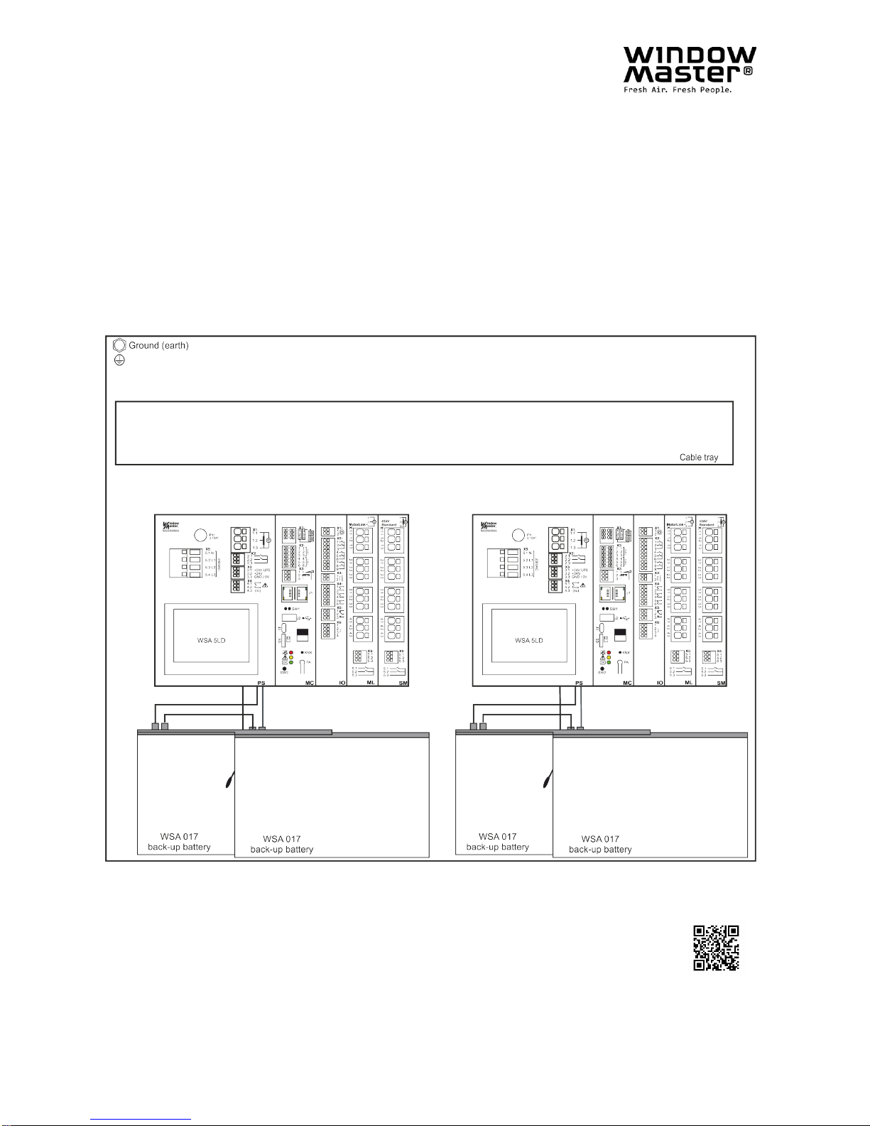
1.3 Back-up batteries...............................................................................................................................................4
1.4 Application.........................................................................................................................................................4
1.5 Cable routing and electrical connection.............................................................................................................4
2Structure of the smoke panel..................................................................................................................................... 5
3Variants of panels........................................................................................................................................................ 7
3.1 Number of motor lines, inputs and outputs depending on the combination of the three expansion modules ....8
3.2 Examples with FlexiSmoke™ ............................................................................................................................8
3.3
Max numbers of motors per motor line which can be connected per module
.......................................................... 9
4Modules, accessories, spare parts.......................................................................................................................... 10
5Technical data ........................................................................................................................................................... 11
6Mounting.................................................................................................................................................................... 13
7Installation ................................................................................................................................................................. 13
7.1 Cable routing...................................................................................................................................................13
7.2 Cables into housing.........................................................................................................................................13
7.3 Connection of safety earth wire and 230V AC................................................................................................. 14
7.4Installation of the break glass unit, ventilation keypad and smoke detector..................................................... 14
7.5 Assembly instructions...................................................................................................................................... 14
8Cable dimensioning .................................................................................................................................................. 14
8.1 Maintaining the cable functions .......................................................................................................................14
8.2 Formula for the calculation of the maximum motor cable length......................................................................14
8.3 Max. cable Length ........................................................................................................................................... 15
8.3.1 Max cable length –±24V standard motors ................................................................................................. 15
8.3.2 Max cable length –motors with MotorLink®................................................................................................ 16
8.3.3 Max cable length –Pyrotechnic gas generator........................................................................................... 16
9Cable plan for connection to WSC 520 / WSC 540 / WSC 560............................................................................... 17
10 Description of modules............................................................................................................................................. 18
10.1 WSA 5PS power supply module 20A ..............................................................................................................18
10.2 WSA 5MC overall control module....................................................................................................................20
10.3 WSA 5IO input/output module......................................................................................................................... 25
10.4 WSA 5SM standard motor module ..................................................................................................................27
10.5 WSA 5ML MotorLink®motor module...............................................................................................................29
11 Cable monitoring of motors ..................................................................................................................................... 30
11.1 Usage of non-WindowMaster motors .............................................................................................................. 31
12 Back-up batteries ...................................................................................................................................................... 31
13 Touch screen............................................................................................................................................................. 31
13.1 Icons................................................................................................................................................................ 32
13.2 Rotation of the touch screen............................................................................................................................32
14 Configuration –main menu...................................................................................................................................... 32
14.1 Motor lines –motor groups –smoke zones.....................................................................................................33
14.1.1 Examples with motor lines / motor groups / smoke zones.......................................................................... 33
14.2 Motor line.........................................................................................................................................................34
14.2.1 Motor line - numbering................................................................................................................................ 34
14.2.2 Motor line - configuration............................................................................................................................ 34
14.2.3 Colour code - motor line............................................................................................................................. 35
14.3 Motor group..................................................................................................................................................... 35
14.3.1 Motor group - configuration......................................................................................................................... 36
14.3.2 Colour code –motor group......................................................................................................................... 36
14.4 Break glass unit............................................................................................................................................... 36
14.4.1 Break glass unit –configuration.................................................................................................................. 36
14.4.2 Colour code –break glass unit................................................................................................................... 37
14.5 Smoke zone..................................................................................................................................................... 37
14.6 Local input.......................................................................................................................................................39
14.6.1 Numbering of local inputs........................................................................................................................... 39
14.6.2 Local input - configuration........................................................................................................................... 39
14.6.3 Usage of wind/rain sensors - WLA 33x....................................................................................................... 40
14.7 Local output.....................................................................................................................................................41
14.7.1 Numbering of local output........................................................................................................................... 41
14.7.2 Local output - configuration ........................................................................................................................ 42
14.8 Weather station type........................................................................................................................................ 43
14.9 Sequence control............................................................................................................................................. 43
14.10 Magnetic clamp (magnetic door retainer) ........................................................................................................45
14.11 Pyrotechnic gas generator............................................................................................................................... 46
14.12 Alarm output.................................................................................................................................................... 46
14.13 CAN bus.......................................................................................................................................................... 47
14.14 Network ...........................................................................................................................................................48
14.15 Fieldbus...........................................................................................................................................................49
14.15.1 KNX-bus..................................................................................................................................................... 49
14.15.2 BACnet....................................................................................................................................................... 49