Wine Corner SP40CAPRO Operation manual

INSTALLATION & USER GUIDE
DEFYING
CONVENTION
Wine Cellar Conditioning Unit
SP40CAPRO for Bespoke Wine Cabinets

INSTALLATION AND USER MANUAL WINESP40CAPRO
Page 3
User manual
Table of contents
1.TECHNICAL DATAS ....................................................................................5
2.EQUIPMENT...............................................................................................7
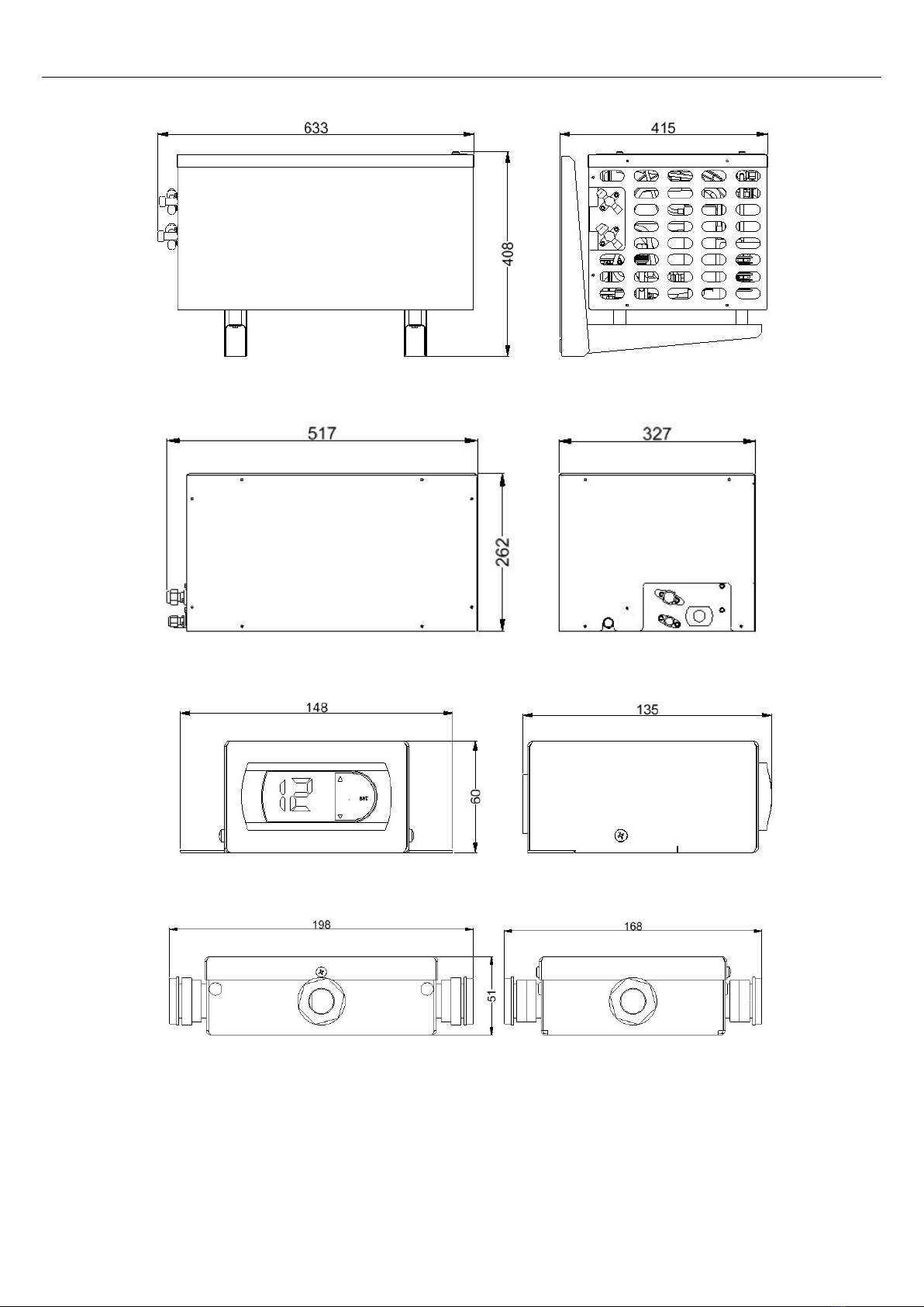
2.1.Outside unit .............................................................................................. 7
2.2.Inside unit ................................................................................................ 7
2.3.Thermostat ............................................................................................... 7
2.4.Connection box ......................................................................................... 7
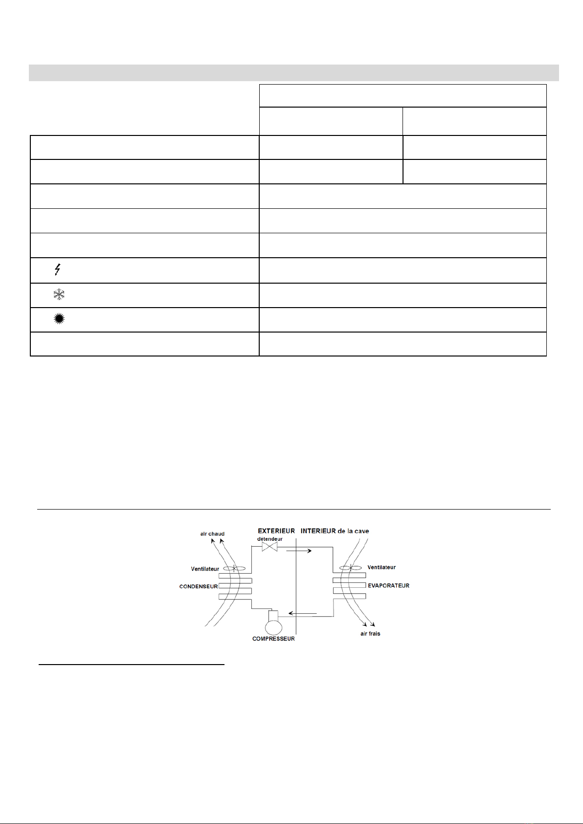
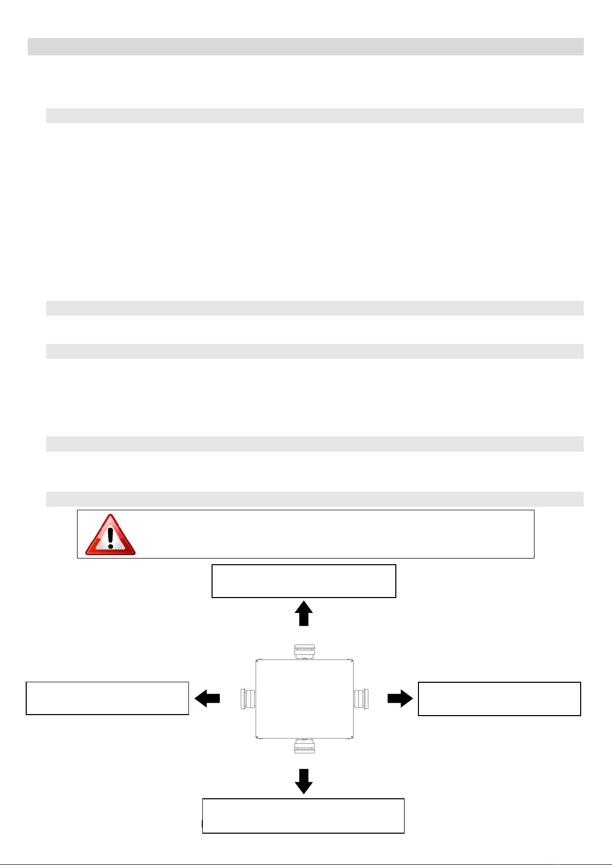
2.5.Connection drawing ................................................................................... 7
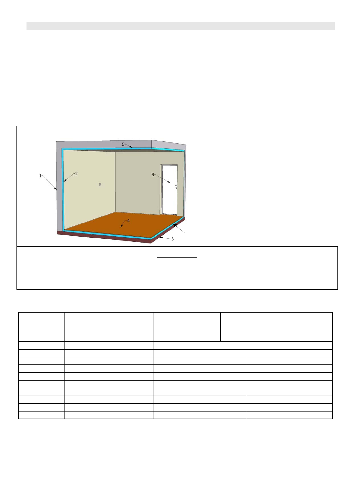
2.6.Cellar insulation......................................................................................... 8
2.6.1.Insulation of walls, ceiling and floor ................................................................................9
2.6.2.The door ......................................................................................................................9
2.6.3.Insulation of other elements...........................................................................................9
3.INSTALLATION OF THE AIR CONDITIONER WINEMASTER®.....................10
3.1.List of required material ..............................................................................10
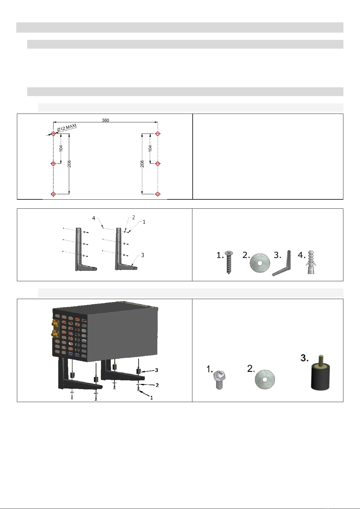
3.2.Installation of the outside unit .....................................................................10
3.2.1.Brackets installation ....................................................................................................10
3.2.2.Fixing the outside unit .................................................................................................10
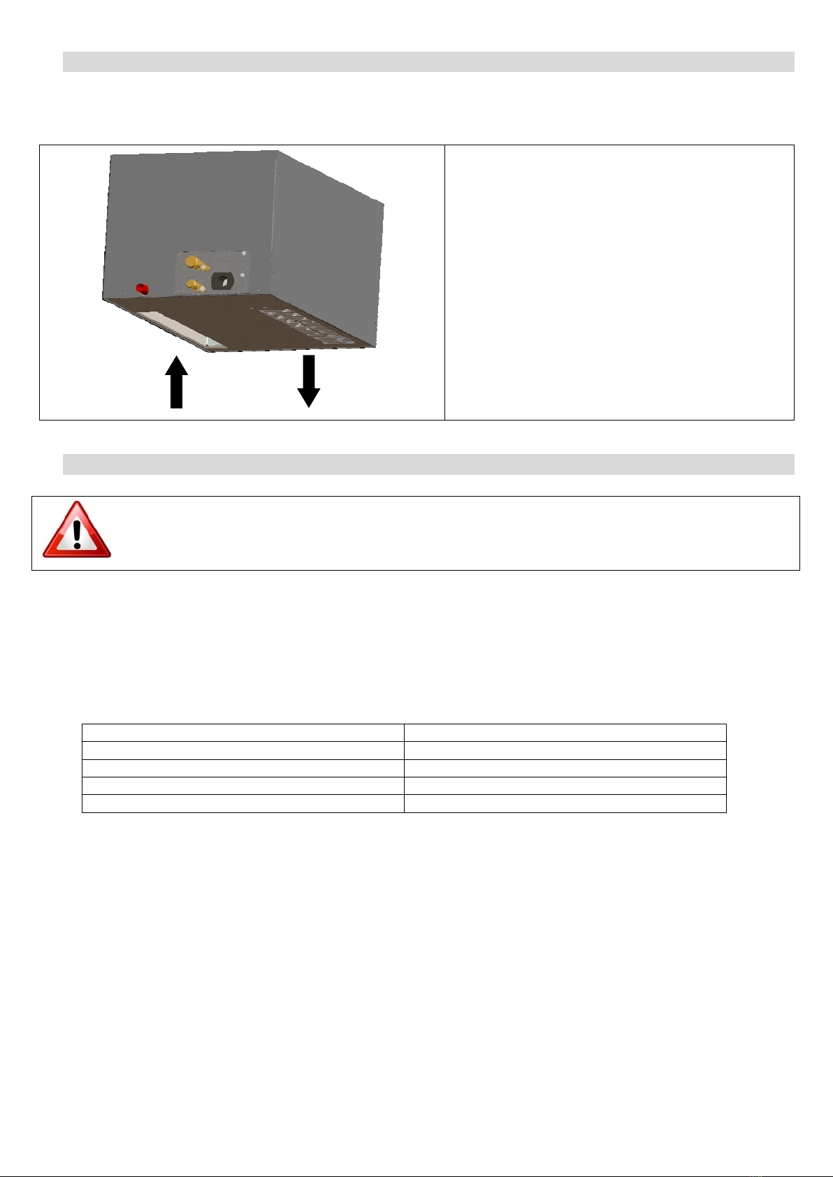
3.3.Installation of the inside unit .......................................................................11
3.4.Ducting connection .....................................................................................11
3.5.Electric connection .....................................................................................12
3.5.1.Connection of outside unit............................................................................................12
3.5.2.Connection of inside unit..............................................................................................12
3.5.3.Plugging.....................................................................................................................12
3.5.4.Wiring drawing ...........................................................................................................13
3.6.Installation of the water drain system ...........................................................14
4.PLUGGING THE AIR CONDITIONER WINEMASTER®.................................14
4.1.Connecting the air conditioner .....................................................................14
4.2.Start up ....................................................................................................15
4.2.1.Temperature setting ....................................................................................................15
4.2.2.Standby mode ............................................................................................................15
4.2.3.Automatic defrost........................................................................................................15
5.MAINTENANCE OF THE AIR CONDITIONER WINEMASTER®.....................16
5.1.Filter and outside unit cleaning ....................................................................16
5.2.Condensates drain......................................................................................16
6.WARRANTY..............................................................................................17
6.1.Legal warranty...........................................................................................17
6.2.2 years contractual warranty .......................................................................17
6.3.Warranty conditions....................................................................................17
6.4.Exclusions and limitations of warranty ..........................................................17
GB

INSTALLATION AND USER MANUAL WINESP40CAPRO
Page 4
Introduction
You purchased an air conditioner WINEMASTER®and we thank you for your confidence.
From conception to marketing, everything
has been implemented to offer an
exclusive and high quality product. Brainchild of a team who find in this a motivation to
ever satisfy you, we hope that your wine conditioning unit WINEMASTER®will bring you
great storage conditions and best wines aging for an incomparable pleasure.
Because the customer is at the heart of all our thoughts, we want to support you in your
first steps and lead you towards the best use of your air conditioner every day. Thus,
you will find in this manual technical information and practical advice to help you to deal
with the essential steps to installation and use.
In order that your wine tasting remains moments to share, FONDIS guarantees you a
sincere engagement, dedicated expertise and ongoing follow-up at your service!
FONDIS.

INSTALLATION AND USER MANUAL WINESP40CAPRO
Page 5
1. TECHNICAL DATAS
WINESP40CAPRO
Outside unit Inside unit
Weight of units 35 kg 17 kg
Dimensions H x L x D 408 x 633 x 415 262 x 517 x 327
Temperature setting Preset at 12°C, adjustable between 4 & 15°C *
Maximum outside temperature. 40°C **
Cooling power 900 W at 15°C **
Electricity supply 230/240V-50 Hz
Electric power 600 W
Heating power 500 W
Gas R404A
The circuit breaker must be at least 16 Amps.
*The insulation has to be in accordance with the volume of the cellar and the set temperature.
** The cooling performance is dependant from the outside temperature. Therefore, the set temperature
of 12°C for the cellar cannot be maintained if the outside temperature reaches the 40°C.
If the thermal safety functions to often, there is a risk for the compressor to be damaged. In all cases, it
must be avoid that the outside temperature remains at 40°C, this high temperature should be limited
to the summer period.
VENTILATED COLD OR « NO FROST » ( schematic diagram)
The advantages of « ventilated cold »:
-No frost other than on the evaporator.
-Automatic defrosting and maximized refrigeration efficiency.
-Cold distribution improved by a permanent air circulation (without air stratification).
The circulation of air allows maintaining the pre-selected temperature throughout the cellar

INSTALLATION AND USER MANUAL WINESP40CAPRO
Page 6
Technical drawing
Outside unit
Inside unit
Thermostat
Wiring box

INSTALLATION AND USER MANUAL WINESP40CAPRO
Page 7
2. EQUIPMENT
The air conditioner is composed of 2 separate units, of a thermostat and a wiring box. They must be
connected by frigorific ducting pipes and electric connections.
The ducting pipes length between both units should not exceed 20m.
2.1. Outside unit
The unit must be installed outside or in a room.
If the unit is installed outside:
-Place the unit in order the air suction and air rejection are not disturbed
-Encourage the installation in open areas and sheltered from the sun
-Be cautious to the noise to the neighborhood
-Raise the unit to prevent from accumulation of water and snow
If the unit is installed in a room :
-Place the unit in order the air suction and air rejection are not disturbed
-Ensure there is a good ventilation
-Maximum temperature and non permanent≤40°C
-Ideal temperature ≈20°C.
2.2. Inside unit
Install the inside unit only inside the cellar.
2.3. Thermostat
The thermostat can be installed either inside or outside the cellar.
If installed outside, take into consideration the length of the temperature probe to be installed into the
cellar.
The delivered probe has a length of 1.5m. It can be extended by flexible cable isolated to 2 drivers of
minimal section of 0.5mm2.
2.4. Connection box
The connection box can be installed too either inside or outside the cellar.
If installed outside, take into consideration the cable length ( 2 m)
2.5. Connection drawing
TAKE INTO CONSIDERATION THE CABLE LENGTHS BETWEEN THE
CONNECTION BOX AND THE UNITS
INSIDE UNIT
CABLE LENGTH 2M
OUTSIDE UNIT
NO CABLE SUPPLIED
THERMOSTAT
CABLE LENGTH 2M
MAIN CONNECTION
NO CABLE SUPPLIED

INSTALLATION AND USER MANUAL WINESP40CAPRO
Page 8
2.6. Cellar insulation
Insulation is essential for an efficient functioning of the WINEMASTER®. An appropriate insulation
enables to maintain a stable temperature and humidity level. The chart on the next page will allow
you to determine the type and thickness of insulation needed in relation to the exterior volume of the
cellar and the model of the WINEMASTER®, for an inside temperature of 12°C.
Insulation complement
The insulating elements should be preferably installed:
-By “tongue and groove “ panels or
-By fused together panels
IMPORTANT : Avoid heat and humidity intrusion which can alter their regulation
View
1. WALL
2. INSULATION MATERIAL
3. GROUND LEVEL
4. FLOOR
5. CEILING
6. INSULATED DOOR
IMPORTANT
The WINEMASTER®warranty is only valid if the insulation is in compliance with the board « Insulation
selection » requirements for the whole cellar (walls, floor, door and ceiling) with perfect continuity of
insulation.
Insulation selection
Volume of
the cellar
(m³)
Polystyrene
expanded = 0,044
W/m°C
(mm)
Polystyrene
extruded
= 0,030 W/m°C
(mm)
Polyurethane foam
= 0,025 W/m°C
(mm)
4 20 10 10
8 30 20 20
12 50 30 30
16 60 40 40
20 80 50 50
24 90 60 50
28 100 70 60
32 120 80 70
36 140 90 80
40 150 100 90
2

INSTALLATION AND USER MANUAL WINESP40CAPRO
Page 9
2.6.1. Insulation of walls, ceiling and floor
Type of insulation panels
You can select among the following type of panels:
-Usual panels,
-« Complex panels »: insulation is covered with a with a cover material (plaster, mineral …..)
-« Sandwich panels »: insulation is covered on each side with a wooden panel or plaster board.
Important: The covering of the panels protects the insulation against damage and guarantees its
longevity. Avoid using mineral fibres insulation (glasswool, rockwool, etc…) as they may
accumulate moisture and lose their insulation power and avoid also thin film insulation that are not
effective for cold.
DO YOU KNOW THAT ?
Some insulating materials are damaged by rodents. If necessary, cover the insulation with a protective
lining on the inside of the cellar to avoid presence of mouse or rats.
Polyurethane is an insulator that, due to its chemical composition, is not attacked by the
rodents.
Floor insulation
The floor of the cellar must be able to support the shelves and the stored wine. Thus, it’s necessary to
choose insulation with adequate compression strength.
Improve the load capacity of the insulation (particularly under the shelve legs) by using :
-« Complex » insulation panels covered by panels of higher load capacity.
-Cover the insulation panel with a wooden panel (at least 15 mm thickness), or every other
appropriated material.
2.6.2. The door
Door improves the insulation. Two solutions are possible:
-Insulate an existing door with the same insulation materials used for the walls of the
cellar. Provide a tight seal between the door frame and all sides of the door with a strip of foam
rubber for example.
Use a specially design FONDIS isothermal door with polyurethane and a sealing foam
View
1. INSULATED DOOR
2. INSULATION
3. SEALING TAPE
2.6.3. Insulation of other elements
Avoid placing a wine cabinet or freezer who generates heat in the cellar. The central heating pipes
should be re-isolated during their passage through the cellar.

INSTALLATION AND USER MANUAL WINESP40CAPRO
Page 10
3. INSTALLATION OF THE AIR CONDITIONER WINEMASTER
®
3.1. List of required material
-A cord 4G1.5mm² for outside unit connection
-A cord 3G1.5mm² for the connection of wiring box
-Copper pipes 1/4" & 3/8" for the cooling connection
-Screws and tools for fixing the outside unit
3.2. Installation of the outside unit
3.2.1.
Brackets installation
-Trace and drill the holes locations as
indicated
-Unfold the brackets and fix them with
the adapted parts
3.2.2.
Fixing the outside unit
-Screw the 4 anti-vibration pins on the unit
-Place the air conditioner on the brackets
-Screw the 4 screw-washer M6 using a
spanner of 10

INSTALLATION AND USER MANUAL WINESP40CAPRO
Page 11
3.3. Installation of the inside unit
Due to the diversity of installations and the type of locations, each installer must adapt to the constraints
of its installation.
-Provide openings on the bottom for
suction and blowing
-Provide space for refrigeration and
electrical connections and the passage of
the condensate drain
-The suction and blowing should in no way
be even partially obstructed
-The blowing and suction should be
separated to avoid a resumption of the air
supply, even partially (for checking, the
suction temperature should be the same
as the room temperature when the unit
produced cold)
3.4. Ducting connection
THE PIPE CONNECTION HAS TO BE UNDERTAKEN BY A PROFESSIONNAL.
Both units are loaded with an inert gas (nitrogen). Connect the 2 units by a copper line 1/4" for the liquid
line and 3/8" for the gas line. The nuts are provided. Put them on the copper rigid pipe before performing
the extender.
The maximum length is of 20 m, the maximum elevation is 10 meters. The number of bends per link
must not exceed 10.
Lenghts Gas loading (R404A)
0-5 m 900 g
5 to 10 m 1000 g
10 to 15 m 1100 g
15 to 20 m 1200 g
When all is working properly, before disconnecting the pipes, unscrew fully the valves.
Disconnect then the pipes and replace the gaps on the valves.
SUCTION BLOWING

INSTALLATION AND USER MANUAL WINESP40CAPRO
Page 12
3.5. Electric connection
3.5.1.
Connection of outside unit
-Unscrew and remove the cover from outside unit
-Unscrew the cover from the waterproof box
-Connect the box and the outside unit via the 4G1.5 cord (not supplied) as per wiring drawing
(§3.5.4)
-Close the waterproof box
-Close the outside unit
3.5.2.
Connection of inside unit
-Unscrew and remove the front cover
-Plug the power cord, as per wiring drawing (§3.5.4)
-Close the cover
3.5.3.
Plugging
The connecting box has to be connected to a single phase power line protected by a circuit breaker
230V - 16A.
THE UNIT HAS TO BE INSTALLED RESPECTING THE NATIONAL RULES OF ELECTRIC
INSTALLATIONS.

INSTALLATION AND USER MANUAL WINESP40CAPRO
Page 13
3.5.4.
Wiring drawing

INSTALLATION AND USER MANUAL WINESP40CAPRO
Page 14
3.6. Installation of the water drain system
-The evacuation of the condensate is made through a
drain pipe supplied with the unit
-Fit the drain pipe on the bracket (1) with a clamp (2)
supplied with the unit
-The flow is done by gravity and must be connected to a
sewage or bucket that must regularly be emptied
THE TUBE DRAIN SHOULD NOT BE CLOOGED OR DO LOOP UP!
The condensate bucket may overflow if the drain is not directed downwards
4. PLUGGING THE AIR CONDITIONER WINEMASTER
®
The thermostat indicates the temperature in the wine cellar with a precision of 2°C. A temperature
variation of the air doesn’t mean the same variation of the liquid due to the thermal capacity of the liquid.
The thermostat is set at 12°C in the factory. During the installation, the set temperature must be
controlled and adjusted as indicated (§4.2.1).
4.1. Connecting the air conditioner
When you plug the unit to the electric socket, the display indicates the temperature of the wine
cabinet :
-If the temperature is over the thermostat setting: the air conditioner starts running after 2
minutes.
-If the temperature is under the thermostat setting: the compressor doesn’t start. Only the
ventilator of inside unit works.
12

INSTALLATION AND USER MANUAL WINESP40CAPRO
Page 15
4.2. Start up
4.2.1. Temperature setting
The setting of the targeted temperature is made on the thermostat:
-Press on one second until the targeted temperature is blinking.
-Use to increase the temperature.
-Use to lower the temperature.
-Once the right temperature is set, press on again to confirm.
Explanations on the main display symbols: :
Red light = cold more engaged (compressor working)
Red light = cooling fan on high speed
Red light = defrost
Red light = heating mode engaged (resistance)
4.2.2. Standby mode
-Standby mode: maintain 3 seconds on button 1. The compressor stops
and the fan turns at low speed.
-The thermostat indicates « OFF » and also the cellar temperature.
-To come back, maintain again a 3 seconds pressure on button 1.
-The thermostat indicates « ON » during 1 second
-
4.2.3. Automatic defrost
The program of the thermostat will run an automatic defrost time several times a day. During this
operation, the compressor is stopped, only the fan is functioning at low speed. The condensate water
produced during this period will be evacuated through the tube drain.

INSTALLATION AND USER MANUAL WINESP40CAPRO
Page 16
5. MAINTENANCE OF THE AIR CONDITIONER WINEMASTER
®
5.1.
Filter and outside unit cleaning
The outside unit is equipped with a washable and reusable filter.
Unscrew the 2 plastic screws (1)
Remove the filter cover (2)
Take the filter out (3)
Wash the filter with warm water
Once the filter cleaned and drained,
replace the filter back and close the cover
CHECK AND CLEAN THE FILTER REGULARLY
DUSTED FILTER = DAMAGE ON THE AIR CONDITIONER
CHECK AND CLEAR THE OPENINGS REGULARLY
CLOGGED AIR INLET = DAMAGED AIR CONDITIONER
5.2.
Condensates drain
Check and clean the drain once a year.

INSTALLATION AND USER MANUAL WINESP40CAPRO
Page 17
6. WARRANTY
6.1. Legal warranty
The contractual warranty is not exclusive, earnings for the benefit of the purchaser profit of the legal
warranty against defects or hidden defects that applies under the conditions of article 1641 and following
from the civil code.
6.2. 2 years contractual warranty
FONDIS offers a 2 years warranty against any manufactured defect.
During this period of contractual warranty, FONDIS will replace any acknowledge defective part.
In case of electric failure, FONDIS reserves the right to check the appliance before replacing any defective
parts.
In case of refrigeration failure, FONDIS may require that the appliance is returned to the factory for
repair. Any interventions will take place according to the guidelines set in the ‘after sale service
document’.
Interventions and returns can only be done after written agreement from FONDIS after sale
service.
6.3. Warranty conditions
The contractual warranty applies to all appliance installed and used in conformity with this «user
manual ». His application is conditioned by the presentation of the purchase invoice or for lack of its
copy.
6.4. Exclusions and limitations of warranty
The warranty can be refused in following cases:
-Insulation of the cellar or installation of the appliance not in compliance with the instructions of this
guide.
-Damages due to negligence, lack of maintenance or incorrect use of the air conditioner
WINEMASTER®(particularly clogged filters.
-Exchange of parts or repair under warranty will not extend the 2 years warranty period.
FONDIS SAS cannot, in any case, be held liable for any direct or indirect damages resulting from the
failure of the air conditioner. The warranty is exclusively limited to the product itself.
The European Community is attaching a great importance to the environment and
the waste process, set up by a instruction N° 2002/96/CE relating to the electric and
electronic component waste (DEEE).
In accordance with this standard, the logo « crossed dustbin » is obligatory.
This logo means that the appliance may not under any circumstances be
thrown in the household garbage. It must be handed over to the appropriate
collection point for its treatment, recovery and recycling of wasted electric and
electronic components.
Acting like that, you make a gesture for the environment and contribute to the
safeguard of the natural resources as well as to the protection of human health.

branding | design | print | upbeatdesign.co.uk
Wine Corner Limited, Unit 4 Brunel Close,
Harworth, Doncaster, South Yorkshire, DN11 8QA
Tel: 00 44 (0) 1302 744916
or 03333 702589
E-mail: info@winecorner.co.uk
www.winecorner.co.uk
DEFYING
CONVENTION
© Wine Corner Limited November 2016. We reserve the right to change product specifications and
prices without prior notice. Wine Corner Limited does not accept any responsibility for any loss,
which may arise as a consequence of reliance on information contained in this price list.
WineCornerUK
@winecorner1
linkedin.com/company/wine-corner-ltd
Wine Corner Limited is committed
to providing products and services
that defy convention. Whether for the
hospitality industry or private home
owner, we offer the very best in quality,
performance, design and reliability.
Table of contents
Other Wine Corner Kitchen Appliance manuals