manuals.online logo
Brands
  1. Home
  2. •
  3. Brands
  4. •
  5. Winegard
  6. •
  7. TV Antenna
  8. •
  9. Winegard TRAV'LER DIRECTV RP-SK89 Use and care manual

Winegard TRAV'LER DIRECTV RP-SK89 Use and care manual

2452311
Instructions for Model RP-SK89
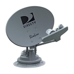
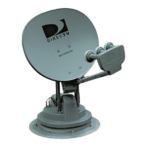
DIRECTV®Slimline Replacement
Back-up and Feed Arm Assembly
For help, email [email protected] or call 1-800-788-4417
www.winegard.com/mobile
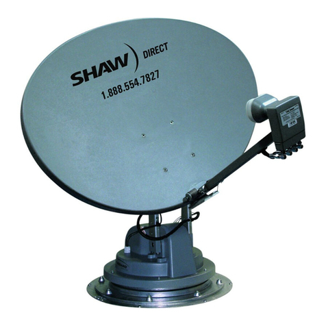
Automatic Multi-Satellite TV Antenna
Reflector bracket
Stiffener plate
Skew
housing
Feed arm
LNB guard
LNB
4
3 2
1
8
7
6
543
1
Bottom slot
of reflector bracket
Stiffener plate
Reflector bracket
2
Adapter plate
(behind reflector bracket)
*Approximate
location of post
on back side
1
2
3
Adapter plate
4
5
6
78
*
Four nuts and
bolts holding
LNB guard to
feed arm
Two screws holding
LNB to feed arm
Model
SK-SWM3
shown
1. Press and hold “POWER” for two seconds to turn on the
interface box. Wait until the interface box finishes “connecting
to antenna.” The antenna may enter the search routine after ten
seconds. Pay attention to the pinch points as the antenna raises!
2. Wait until the antenna has at least raised to a position
in which the LNB arm is parallel to the roof. Then, press
“POWER” and “SELECT” at the same time. The antenna
should stop moving.
3. Unplug the interface box.
4. Remove the four reflector nuts and bolts with a ½″wrench,
and remove the reflector. Discard the reflector, nuts, and bolts.
5. Remove and set aside the
four nuts and bolts holding
the LNB guard to the feed
arm. Then, slide the LNB
guard down the feed arm
and toward the reflector.
6. Remove and set aside the
two screws holding the
LNB to the feed arm.
7. Carefully slide the LNB out from the feed arm.
Disconnect the coax cable from the LNB using a
7/16″wrench, and set aside the LNB.
8. Once the LNB has been
removed, remove the LNB
guard from the feed arm.
9. If there is not already a line marking the top of the stiffener
plate, draw a line to mark the top of the stiffener plate.
10. Using a ½″wrench, loosen and remove the four bolts
holding the reflector bracket and stiffener plate to the skew
housing. At the same time, carefully remove the stiffener
plate and LNB arm assembly. Set aside the stiffener plate
and four bolts; you will need these later.
11. Identify the fourth outer hole
in the adapter plate. See
numbered holes to right. The
fourth hole marks the bottom
of the adapter plate.
Note: as the antenna raises and turns, the adapter plate may become
skewed, and the fourth hole may not be directly at the bottom of the plate.
If unsure of the fourth hole, remove the four screws from the center of the
adapter plate; a small post is located directly above the fourth hole.
12. Position the reflector bracket against the adapter plate. Make
sure the fourth outer hole in the adapter plate is centered in the
bottom slot of the reflector bracket. The third and fifth outer
holes should be close to opposite edges of the bottom slot.
13. Place the stiffener plate inside the reflector bracket. Make
sure the second and third outer holes in the stiffener plate
are centered in the bottom slot of the reflector bracket (see
above). The second and third outer holes in the stiffener plate
should additionally align with the third and fifth outer holes in
the adapter plate.
14. Install bolts through the four outer holes in the stiffener plate,
and tighten.
15. Slide the LNB guard onto the feed arm.
16. Run the sheathed cable through the feed arm and connect the
cable running through the feed arm to the LNB. Tighten the
cable until fingertight, and then use a 7/16″wrench to tighten a
quarter turn more. Do not overtighten.
17. Slide the LNB into the feed arm, and re-install the two screws
(removed earlier) through the underside of the feed arm and
replacement LNB. Tighten.
18. Slide the LNB guard up the feed arm and over the LNB. The
front of the LNB guard shoud be ~½″in front of the LNB and
should not be touching the LNB. Install the four bolts through
the four holes in the LNB guard. Thread a nut onto each bolt,
and tighten.
19. Slide the new reflector on to the lower hooks of the bracket,
ensuring that the upper holes on the reflector line up with the
upper holes on the reflector bracket. Insert two bolts through
the upper holes on the front of the reflector through the upper
holes on the bracket. Thread a nyloc nut on each bolt, and
tighten the nuts.
WARNING: Do not use old reflector hardware to install new reflector.
Failure to use new bolts/nyloc nuts can lead to property damage, personal
injury, and/or death.
20. Plug in the interface box. Press and hold “POWER” for two
seconds to turn on the interface box. Press “POWER” again to
stow the antenna.
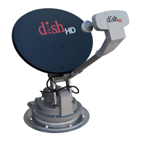
Instructions for Model RP-SK81
DISH®1000 Replacement
Back-up and Feed Arm Assembly
For help, email [email protected] or call 1-800-788-4417
www.winegard.com/mobileAutomatic Multi-Satellite TV Antenna
Winegard and TRAV’LER are registered trademarks of Winegard Company.
DIRECTV is a registered trademark of DIRECTV, LLC.
DISH is a registered trademark of Dish Network L.L.C.
Winegard Company • 3000 Kirkwood Street • Burlington, IA 52601
800-288-8094 • Fax 319-754-0787 • www.winegard.com
Printed in U.S.A. ©2013 Winegard Company Rev1 3-16 2452311
1
2
3
4
1
2
3
4
Reflector bracket
1
2
3
4
Adapter plate
Screws removed
from wider end of
integrated adapter
LNB slid out from
integrated adapter
Integrated
adapter
1. Press and hold “POWER” for two seconds to turn on the
interface box. Wait until the interface box finishes “connecting
to antenna.” The antenna may enter the search routine after ten
seconds. Pay attention to the pinch points as the antenna raises!
2. Wait until the antenna has at least raised to a position
in which the LNB arm is parallel to the roof. Then, press
“POWER” and “SELECT” at the same time. The antenna
should stop moving.
3. Unplug the interface box.
4. Remove the four reflector nuts and bolts with a 7/16″wrench,
and remove the reflector. Set the reflector, nuts, and bolts
aside; you will need these later.
5. Remove and set aside the four nuts and bolts holding the LNB
guard to the feed arm. Then, slide the LNB guard down the
feed arm and toward the reflector.
6. Remove and set aside the
two screws from the wider
end of the underside of the
integrated adapter.
7. Carefully slide the LNB out
from the integrated adapter.
Disconnect the three coax
cables from the LNB
using a 7/16″wrench,
and set aside the LNB.
8. Remove the two screws from the narrower end of the
integrated adapter, and gently pull apart the integrated adapter.
9. After removing the integrated adapter from the feed arm,
remove the LNB guard from the feed arm.
10. Using a ½″wrench, remove and set aside the four bolts from
the reflector bracket, and remove the feed arm assembly.
11. Align the four holes on the inside of the reflector bracket with the
four marked holes in the adapter plate. See marked holes below.
12. Install bolts through the four
aligned holes in the adapter plate
and reflector bracket, and tighten.
Note: the reflector bracket
should be positioned with
the feed arm assembly at the
bottom of the adapter plate
(near the third hole).
13. Slide the LNB guard onto the feed arm.
14. Position the integrated adapter on the feed arm. Make sure
that the two posts on the bottom of the integrated adapter
have been inserted into the two holes in the feed arm. The
integrated adapter should slant upwards.
15. Insert the two screws (removed earlier) through the holes in
the bottom of the integrated adapter and feed arm. Thread a
nut onto each bolt, and tighten.
16. Run the sheathed cable through the feed arm.
17. Connect the cables running through the feed arm to ports 1–3
(in any order) on the LNB. Tighten each cable until fingertight,
and then use a 7/16″wrench to tighten a quarter turn more. Do
not overtighten.
18. Slide the LNB into the integrated adapter, and re-install the
two screws (removed earlier) through the wider end of the
underside of the integrated adapter. Tighten.
19. Slide the LNB guard up the feed arm and over the LNB. The
front of the LNB guard should be ~½″in front of the LNB and
should not be touching the LNB. Install the four bolts through
the four holes in the LNB guard. Thread a nut onto each bolt,
and tighten.
20. Install the reflector bolts through the four corresponding holes
in the reflector and reflector bracket. Install the reflector nuts,
and tighten.
21. Plug in the interface box.
22. Press and hold “POWER” for two seconds to turn on the
interface box. Then, press “POWER” again to stow the antenna.
Other Winegard TV Antenna manuals

Winegard MS-3005 User manual

Winegard

Winegard MS-3005 User manual

Winegard HD-7015 User manual

Winegard

Winegard HD-7015 User manual

Winegard TRAV'LER DIRECTV SK-SWM3 User manual

Winegard

Winegard TRAV'LER DIRECTV SK-SWM3 User manual

Winegard BMK-300 User manual

Winegard

Winegard BMK-300 User manual

Winegard ROADSTAR RS3460B User manual

Winegard

Winegard ROADSTAR RS3460B User manual

Winegard Freevision FV-HD30 User manual

Winegard

Winegard Freevision FV-HD30 User manual

Winegard GM-1518 User manual

Winegard

Winegard GM-1518 User manual

Winegard SENSAR VM-2200 User manual

Winegard

Winegard SENSAR VM-2200 User manual

Winegard SK-3003 User manual

Winegard

Winegard SK-3003 User manual

Winegard HD9095P User manual

Winegard

Winegard HD9095P User manual

Winegard SK-3005 User manual

Winegard

Winegard SK-3005 User manual

Winegard MS-1002 User manual

Winegard

Winegard MS-1002 User manual

Winegard FV-HDCO User manual

Winegard

Winegard FV-HDCO User manual

Winegard Trav'ler Pro SK2SWM3 User manual

Winegard

Winegard Trav'ler Pro SK2SWM3 User manual

Winegard FreeVision User manual

Winegard

Winegard FreeVision User manual

Winegard SENSAR GS-2200 User manual

Winegard

Winegard SENSAR GS-2200 User manual

Winegard HD7084P User manual

Winegard

Winegard HD7084P User manual

Winegard Pathway X2 for Dish User manual

Winegard

Winegard Pathway X2 for Dish User manual

Winegard GM-1518 User manual

Winegard

Winegard GM-1518 User manual

Winegard SS-3000 User manual

Winegard

Winegard SS-3000 User manual

Winegard SharpShooter SS-3000 User manual

Winegard

Winegard SharpShooter SS-3000 User manual

Winegard HD-9032 User manual

Winegard

Winegard HD-9032 User manual

Winegard Trav'ler Pro SK2DISH User manual

Winegard

Winegard Trav'ler Pro SK2DISH User manual

Winegard RoadStar RS-3000 User manual

Winegard

Winegard RoadStar RS-3000 User manual

Popular TV Antenna manuals by other brands

Philex 27795R user guide

Philex

Philex 27795R user guide

August DTA415 user manual

August

August DTA415 user manual

Radio Shack 15-1634 owner's manual

Radio Shack

Radio Shack 15-1634 owner's manual

King Quest VQ4100 owner's manual

King Quest

King Quest VQ4100 owner's manual

Glomex DANUBE 2 R500S2 User and installation manual

Glomex

Glomex DANUBE 2 R500S2 User and installation manual

Audiovox AN300 user guide

Audiovox

Audiovox AN300 user guide

Philips US2-PHDTV1 Specifications

Philips

Philips US2-PHDTV1 Specifications

Alcad MX-047 manual

Alcad

Alcad MX-047 manual

Philips SDV8625T/55 user manual

Philips

Philips SDV8625T/55 user manual

Philips US2-MANT940 Specifications

Philips

Philips US2-MANT940 Specifications

Sphere SSA-850 Service manual

Sphere

Sphere SSA-850 Service manual

REMO Electronics BAS-1318 GALAXY Series Quick user guide

REMO Electronics

REMO Electronics BAS-1318 GALAXY Series Quick user guide

THOMSON ANT1418BK operating instructions

THOMSON

THOMSON ANT1418BK operating instructions

TERK Technologies MTVGLS quick start guide

TERK Technologies

TERK Technologies MTVGLS quick start guide

BAS 5107 MiniDigital Quick user guide

BAS

BAS 5107 MiniDigital Quick user guide

Terrestrial Digital Lacrosse Assembly instructions

Terrestrial Digital

Terrestrial Digital Lacrosse Assembly instructions

Radio Shack 1500254 user guide

Radio Shack

Radio Shack 1500254 user guide

IKUSI Flashd LTE c60 manual

IKUSI

IKUSI Flashd LTE c60 manual

manuals.online logo
manuals.online logoBrands
  • About & Mission
  • Contact us
  • Privacy Policy
  • Terms and Conditions

Copyright 2025 Manuals.Online. All Rights Reserved.