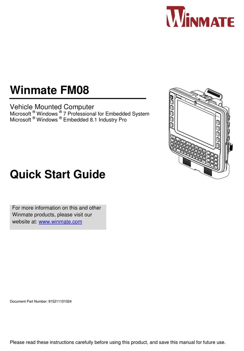
Winmate FM08 User manual

Winmate FM08
Vehicle Mounted Computer
Microsoft ®Windows ®7 Professional for Embedded System
Microsoft ®Windows ®Embedded 8.1 Industry Pro
Quick Start Guide

1
FM08 Quick Start Guide
About This Guide
This guide contains the following:
Contents
About This Guide 1
i. Features 2
ii. Unpacking 3
iii. Docking and Undocking the Device 4
a. Dock the device into vehicle dock 4
b. Undock the device 4
iv. Cabling Installation 5
a. Connecting the power cable for office testing 5
b. Connecting the power cable on the vehicle 6
v. Power On Behavior 8
a. Power Button 9
b. Standby / Wakeup Behavior 9
vi. Defroster 10
vii. Antenna Installation 12
viii. RAM Mounts Installation 13
a. Component of RAM Mounts kits 13
b. RAM Mounts assembly 13
c. Keyboard Mounting Installation 14
For more detail information about this device, please refer to the FM08 User Manual available at
http://www.winmate.com/

2
FM08 Quick Start Guide
i. Features

3
FM08 Quick Start Guide
ii. Unpacking
Computer FM08
Dock with latch locking key
Power cable (5 m) with 2 x fuse kit
USB Cable (0.3 m)
Stylus Kit with Screw
Cable clamp kit
2 x WiFi External Antenna
Quick Start Guide and Driver CD
Power cable for Testing*

4
FM08 Quick Start Guide
Note
Users are highly recommended to purchase this power cable for
testing purpose
iii. Docking and Undocking the Device
a.Dock the device into vehicle dock
To dock the device, perform the following:
1. With the device screen side facing out, align and insert the device into the guide pins on
the vehicle dock.
2. Push the device against the dock to ensure the terminal contacts are properly connected.
3. Secure the device by pulling the latch forward until a “click” is heard, indicating the latch is
fully engaged.
b.Undock the device
To undock the device from the vehicle dock, perform the following:
1. While supporting the device with one hand, push the latch backward until it fully
disengaged.
2. Remove the device from the vehicle dock.
1.
2.
3.
1.
2.

5
FM08 Quick Start Guide
iv. Cabling Installation
Warning
This procedure require a trained service personnel only,
improper installation can cause serious damage to the vehicle
or the device
a.Connecting the power cable for office testing
Note
Users are highly recommended to purchase this power cable for
testing purpose
1. Place the device on the vehicle dock and make sure the device is Off
2. Connect the CN2 to the FM08 vehicle dock by aligning the connector pins and then push it,
twist to fasten the connection.
3. Connect the AC plug to the electrical outlet
* The Positive (+) and Ignition is
connected inside the cable

6
FM08 Quick Start Guide
4. Switch the power switch On, located on the back of the vehicle dock
5. Press the On button, the device is ready for testing
b.Connecting the power cable on the vehicle
Warning
This power cable should only be used on the 12, 24, 36, or 48
Volt forklifts.
Warning
Select a mounting location and make sure it is not located on
the outside the vehicle
Color
Symbol
Red
VCC+
Black
VCC-
Green
Ground
Blue
Ignition input (optional)
Warning
Do not perform the installation on a moving or live electric
forklift
1. Remove the vehicle battery before connecting the power cable
2. Connect the Green Wire (Ground) to the vehicle‟s chassis (grounding), which can also
be negative pole of the battery. See diagram 6-1 and 6-2
3. Place the fuse and fuse holder in-line of the Red (VCC +) and Blue (ignition) wires as
shown below.

7
FM08 Quick Start Guide
Fuse Specification :
Two Fuses , 15A, 250Volt, UDA Type Fuses
Warning
All power wiring must use the supplied power cable
4. Slide tubing over wires , remove the wires and insert it to the fuse holder, crimp it
5. Connect the red wire to the vehicle‟s positive power source. Connect the black wire to
the vehicle‟s negative power source.
6.1Connect the blue wire to the vehicle‟s ignition switch for the ignition function
Diagram 6.1 With Ignition Function
6.2The ignition cable (Blue cable) must be connected to the battery positive if the
customer does not want to have ignition function , as following
Diagram 6.2 Without Ignition Function

8
FM08 Quick Start Guide
7 Secure the power cable to the device using cable clamps and place the device in the dock.
See Power cable routing below
Warning
Use the proper cable clamps and not to over tighten it to
prevent it from break
8 Press the power switch on the back of the dock See Power switch
9 Press the power button on the front of the device See Power Button
v. Power On Behavior
The Following table shows the Ignition control power scheme on the vehicle installation and
office test.
Power On
Behavior
Office Test / Evaluation
Vehicle Installation
With Ignition
Without Ignition
Ignition delay
Default „”0 second”
Default „”0 second”
Default „”0 second”
Adjustable from 0-120 Second, through AP. See AP for Ignition below
Auto-ON
OFF, can be disable
through BIOS Switch
ON
ON
Power Button
√
X
X

9
FM08 Quick Start Guide
AP for Ignition Delay
a.Power Button
The Power button is located at lower right of
the FM08
Note
• The FM08 need to be docked in a powered
vehicle dock or UPS battery has a sufficient
charge to power the device.
• If no external power available and the UPS
battery does not have enough charge,
pressing the power button will cause no
action
Action
Button
Power Button
Backlight
Indicator
Turn On
Press the On button for “2 seconds”
until the battery indicator On (solid
green) and then release the button
Off
b.Standby / Wakeup Behavior

10
FM08 Quick Start Guide
Action
Button
Power Button
Backlight
Indicator
Standby or
Sleep Mode *
Press the On button for “2 seconds”
until the screen On and then release
the button. The battery indicator will
Off after the screen is Off, the
system is already in the standby /
sleep mode
On
Wake up
Press the On button for “2 second”
until the screen On and then release
the button. The battery indicator will
On (solid green)
Off
Turn Off
Press the On button for “4 second”
until the system is turns Off and
then releases the button.
Off
*This behavior mode can be configured on the Power and Sleep Button Settings,
Start > Control Panel > Power Options > Choose what the power buttons do
vi. Defroster
Warning
The defroster is always disable when the device is operating
from UPS battery power
1. To show the defroster status tap and this screen below shows the information about the
defroster

11
FM08 Quick Start Guide
2. The default status of Defroster is Enabled in the auto on mode
3. Depending on the defroster trip point, to trigger the Defroster ON, the defroster on trip point
need to be lower than 0 or 5 deg. C. The defroster on trip point default is “0” and can be
configurable as follow :
4. To trigger the Defroster OFF, the Defroster off trip point needs to be higher than 10 deg. C or
15 deg. C. The defroster off trip point is configurable as follow :
5. To disable or turn off the defroster, tap the disabled button. This will make the defroster is Off
in any condition
When the Defroster is ON, a
heater indicator in the lower
right corner of the device
will show Red Color
When the Defroster is OFF,
a heater indicator in the
lower right corner of the
device will Turn off

12
FM08 Quick Start Guide
vii. Antenna Installation
The FM08 vehicle dock is equipped with SMA Connector for additional external antenna (WiFi or
optional WWAN), to install the Antenna please perform the following:
1. Remove the rubber cap on the SMA connector before installing the antenna
2. Align the antenna with the SMA connector and fasten it as following picture
3. The external antennas are adjustable as following
WiFi Antenna Installation
WiFi and WWAN Antenna Installation

13
FM08 Quick Start Guide
viii. RAM Mounts Installation
a.Component of RAM Mounts kits
The docking of this device is designed to be mounted to RAM Mount solutions, which provides
various types of mount types to fit any industrial use or vehicle. Each mounting kit consists of:
No
Component
Winmate Part
Number
RAM Mounts
Part Number
Description
A
RAM Clamp Mounts - on
the forklift
9B000000007T
RAM-D-247U-4
Clamp base with
2.25” Ball
B
RAM Arm
9B000000007S
RAM-D-201U
Arm for 2.25” Ball
(L:8.375”)
C
RAM Ball on the device
side
9B000000007U
RAM-D-2461U
75x75mm VESA
with 2.25” Ball
C-1
Screw
913511101149
--
SUS304 M5 x
12mm Screw
C-2
Washer
91351110111Y
--
M5 Washer
b.RAM Mounts assembly
Step 1. Install RAM Clamp to vehicle or forklift
1.1 Determine the position for mounting the RAM clamp mount according to RAM Mounts
installation guide and specification

14
FM08 Quick Start Guide
1.2 Place the upper clamp with ball on the beam, insert the bolt
1.3 Place the lower clamp below the beam, align the bolts with the holes in the lower clamp
1.4 Place the nuts and then tighten the
Step 2. Install RAM Ball base to vehicle dashboard / other surface
2.1 Please make sure that the surface is flat and rigid
2.2 Attach the RAM ball base to the vehicle and fix it using bolt or fasteners.
Step 3. Attach RAM Mount Ball to the device docking
3.1Turn the device off before installing the RAM mount ball
3.2Locate the VESA mount holes on the back of the device and align it with the holes from
RAM Ball base.
3.3Attach with four M5 screws
Step 4. Attach the device to RAM arm
4.1Insert the RAM arm over the ball on the vehicle RAM mount (shown here)
4.2Insert the ball on the dock into the RAM arm and tighten the knob
c.Keyboard Mounting Installation

15
FM08 Quick Start Guide
No
Component
Winmate Part
Number
RAM Mounts
Part Number
Description
D
Winmate Keyboard adapter
plate (designed by Winmate)
821009131600
--
4 VESA Holes on
the plate to device
and 4 AMPS holes
to RAM Ball
D-1
Screw
913511101149
--
SUS304 M5 x
12mm Screw
D-2
Washer
91351110111Y
--
M5 WASHER
E
RAM Ball on the sloped part
of the keyboard adapter plate
9B000000007P
RAM-202U
2.5" Round Base
with 1.5" Ball
E-1
Screw
91351110111W
--
SUS304 M4 x
14mm Screw
E-2
Washer
91351110111X
--
M4 WASHER
F
RAM Arm
9B000000007Q
RAM-201U
Arm for 1.5" Ball
(Length:5.6")
G
RAM Ball on the sloped part
of the keyboard adapter plate
9B000000007P
RAM-202U
2.5" Round Base
with 1.5" Ball
This part shows the steps to install the keyboard.
1. Fasten all four screws on the RAM mount ball on the back of the keyboard
2. Fasten the keyboard adapter on the other end of the RAM mount ball.
3. Fasten the RAM mount ball screws on the back of the device, so all mounting parts are fasten
together.

16
FM08 Quick Start Guide
Copyright © 2015 Winmate Communication Inc. All rights reserved.
No part of this manual may be reproduce, copied, translated, or transmitted in any form or any
means, electronic or mechanical, for any purpose, without the written permission of Winmate
Communication Inc.
Trademarks
All product names, trademarks or logos mentioned herein are the properties of their respective
owners.
Microsoft, Windows, and the Windows logo are either registered trademarks or trademarks of
Microsoft Corporation in the United States and/or other countries. Microsoft products are licensed
to OEMs by Microsoft Licensing, Inc., a wholly owned subsidiary of Microsoft Corporation.
The Bluetooth® word mark and logos are registered trademarks owned by Bluetooth SIG, Inc.
All other brand and product names are trademarks or registered trademarks of their respective
owners.
NOTE:
Display images shown may vary slightly from actual display. Information in this
manual is subject to change without notice.
Disclaimer
Winmate Communication Inc. reserves the right to make any product changes without notice,
including circuits and/or software described or contained in this manual in order to improve
design and/or performance. Winmate Communication Inc. assumes no responsibility or liability
for the use of the described product(s), conveys no license or title under any patent, copyright, or
masks work rights to these products, and makes no representations or warranties that these
products are free from patent, copyright, or mask work right infringement, unless otherwise
specified. Applications that are described in this guide are for illustration purposes only. Winmate
Communication Inc. makes no representation or warranty that such application will be suitable
for the specified use without further testing or modification.
Warranty
Winmate Communication Inc. warrants that each of its products is free from material and
workmanship defect for a period of one year starting from the invoice date. If the customer
discovers a defect, Winmate Communication Inc. will, at its option, repair or replace the defective
product at no charge to the customer, provided it is returned during the warranty period, with
transportation charges prepaid. The returned product must be properly packaged in its original
packaging to obtain warranty service.
Other manuals for FM08
2
Table of contents
Other Winmate Automobile Accessories manuals

Winmate
Winmate FM08 User manual

Winmate
Winmate FM07 User manual

Winmate
Winmate FM10Q User manual

Winmate
Winmate FM10A User manual

Winmate
Winmate FM07A User manual

Winmate
Winmate FM10 User manual

Winmate
Winmate FM07 User manual

Winmate
Winmate G-WIN User manual

Winmate
Winmate FM10 Installation and operation manual
Winmate
Winmate FM10A Installation and operation manual