Winston PRO 20 EVI Quick guide

HIGH PERFORMANCE
INVERTER HEATER PRO 20 EVI
Installation and Instruction Manual

CONTENT
1 Preface 1
2 Safety Precaution 2
(1)
Mark notes 2
(2)
Icon Notes 2
(3)
Warning 3
(4)
Attention 4
3 Specification 5
(1)
Appearance and structure of the heat pump 5
(2)
The data of unit 6
(3)
Unit dimension 7
4 Installation 9
(1)
Application ofheat pump 9
(2)
Choose a right heat pump unit 10
(3) Installation place 10
(4)
Installation method 10
(5)
Water loop connection 11
(6)
Power supply connection 11
(7)
Location ofthe unit 11
(8)
Transit 12
(9)
Trial Running 12
5 Operation and Use 13
(1)
Main interface display and function
13
(2)
Parameter list andbreakdown table
24
(3)
Interface diagram
26
6 Appendix 29
(1)
Appendix 1 29
(2)
Appendix 2 30
(3)
Appendix 3 31
(4)
Appendix 4
31
(5)
Appendix 5 32
(6)
Appendix 6 33

Preface
1
In order to provide the customers with high quality, strong reliability and good versatility
product, this heat pump is produced by strict design and manufacture standards.
This manual includes all the necessary information about installation, debugging,
discharging and maintenance. Please read this manual carefully before you open or
maintain the unit.
The manufacture of this product will not be held responsible if someone is injured or
the unit is damaged, as a result of improper installation, debugging, unnecessary
maintenance which is not in line with this manual.
The unit must be installed by qualifiedpersonnel.
It is vital that the below instructions are adhered to at all times to keep the warranty.
—The unit can only be opened or repaired by qualified installer or an authorised dealer.
—Maintenance and operation must be carried out according to the recommended time and
frequency, as stated in this manual.
—Use genuine standard spare parts only.
Failure to comply with these recommendations will invalidate the warranty.
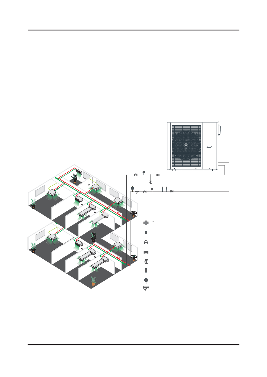
Inverter air source water heat pump is a kind of high efficiency, energy saving and environment
friendly equipment, which is mainly used for house warming. It can work with any kind of indoor
unit such fan coil, radiator, or floor heating pipe, by provide warm or hot water. One unit of
monobloc heat pump can also work with several indoor units.
The air source water heat pump unit is designed to have heat recovery by using super
heater which can provide hot water for sanitary purpose.
This series of heat pump unit owns following features:
1
Advanced controlling
The PC microcomputer based controller is available for the users to review or set the
running parameters of the heat pump. Centralized controlling system can control several units by
PC.
2
Nice appearance
The heat pump is designed with beautiful looking. The monobloc one has the water pump
included which is very easy for installation.
3
Flexible installation
The unit has smart structure with compact body, just simple outdoor installation is needed.
4
Quiet running
High quality and efficient compressor, fan and water pump is used to ensure the low noise
level with insulation.
5
Good heat exchange rate
The heat pump unit use special designed heat exchanger to enhance whole efficiency.
6
Large working range
This series of heat pump is designed to work under different working conditions as low as -15
degrees for heating.

2
Safety Precaution
Mark Notes
Icon notes
To prevent the users and others from the harm of this unit, and avoid
damage on the unit or other property, and use the heat pump properly,
please read this manual carefully and understand the following
information correctly.
Mark
Meaning
WARNING
A wrong operation may lead to death or heavy injury on
people.
ATTENTION
A wrong operation may lead to harm on people or loss of
material.
Icon
Meaning
Prohibition. What is prohibited will be nearby this icon
Compulsory implement.The listed action need to be taken.
ATTENTION (include WARNING)
Please pay attention to what is indicated.

3
Safety Precaution
Installation
Meaning
Professional installer is
required.
The heat pump must be installed by qualified personals, to
avoid improper installation which can lead to water leakage,
electrical shock or fire.
Earthing is required
Please make sure that the unit and power connection
have good earthing, otherwise may cause electrical shock.
Operation
Meaning
PROHIBITION
DO NOT put fingers or others into the fans and evaporator of
the unit, otherwise harm may be occurred.
Shut off the power
When there is something wrong or strange smell, the power
supply need to be shut off to stop the unit. Continue to run may
cause electrical short or fire.
Move and repair
Meaning
Entrust
When the heat pump need to be moved or installed again,
please entrust dealer or qualified person to carry it out.
Improper installation will lead to water leakage, electrical
shock, injury or fire.
Entrust
It is prohibited to repair the unit by the user himself,
otherwise electrical shock or fire may be occur.
Prohibit
When the heat pump need to be repaired, please entrust dealer
or qualified person to carry it out. Improper movement or repair
on the unit will lead to water leakage, electrical shock, injury or
fire.
Do not use means to accelerate the defrosting process or to
clean,Other than those recimmended by the manufacturer.
The appliance shall be stored in a room without continuously
operating ignition sources (for example:open flames, an operating
gas appliance or an operating electric heater.)
Warning

4
Safety Precaution
Installation
Meaning
Installation Place
The unit CANNOT be installed near the flammable gas.
Once there is any leakage of the gas, fire can be occur.
Fix the unit
Make sure that the basement of the heat pump is strong
enough, to avoid any decline or fall down of the unit
Need
circuit breaker
Make sure that there is circuit breaker for the unit, lack of
circuit breaker can lead to electrical shock or fire.
Operation
Meaning
Check the
installation basement
Please check the installation basement in a period (one
month), to avoid any decline or damage on the basement,
which may hurt people or damage the unit
Switch off
the power
Please switch off the power for clean or maintenance.
Prohibition
It is prohibited to use copper or iron as fuse. The right fuse
must be fixed by electrician for the heat pump.
Prohibition
It is prohibited to spray the flammable gas to the heat pump,
as it may cause fire.
ATTENTION

5
Specification
1. Appearance and structure of the heat pump
Wi3-20-114-PH-EVI-32
Air outlet in horizontal
direction The longest distance of installing the
remote controller is 200 meters.
Water outlet tube
Water intlet tube
Remote Controller
(Manually)

6
Specification
2. The data of unit
Cooling working condition: (DB/WB) 35°C/24°C, (outlet/inlet) 7°C/12°C.
Heating working condition: (DB/WB) 7°C/6°C, (outlet/inlet) 35°C/30°C.
BS EN 14511-1-2013 Air conditioner, whole liquid cooling machine, electric compressor. Part2:
Test condition Part3:Test method Part4:related requirements.

7
Specification
3. Unit dimension
Model: Wi3-20-114-PH-EVI-32
Water outlet 1 1/4''
Water inlet 1 1/4''
125
55
650
1040
1030
437
395
1315

Installation
9
Unit features
1. Plate heat exchanger
Use the SWEP efficient heat exchanger with small size and high efficiency.
2.Environmentally friendly refrigerant
Use the new generation of environmentally friendly refrigerant R32, which is harmless to
the ozone
sphere.
3. Heating in frigid environment.
Optimized designed unit can achieve the heating function normally even when the ambient
temperature is -15°C.
1 Application of heat pump
1.1 Only for air-con
WATER COUPLING
AUTOMATIC AIR VENT
CHECK-VALVE FOR WATER
FLEXIBLE CONNECTION FOR WATER
DIRTY DRAIN
WATER THERMOMETER
WATER PRESSURE METER
WATER FILTER

Installation
10
2
Choose a right heat pumpunit
Based on the local climate condition, construction features and insulation level,
calculate the required cooling(heating) capacity per square meter.
Conclude the total capacity which will be needed by the construction.
According to the total capacity needed, choose the right model by consulting the heat.
pump features as below:
Heat pump features
Cooling only unit:chilled water outlet temp. at 5-15℃, maximum ambient temp. at 43℃.
Heating and Cooling unit:for cooling chilled water outlet temp. at 5-15℃,maximum ambient
temp. at 43℃. For heating, warm water inlet temp. at 40-50℃, minimum ambient temp. at -10℃.
Unit application
Inverter air source water heat pump is used for house, office, hotel, and so forth, which need
heating or cooling separately, with each area need to be controlled.
3
Installation place
The unit can be installed on any place outdoor which can carry heavy machine such
as terrace, housetop, ground and soon.
The location must have goodventilation.
The place is free from heat radiation and other fire flame.
A pall is needed in winter to protect the heat pump from snow.
There must be not obstacles near the air inlet and outlet of the heat pump. A
place which is free from strong air blowing.
There must be water channel around the heat pump to drain the condensing water .
There must be enough space around the unit for maintenance.
4
Installation method
The heat pump can be installed onto the concrete basement by expansion screws, or onto
a steel frame with rubber feet which can be placed on the ground or housetop.
Make sure that the unit is placed horizontally.

Installation
11
5
Water loop connection
Please pay attention to below matters when the water pipe is connected: Try
to reduce the resistance to the water from the piping.
The piping must be clear and free from dirty and blocks. Water leakage test must be
carried out to ensure there is no water leaking. And then the insulation can be made.
Attention that the pipe must be tested by pressure separately. DO NOT test it together with
the heat pump.
There must be expansion tank on the top point of the water loop, and the water level in the
tank must be at least 0.5 meter higher than the top point of the water loop.
The flow switch is installed inside of the heat pump, check to ensure that the wiring and
action of the switch is normal and controlled by the controller.
Try to avoid air stayed inside of the water pipe, and there must be air vent on the top point
of the water loop.
There must be thermometer and pressure meter at the water inlet and outlet, for easy
inspection during running.
6
Power supply connection
Open the front panel, and open the power supply access.
The power supply must go through the wire access and be connected to the power
supply terminals in the controlling box. Then connect the 3-signal wire plugs of the wire
controller and main controller.
If the outside water pump is needed, please insert the power supply wire into the wire
access also and connect to the water pump terminals.
If an additional auxiliary heater is need to be controlled by the heat pump controller, the
relay (or power) of the aux-heater must be connected to the relevant output of
the controller.
7
Location of the unit

Installation
12
8
Transit
When the unit need to be hung up during installation, a 8
meters cable is needed, and there must be soft material
between the cable and the unit to prevent damage to the
heat pump cabinet. (See picture 1)
Picture 1
9
Trial Running
Inspection before trial running
Check the indoor unit, and make sure that the pipe connection is right and the relevant valves
are open .
Check the water loop, to ensure that the water inside of the expansion tank is enough, the water
supply is good, the water loop is full of water and without any air. Also make sure there is good
insulation for the water pipe.
Check the electrical wiring. Make sure that the power voltage is normal, the screws are
fastened, the wiring is made in line with the diagram, and the earthing is connected.
Check the heat pump unit including all of the screws and parts of the heat pump to see if they
are in good order. When power on, review the indicator on the controller to see if there is any
failure indication. The gas gauge can be connected to the check valve to see the high
pressure(or low pressure) of the system during trial running.
Trial running
Start the heat pump by press " " key on the controller. Check whether the water pump is
running, if it runs normally there will be 0.2 MPa on the water pressure meter.
When the water pump runs for 1 minutes, the compressor will start. Hear whether there is
strange sound from the compressor. If abnormal sound occurs please stop the unit and check
the compressor. If the compressor runs well please look for the pressure meter
of the refrigerant.
Then check whether the power input and running current is in line with the manual. If not
please stop and check.
Adjust the valves on the water loop, to make sure that the hot(cool) water supply to each door
is good and meet the requirement of heating(or cooling).
Review whether the outlet water temperature is stable.
The parameters of the controller are set by the factory, it is not allowed to change then by
user himself.
DO NOT touch the heat exchanger of the heat pump with fingers or other objects!
WARNING

Operation and Use
1. Main interface display andfunction
13

Operation and Use
14
Key function
Key number
Key name
Key function
①
On and off
Click this key to switch ON or OFF
Red represents ON, while grey represents OFF
②
Mode key
Hot water mode, heating mode, cooling mode,
hot water+heating mode or hot water+cooling mode can
be selected by pressing this key.
③
Temperature
setting
Click this key to set the target temperature
④
Lock screen
Click this key to lock the screen. White represents not
enabled, while green represents enabled
⑤
Timer setting
Click this key to set the timer. White represents not
enabled, while green represents enabled
⑥
Setup key
Click this key to check the unit status, time,factory
parameter, temperature curve, timer setting and Mute
setting
⑦
Fault icon
This Icon will flash when there is an error shown up, then
the display will enter failure record interface after tapping
this icon
Note:
⑧is defrosting icon, the machine is in defrosting mode when this icon is shown;
⑨is hot water mode icon, the machine is in hot water mode when this icon is shown;
⑩is cooling mode icon, the machine is in cooling mode when this icon is shown.

15
Operation and Use
1.1 On and off
As the main interface shows
(
1
)
.In shutting down interface (on/off key is in gray status),
press on/off key can start up the machine.
(
2
)
Note: In starting up interface (on/off key is in red status),
press on/off key can shut down the machine.
1.2 Mode switch

16
Operation and Use
In the main interface, there are five modes can be selected after tapping the mode key.
(1)
tapping hot water mode icon ①, then the display will change to this mode interface;
(2)
tapping heating mode icon ②, then the display will enter this mode interface;
(3)
tapping cooling mode icon ③,then the display will switch to this mode interface;
(4)
tapping hot water+heating mode icon ④, then the display will go
into hot water+heating mode interface;
(5)
tapping hot water+cooling mode icon ⑤, then the display will come to
hot water+cooling mode interface;
Note: If what you have purchased is a heating-only model (without cooling function), the
"cooling" will not be shown on the interface.
1.3 Setting of target temperature
Take hot water + cooling mode for example:
Tapping ①, the wire controller back to main interface;
Tapping ②, the target temp of hot water can be set by pop-up keyboard;
Tapping ③, the target temp of cooling mode can be set by pop-up keyboard.

17
Operation and Use
1.4 When the target temp is being set, pop-up keyboard is shown as
following:
Note: ①means the new target temp under current setting
1.5 Unlock screen
Click the lock screen key again while the screen has been locked, pop-up keyboard is
shown as following:

18
Operation and Use
②
③
Note: Input the password of 22 or 022, click the enter key and the screen will be
unlocked.
1.6 Timer setting
Click the timer setting key to enter the timer setting and the interface display is as
follows:
①④⑤
⑥⑦

Operation and Use
19
Key number
Key name
Key color
Key function
①
Return key
Click this key to return to the main
interface.
②
Enable the
timer on
Enable: Green ON
Disable: Gray OFF
Click this key to start or turn off the
timed start-up function
③
Enable the
timer off
Enable: Red ON
Disable: Gray OFF
Click this key to start or turn off the
timed shutdown function
④
Hour of timer on
Hour of Timer on is shown
⑤
Minute of
timer on
Minute of Timer on is shown
⑥
Hour of timer off
Hour of Timer off is shown
⑦
Minute of
timer off
Minute of Timer off is shown
Such as the above figure: Under the state of unmanned operation, it will start the timed start-
up at 17:10 and will be timed shutdown when running to 20:10 .
1.7 Setup
Click the setup key to enter the setup and the interface display is shown as follows:
①②③④
⑤⑥
This manual suits for next models
1
Table of contents
Popular Heater manuals by other brands

EWT
EWT NOCeco10TLS manual

HEATSTRIP
HEATSTRIP Classic THH1500AUL Operation, installation, and maintenance manual

Ayce
Ayce EH900 BALI Original instructions

Perel
Perel IH0004 user manual

NeoNail Professional
NeoNail Professional 4476 User manual description

Heatstore
Heatstore HS2020TXN operating instructions