Wisdom S55i User manual

Owner’s Manual
Wisdom Audio S55i
In-Wall Subwoofer

Table of Contents
Introduction....................................................................................................4
About this manual..................................................................................................4
Description .....................................................................................................5
Regenerative
Transmission Line™ ...............................................................................................5
Unpacking the S55i .........................................................................................6
Room Acoustics & Placement..........................................................................7
Start With the Room ..............................................................................................7
Rigid Walls......................................................................................................7
Speaker Placement.................................................................................................8
Left & Right Speakers ......................................................................................8
Center Channel...............................................................................................8
Remote Setup via Modem......................................................................................8
Surround Speakers..........................................................................................9
Subwoofer Placement ............................................................................................9
Room Treatment ..................................................................................................10
Professional Acoustic Design ...............................................................................10
References ........................................................................................................... 11
Installing the S55i in a Wall...........................................................................12
Installing the S55i in the Ceiling....................................................................14
Tips and Ideas......................................................................................................22
Black out the HVAC and snorkel...................................................................23
Limited access situations ...............................................................................24
Installing under the oor ...............................................................................24
North American Warranty ............................................................................26
Standard Warranty ...............................................................................................26
Harsh Conditions Use ..........................................................................................26
Obtaining Service .........................................................................................27
Specications................................................................................................28
S55i Dimensions............................................................................................29
Notes.............................................................................................................30


4
Introduction
Congratulations on purchasing your Wisdom Audio in-wall subwoofer. The
S55i’s Regenerative Transmission Line™technology delivers tremendous bass
performance in terms of depth, dynamics, and distortion resulting in articu-
late bass that integrates seamlessly with high-resolution main speakers such as
Wisdom Audio’s Insight Series.
About this manual This manual focuses on the S55i subwoofer itself. In order to fully understand
the system, we recommend you also review the manual for the SC-1 System
Controller, or SW-1 subwoofer amplier, or MiniDSP-1 subwoofer processor,
without one of which this subwoofer will not perform correctly.
While we expect your local Wisdom Audio dealer to take care of the setup and
calibration of the system, we still recommend that you at least briey review this
and the other manuals to understand the system’s full capabilities.

5
Description
Your Sage S55i subwoofer uses a modern implementation of an old idea for high
quality, low distortion bass reproduction. While the roots of the Regenerative
Transmission Line™go back to the 1950’s, it is the combination of modern com-
puter modeling and the vastly more powerful motors of contemporary driver
design that make the RTL™so special.
Regenerative
Transmission Line™
There is a class of bass enclosures that has been around since the 1950’s, which
can be described generically as “low frequency tapped waveguides” or “tapped
pipes.” It was an idea that was a bit ahead of its time then, since fully optimiz-
ing its use required both powerful drivers and computer modeling. But if you
are into such things, check out US Patent 2,765,864 (led in 1955), and an AES
paper published in 1959, “Analysis of a Low Frequency Loudspeaker System.”
We have published both on our website for your convenience, at
http://www.wisdomaudio.com/support_documents.php
We have utilized sophisticated modeling software in order to fully optimize our
enclosures, and have developed drivers that are specically optimized for this
application. We call our unique implementation of this relatively old idea a
“Regenerative Transmission Line™” subwoofer, or “RTL™” sub for short.
All dynamic drivers develop energy on both sides of the diaphragm, with the
rear energy being 180° out of phase with the front energy. If you allow the
driver to operate in free space (no enclosure), the front and rear energies largely
cancel each other out — especially at low frequencies.
In our Regenerative Transmission Line™subwoofer, the energy from the back
side of the driver is sent along a long, folded path in such a way that its lowest
frequencies arrive back at the front side of the driver in phase, effectively sum-
ming to an increase of 6 dB in output. Thus, the energy from both sides of the
woofer cone is used in a productive way, resulting in a substantial reduction in
distortion and an effective surface area double compared to what you would
otherwise expect. As an example, the effective radiating surface area in the S55i
is roughly equivalent to a 8” diameter round woofer, yet the enclosure ts in a
3.5” deep stud bay.
The results are quite striking. Low frequencies are dynamic and responsive, and
integrate quite seamlessly with the fast and detailed Sage Series planar magnetic
hybrids.

6
Unpacking the S55i
Please exercise caution when unpacking your S55i.
Caution! As shipped, a protective steel construction shield is held in place
magnetically to seal the S55i from various construction debris, paint,
etc. The grille is in a separate cardboard sleeve in the shipping
box. Please locate and save the grille for later use, leaving the
construction shield in place until you are ready to play the S55i.
The S55i is fully assembled on delivery. The front surface has a smooth, resin-
coated paper nish that can be taped and spackled, and then painted to match
the adjacent drywall (gypsum board).
The end of the speaker that contains the grille assembly also includes the “pig-
tail” for connecting the speaker to the system, as well as some “feet” to support
the S55i slightly above the sole plate, to allow room for the wiring and the base-
board of the nished wall. (Rooms with unusually tall baseboards may require
the S55i to be mounted somewhat higher still.)
The grille itself is held in place magnetically. Removing the grille exposes the
black service panel, which only needs to be removed in the unlikely case that
one or more drivers needed to be replaced after installation in the wall.
The Regenerative Transmission Line™ opening occupies less than half the space
covered by the grille. You can see the serial number of your S55i by removing
the grille and looking int the RTL opening; it will be on the back, inside surface
of the S55i enclosure.

7
Room Acoustics & Placement
Wisdom Audio believes in equalization. Assume for a moment that you had a
“perfect” loudspeaker: as soon as you place it in your room, its perfection is
gone. In fact, even good rooms can introduce deviations of 20 dB to the re-
sponse of the system. This is particularly true in the bottom two octaves, where
a subwoofer operates.
It seems strange to us to worry about tenths-of-a-decibel differences between
one component and another when there are 10-20 dB problems right there in
the room with you.
At the same time, room equalization is not a panacea. It does not solve all prob-
lems. In fact, and somewhat paradoxically, EQ works best when it has the least
to do. It is best used as the “nishing touch” on an otherwise good system. Un-
fortunately, most people do not understand that the most important component
in their system is their listening room.
This manual does not have the space for a full description of everything that
goes into creating excellent room acoustics; doing so would require a textbook
of several hundred pages. Instead, we will give you some ideas, and some refer-
ences to pursue should you want to learn more.
Start With the Room There are many myths oating around pertaining to what a “good room” should
be like. One of the most common is that it should have non-parallel walls. With-
out going into the details, we recommend staying with rectangular rooms whose
dimensions do not share common divisors.
Thus a room with dimensions of 8’ by 16’ by 20’ would be quite poor (since the
dimensions are all divisible by a length of 4’, and 16 is also a multiple of 8). By
contrast, a room whose dimensions are 9’ by 16’ by 29’ would be much better,
since none of the dimensions are mathematically related to one another.
There are innite variations on this idea. If you have the exibility to choose (or
modify) your room dimensions to avoid such problems, do so. Either way, ca-
pable room optimization will be a big help making the most of what you have.
Rigid Walls Another myth that should be dispelled is the notion that the walls (and ceiling
and oor) of the room should be extremely rigid in order to reproduce good
bass. Rigid, inexible walls reect energy extremely well; thus you will keep
more of the bass energy in the room. This much is true. However, those rigid
walls will only increase the amplitude of the standing waves that your room
naturally supports. In simple terms, you will have more bass, but it will also be
more irregular, with larger peaks and valleys in the response.
Walls that ex a bit (but do not rattle) are much better. Coincidentally, tradition-
al American residential construction standards (sheet rock on wooden studs) are
not a bad place to start. You can do better still with professional help, but studs
and sheet rock are better than poured concrete. (If your listening room is in the
basement, a false wall can easily be built in front of the concrete. You probably
need something like this for insulation and aesthetics anyway.)

8
The ultimate in dedicated listening room construction involves the design and
construction of oating walls, ceiling and oor. This approach yields the added
benet (when done properly) of providing outstanding acoustic isolation from
adjacent spaces as well as superb bass reproduction. This approach goes well
beyond the scope of an owner’s manual; if you are interested, you should con-
tact a professional acoustician who has specialized in this sort of domestic room
design.
Speaker Placement Within the room itself, placement of the speakers and the listener will have a
profound effect on the performance of the system, particularly below 300 Hz
or so. There is no “perfect” position that will solve all problems, but nding the
best compromise will make it easier to solve the remaining problems with good
room optimization such as in the Wisdom Audio SC-1.
Your Wisdom Audio dealer can help you with optimizing your speaker place-
ment, which is never quite as simple as it seems it should be. The characteristics
you should listen for are several:
Left & Right Speakers Goal #1: Stable, 3-dimensional stereo imaging
This usually requires reasonable symmetry within the room. Mono (correlated)
pink noise can help here, though it does not replace listening to music. With
pink noise playing in both speakers, you should hear a tightly-dened little
“ball” of pink noise oating in space exactly halfway between the speakers.
Goal #2: Smooth, consistent bass
Oft-cited rules of thumb for smoother bass reproduction include both “placing
the speakers at different distances from the side walls vs. the wall behind them,”
and “placing them at ‘odd fractions’ of the room’s dimensions” (e.g., fractions
in which the denominator is an odd number, like 1⁄3, 2⁄5, 2⁄7, etc.). But nothing
replaces your experience in your room, combined with your dealer’s experi-
ence in a variety of rooms. Playing pink noise through the woofer sections of
your Wisdom Audio speakers (with the microphone at the listening position, and
prior to doing any equalization) and watching the results on a Real Time Ana-
lyzer (RTA) will let you see the results of your labors.
Center Channel Center channel height
Once you have a solid stereo image up front (when listening only to the Left and
the Right speakers), you need a center channel speaker for multichannel repro-
duction. It should be centered between the Left and Right, and centered on the
screen’s location, preferably at the same height as the Left and Right speakers.
This presents an obvious problem: you cannot place a speaker in front of your
television screen.
Ideally, a center channel speaker would be behind an acoustically transparent
front projection screen and would match the Left and Right speakers. Doing so
would ensure the best possible consistency of tonal balance, image height, and
dynamic capabilities for the critical center channel. This is how it is done in all
good commercial theaters.
Another possibility that works well in certain instances is to use the “phantom
center channel” feature of your surround processor. This works best when the
room is reasonably symmetrical and the listeners are more-or-less directly in
front of the TV. It uses the natural stereo imaging ability of the speakers to create

9
a center image where it belongs. f course, if people are sitting well off to one
side in the room, the image tends to fall into the nearest speaker.
Failing an acoustically transparent screen or a phantom center channel ap-
proach, the important thing is to match the tonal and dynamic capabilities of the
Left and Right speakers while minimizing the change in image height as a sound
is panned across the front stage. Wisdom Audio has designed horizontally-ori-
ented planar magnetic hybrid speakers that will match your Sage loudspeakers
superbly; place them as close to the edge of the screen as is practical.
Surround Speakers Surround channel geometry
In a 5.x channel system, the surround should be placed either directly to the
sides of or slightly behind the listening area (90°–110° from the center channel,
as seen from above). In a 7.x system, the surround speakers should be closer to
90° from the center speaker, and the surround back speakers should be at ap-
proximately 135°–150° from the center speaker. This conforms to industry stan-
dards, and ensures that you hear what was intended from a spatial placement
point of view. (Too often, the surround speakers are all behind the listeners, cre-
ating a big “hole” in the soundeld between the front and the back.)
LR
C
Sub 1
Sub 2
LsRs
Rb
Lb
22°
30°
90°
110°
135°
150°
0°
a 7.2 channel system layout
One possible exception to these guidelines: if you have a THX®-certied pro-
cessor and are using the THX Advanced Speaker Array™ circuitry, you should
follow the guidelines in your owner’s manual for the processor. Using this
technology, it can actually be more effective to have the rear speakers in a 7.x
system directly behind you and immediately adjacent to each other.
Subwoofer Placement Subwoofers offer somewhat greater exibility in placement, since the frequen-
cies they reproduce are not readily localizable by the human ear. This is due to
the fact that the wavelengths they reproduce are more than ten feet (3 meters)
long, but our ears are located only about 6-7 inches (17 cm) apart. Thus these
extremely long waves do not contribute meaningfully to the imaging that the
main speakers create.
However, this fact does not mean that the placement of the subwoofers has no
effect on the sound quality in the room. Far from it. The subwoofers are the

10
most likely to suffer from the response irregularities introduced by the room
itself, operating as they do below approximately 80 Hz in most systems.
Recent research into the behavior of rooms as a function of speaker placement
has concluded that — if you have the freedom to do so — there are signicant
advantages to placing several smaller subwoofers around the room, rather than
relying on a single large woofer. Moreover, the optimum placement is usually
at 25% and 75% of the room width, or deep in the corners of the room. If you
have the luxury of doing so, this simple placement strategy can reduce the size
of the room’s response irregularities from 20 decibels down to perhaps as little
as 6-8 decibels—a tremendous improvement.
Reducing the room’s inherent problems to this degree provides a huge advan-
tage. It allows products like our own SC-1 System Controller to put their con-
siderable abilities to work on perfecting your system’s response, rather than on
trying to perform major corrective surgery.
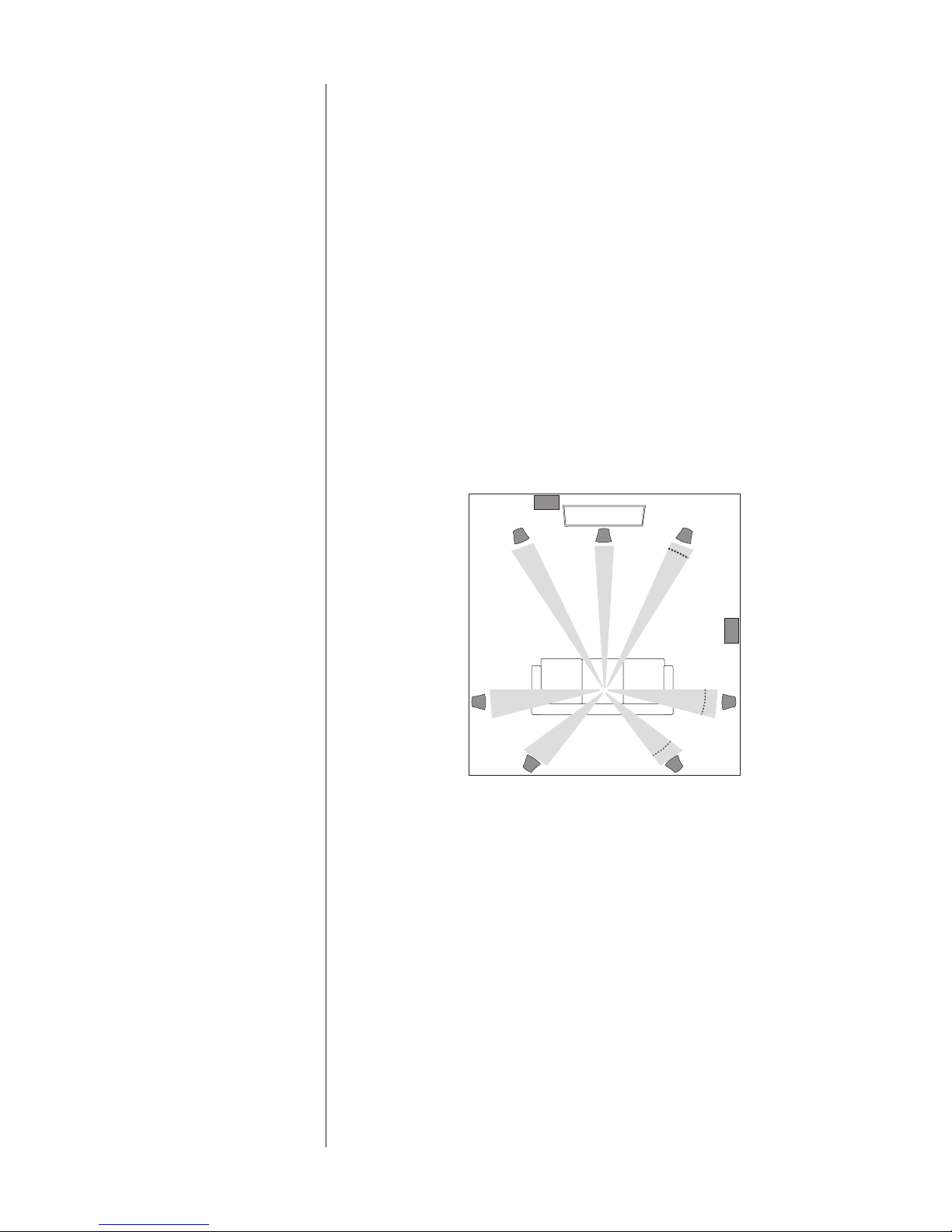
Room Treatment Rectangular rooms have six reecting surfaces (four walls, ceiling and oor)
that reect sound to the listener, after various delays introduced by the indirect
routes the sound take on their way. These rst reections are particularly dam-
aging to sound quality. Looking at the simplest case of stereo reproduction, you
have a minimum of twelve rst reection points in your room that deserve some
attention.
Unfortunately, it is often difcult to do much about the ceiling and oor reec-
tions, even though they are arguably the most destructive. (The minimization of
these reections is one of the strongest arguments for the tall, line source loud-
speakers that Wisdom Audio builds.) This leaves you with eight “rst reections”
that you should consider minimizing somehow. These points are easily found by
having an assistant slide a small mirror along the four walls of the room, while
you sit at the listening position. Any place on the wall where you can see a re-
ection of any speaker is a rst reection point. Concentrate on the rst reec-
tions for the Left and Right speakers rst.
If you can, arrange to apply either absorption or diffusion at these eight points
(don’t forget the wall behind you). Absorption can be as simple as heavy, insu-
lated drapes; diffusion can be provided by a well-stocked bookcase with books
of varied sizes. Alternatively, you can buy purpose-designed room treatments
(some sources listed under References, below).
The important things to remember are these: a good room should have a bal-
ance of absorption and diffusion; and if you are going to treat only a few areas
of the room, the rst reection points are the most important ones to treat.
Professional Acoustic Design Does this all sound too complicated? For good reason: it is complicated.
The difference between the average listening room and one that is professionally
designed and implemented is huge. A great listening room will disappear to an
astonishing degree, letting the experiences captured in your recordings speak to
you directly. A well-designed room is also quieter and more comfortable. It can
easily become a favorite retreat for peace and rejuvenation.
If you decide to investigate the possibility of improving your room with the help
of a professional, it is important to nd someone who focuses on residential
spaces. Most acousticians are trained to deal with large spaces — airports, au-

11
ditoriums, lobbies in commercial buildings, etc. The problems seen in “small”
rooms (residential spaces) are quite different, and outside the experience of most
acousticians. Find someone who specializes in and has a great deal of experi-
ence designing home studios, home theaters, and the like. Your Wisdom Audio
dealer may be such a person; failing that, he/she can help you nd such a pro-
fessional.
References Books on Acoustics:
The Master Handbook of Acoustics, F. Alton Everest, TAB Books
Sound Reproduction: The Acoustics and Psychoacoustics of Loudspeakers and
Rooms by Dr. Floyd Toole, Focal Press
Suppliers of Acoustic Treatments:
Acoustic Innovations, http://www.acousticinnovations.com/
Acoustic Sciences Corporation, http://www.acousticsciences.com/
Echo Busters, http://www.echobusters.com
MSR Acoustics, http://www.msr-inc.com/home_theater/hometheater.html
RPG Diffusor Systems, http://www.rpginc.com/

12
Installing the S55i in a Wall
Your dealer has extensive knowledge of wall construction, and will customize
these installation instructions to suit the needs of your particular situation. These
these notes simply provide an overview of the process.
Note that the Regenerative Transmission Line opening that vents the low fre-
quencies into the room may be placed either up near the ceiling, or down
near the oor. In most rooms, these are largely equivalent positions in terms
of acoustics. The difference will usually be aesthetic rather than performance-
based.
The front board of the S55i is 5⁄8” thick, and presents a smooth, paintable nish
surface similar to dry wall. It can be butted up against the 5⁄8” dry wall, taped,
and spackled, and painted like any other section of wall. It will also readily
accept skim-coating if the construction calls for plaster walls.
The process of installing the S55i in a standard stud wall is quite straightforward.
1. Open the 2 x 4 stud bay to be used
The existing dry wall (if any) should be cut back so it covers about half of
the 2 x 4 on each side of the bay. The ange of the front board of the S55i
will cover the other half.
Obviously, there cannot be any plumbing or wiring in this area of the stud
bay, nor rebreaks. The S55i will use a bit more than half of the available
space in a standard eight foot 2 x 4 stud bay.
2. Stand the S55i in front of the bay in which it will reside; make the elec-
trical connections
There are two methods commonly used for making these connections.
If you have access to the adjacent stud bay, drill a hole through the 2 x 4
stud between where the S55i’s feet will be when it is in place, and feed
the pigtail through the hole. You can then make the connection in the
adjacent stud bay, where you will have plenty of room to work. You can
even put the connections inside a J-box for future serviceability if you so
desire.
Alternatively, sometimes it works out easier to bring the connecting wire
through the top plate or sole plate of the same stud bay in which the S55i
is located. If so, the connection can be made in the space between the
feet at the end of the S55i with the pigtail. If the signal is coming through
the attic and the top plate, the S55i will need to be “upside down” with
its feet at the top of the bay. This places the grille high on the wall, which
may be preferred aesthetically (since it can be mistaken as a surround
speaker).
The preferred method for making the electrical connection is to solder the
wires together and then insulate the connection with shrink tubing. If this
is impractical, use appropriately-sized wire nuts and wrap the wire nut

13
connections in black electrical tape to prevent any chance of the connec-
tion vibrating loose.
3. Stand the S55i in the stud bay, dress the wires so that they cannot rattle,
and screw the front board to the studs with drywall screws
The S55i has predrilled, countersunk screw holes so standard #8 dry wall
screws will sit with their heads below the surface, so they can be tapes
and spackled without any trace. A total of twelve (12) dry wall screws are
used.
The S55i should be supported or suspended in a manner that does not
subject it to twisting or torsional forces that would stress the enclosure.
The enclosure should never be forced against an irregular surface. If the
studs are curved or warped in an installation, the installer must insert
shims between the S55 front panel and the stud surfaces to avoid such
stresses, as would be the case for any in-wall loudspeaker.
4. Tape and spackle the seams
Note that there is a slight recess around the front edge of the S55i to facili-
ate taping and spackling, yielding a smooth result.
5. After everything has been painted, slice the paint along the edge of the
galvanized steel construction shield. Remove and discard the shield.
It is there simply to protect the inside of the S55i, and particularly the
woofers themselves, from being splattered with paint or contaminated
with construction debris. Once that purpose has been served, it needs to
be removed. A sharp utility knife can be used to break any paint that may
have adhered the cover to the face of the subwoofer.
6. Removethegrillefromitsprotectivesleeveandpositionsoitlaysat
against the rubber magnet and wraps around its edges.
When properly positioned, the grille will be fully supported by the rubber
magent and cannot buzz or rattle.

14
Installing the S55i in the Ceiling
The S55i can also be installed above the ceiling, or under the oor, assuming
you have suitable attic or crawl space access. Although the S55i can t between
standard ceiling or oor joists, we recommend placing the S55i across the joists.
It does not have to be perfectly perpendicular to the joists, but should rest
above (or below) them rather than in between them. This prevents its weight
from being supported by the nished surface of the ceiling (dry-wall, plaster,
etc.).
The S55i should be supported or suspended in a manner that does not subject
it to twisting or torsional forces that would stress the enclosure. No wooden or
metal enclosure should be forced against an irregular surface. If the studs are
appreciably curved or warped in an installation, the installer must insert shims
between the S55i front panel and the stud surfaces to avoid such stresses, as
would be the case for any in-wall loudspeaker.
All the following photos are illustrative of how the speakers would be installed
in an attic space, venting into the room below. (Installing it in the oor is similar,
although you might want to replace the HVAC grille with a grate specically de-
signed for oor registers.) Note that while the photos are of the Wisdom Audio
S90i, the process is the same for the S55i.
1. Check your hardware kit to ensure it is complete.
The parts required for in-ceiling mounting include:
• Ceiling ange assembly
• S55i ange assembly
• Two band clamps
• HVAC grille (which optionally can be replaced with one that
matches the other grilles used in the home)

15
• The “Bass Snorkel” (an airtight, rigid, expanding tube that
bridges the gap between the S55i and the ceiling)
• Protecto Wrap for wrapping the Bass Snorkel after it has been
adjusted to the nal length and shape
• #8 dry-wall screws
2. Placetheceilingangeassemblyintheintendedmountinglocation,and
use it as a template for marking the vent into the room. Cut the drywall
with a keyhole saw or similar tool.
3. Screwtheceilingangeinitslocation.

16
4. AligntheS55iangeplateontheS55i,ushwiththecorneroftheen-
closure, and screw into place.
Take care to ensure that there are no air leaks around the edges of the
ange assembly. You want all the low frequency energy transferred
through the “snorkel” into the room.

17
5. Placetheexpandingaluminum“snorkel”ontheceilingangeandcinch
it in place using one of the band clamps.
The snorkel expands over a fairly wide range. It should be lengthened until
is it slightly taller than is needed for the joists in your installation. If your
attic has joists that are smaller than 2” x 8”, you may need to trim the alu-
minum to a more suitable length using a utility knife.
Caution! Be certain that the snorkel can be compressed somewhat before
proceeding to the next step. Once it is fully compressed, any further
pressure placed on it will be transferred directly to the ceiling.

18
6. MovetheS55iintoplaceabovethesnorkel,andgentlyplaceitsange
into the snorkel.
Test t the S55i assembly to the snorkel and ceiling ange. The snorkel
should extend to the back edge of both anges.

19
7. InstallthesecondbandclampontheS55iange.
The next step is to wrap the snorkel in the heavy Protecto Wrap, which dramati-
cally deadens and stiffens the snorkel, and minimizes any leakage of bass into
the attic and adjacent spaces.

20
8. Depending on your access to the work space, either wrap the snorkel in
Protecto Wrap in place, or loosen one of the band clamps and wrap it
in a more convenient position, being careful not to change the length of
the snorkel in the process.
This is a critical step, as it locks the duct into its nal position, greatly
stiffening the assembly and ensuring that the bass energy is vented into
the room rather than leaked into adjacent attic space. Once the snorkel is
wrapped, it is no longer capable to being adjusted for length.
Other manuals for S55i
1
Table of contents
Other Wisdom Subwoofer manuals

Wisdom
Wisdom S90-f/c User manual

Wisdom
Wisdom Sage SCS User manual

Wisdom
Wisdom S10 User manual

Wisdom
Wisdom SCS-2 User manual

Wisdom
Wisdom Sage STS User manual

Wisdom
Wisdom Sage S90i User manual

Wisdom
Wisdom Sage S90i User manual

Wisdom
Wisdom Audio SAS Subwoofer User manual

Wisdom
Wisdom S55i User manual

Wisdom
Wisdom S10P User manual
Popular Subwoofer manuals by other brands

Origin Acoustics
Origin Acoustics SUBV10 installation manual

Ikon
Ikon BB10 instruction manual

Cerasonar
Cerasonar Sub Series installation instructions

AudioEngine
AudioEngine S8 Setup guide

Electro-Voice
Electro-Voice 12" Subwoofer System EVID 12.1. Technical specifications

Definitive Technology
Definitive Technology SuperCube 2000 owner's manual