Streamer 1
Stream Analyzer green 100 % ready, red = busy
Input
Transportstream: green signal: transport stream signal OK.
Transportstream: red signal: transport stream signal error.
Output
Stream: summary of selected streams 1...32 max. or ALL
refer to chapter Streamer 1 - ALL
IP Address: Target IP address (Multicast/Unicast). Output at GbE connector.
Port: Set port number > 1024 ...<49151. (For more informations refer
to Wikipedia, Search: port numbers).
Streaming This field displays all elementary streams in the transport stream.
Select streams by clicking the relevant selection boxes.
E.g. ZDF 28006
- All componets of the stream are then set active.
Disable Output: Disables the selected stream output incl. all components
e.g. Stream 1
Streamer Mode: SPTS = Single Program TransportStream. Selection of severall TS.
Transmodulator: Offers the compact total streaming. refer to chapter
„Streamer 1 Transmodulator mode“
Save: Save settings. Save button inactive when no settings are done.
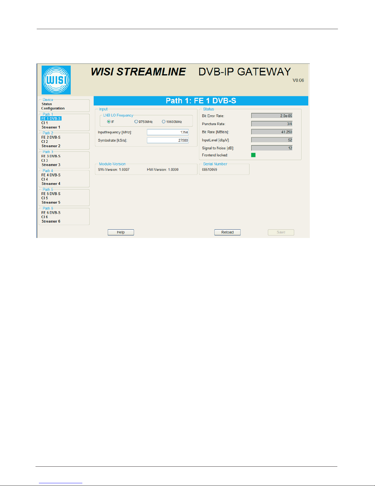
Fig. 1