WiSilica WiseMesh Quick guide

FCC_Configuration Procedures for iOS App

COPYRIGHTCopyright © 2015 WiSilica, Inc. All Rights Reserved. FCC ID: 2AG4NWB10PE
No part of this publication may be reproduced, transmitted, transcribed, stored in a retrieval system,
or translated into any language in any form or by any means without the written permission of
WiSilica, Inc.
TRADEMARKS
WiSeHome, WiSe, WiSe Mesh, WiSe Tech, WiSeApp, WiDe, WiBe, WiSe Connect are
trademarks of WiSilica, Inc. and/or its affiliates in the US and/or other countries. WiSilica Green in
connection with IOT is distinctive of WiSilica brand products. All other registered and unregistered
trademarks herein are the sole property of their respective owners.
LICENSE INFORMATION
License Agreement

WiSeConnect Linkit Bridge Technical Specification
General Information
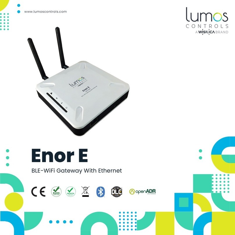
The WiseMesh BLE to WiFi Gatewaty (GW) is a fully integrated GW that provides Internet
connectivity to the WiseMesh BLE esh network. These GWs can be sea lessly integrated with any
enterprise WLAN deploy ent or Ethernet LAN, providing the connectivity to all of the co ponents
within the WiSeMesh network, including: eners, repeeaters,tags and other devices enabled through
the WiSilica BLE odules.
Multiple WiseMesh GWs can be installed within a WiSeMesh network deploy ent and the nu ber
of GWs is deter ined by the application. As an exa ple, a large scale Real-ti e location services
application will require ore GWs and internet capacity than a s all scale connected lighting
application.
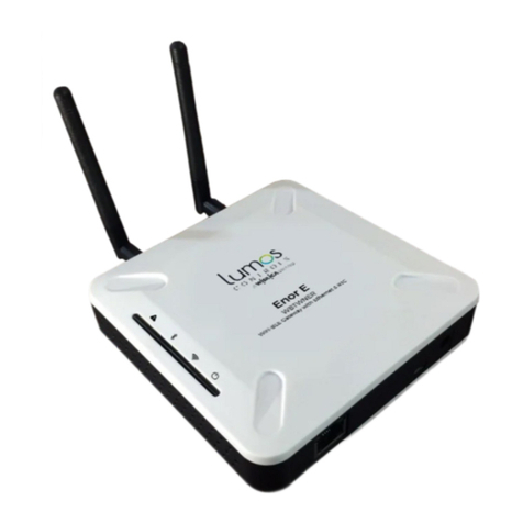
Figure 1 WiFi-BLE Linkit Bridge
Key Features
Power upply Options
The WiSeMesh BLE/WiFi GW supports both Power over the Ethernet (PoE) and Mini USB power
options for flexibility and ease of installation.
Dual Communication and ecurity
Each WiSeMesh BLE/WiFi GW can send and receive data in real ti e fro the BLE connected devices
within the esh to and fro the WiSilica cloud. Each WiSeMesh BLE/WiFi GW is AES 128k encrypted
for device and network security.
WiFi Configuration
The WiseMesh BLE/WiFi GW is configured through a obile application based user interface for WiFi
configuration.
within the WiSeMesh network, including:s th, eners, repewithin the WiSeMesh network,including:listener, repe

WiSeConnect Linkit Bridge Technical Specification
pecifications
Radio Frequency
(BLE 4.0) 2.4-2.48 Ghz
Wireless Standard Supported
WiFi (IEEE 802.11 11b/g) Bluetooth 4.1 Stack WiFI Data Rate up to 72.2 Mbps
WiFi ecurity
WAP-2
Device ecurity
AES 128k Encrypted,
With 3 Level Pairing Keys (Network, App, GUID)
Integrated Antenna
Integrated Antenna,
WiFi – 18dB
BLE- 2.4GHz ~ 2.5GHz 2dBi
External Antenna
O ni Directional Antenna 2 x 50 oh s SMA connectors:
1/2 wave whip
WiFi BLE
Power
Mini USB or PoE (48Vdc)
Physical interfaces
Mini USB, Ethernet with PoE (RJ485)
Dimensions
129 X 130 X 46
Operating Conditions
Te p 0-50°c
WiFi – 14dB
(The device must be professionally installed)

Table of Contents
Table of Contents............................................................................................................................ 3
Table of figures ............................................................................................................................... 4
1Home screen.............................................................................................................................. 5
2Sign up ..................................................................................................................................... 5
3Sign In ...................................................................................................................................... 6
4Organization management ........................................................................................................... 6
5User Management ...................................................................................................................... 8
6Device Commissioning ............................................................................................................. 11
7How to enable listener............................................................................................................... 15
8Bridge Commissioning.............................................................................................................. 16
8.1 Bridge Commissioning via Wi-Fi ........................................................................................ 16
8.2 Bridge Commissioning via Ethernet ................................................................................ 18
8.3 Bridge Commissioning via P.O.E........................................................................................ 18
9How to run Bridge Diagnostics .................................................................................................. 18

Table of figures
Figure 1 Sign Up............................................................................................................................. 5
Figure 2 Sign In .............................................................................................................................. 6
Figure 3 My Organizations .............................................................................................................. 6
Figure 4 Click "Create (+) "option.................................................................................................... 7
Figure 5 Success message............................................................................................................. 7
Figure 6 Users ................................................................................................................................ 8
Figure 7 Click "Create (+) " option................................................................................................... 8
Figure 8 Select User role ................................................................................................................ 9
Figure 9Enter user details ............................................................................................................... 9
Figure 10 Select organization ....................................................................................................... 10
Figure 11 Review the details......................................................................................................... 10
Figure 12 Success message......................................................................................................... 11
Figure 13 "Add device" option ....................................................................................................... 11
Figure 14 Select organization ....................................................................................................... 12
Figure 15 Set a filter...................................................................................................................... 12
Figure 16 Scan for devices ........................................................................................................... 13
Figure 17 Scanned device ............................................................................................................ 13
Figure 18Pair the beacon tag ........................................................................................................ 14
Figure 19 Pair the listener ............................................................................................................. 14
Figure 20 Paired device in dashboard........................................................................................... 15
Figure 21 Listener Enable ............................................................................................................. 15
Figure 22 Scan bridge device........................................................................................................ 16
Figure 23 Pair bridge device ......................................................................................................... 17
Figure 24 Bridge device under default group................................................................................. 17
Figure 25 Bridge commissioning via ethernet................................................................................ 18
Figure 26 Status check ................................................................................................................. 19
Figure 27 Bridge diagnostics......................................................................................................... 19

Overview
WiSe IOT Platform provides end to end user experience providing plug and play hardware for
devices and bridges, and software modules for devices, bridges, apps and cloud. Manufactures,
integrators, distributors, data scientists, application developers, executive management and end
users can directly benefit from deploying and/or integrating with one or more components of the
WiSe platform. WiSe IOT platform combines its innovative WiSe Mesh technology with plug and
play modules to get a devices networked in minutes without any additional hardware. This
document addresses the architecture of WiSe Platform and its components.
Hardware Versions Used
Sl#
Device
Firmware
1
Wise Beacon
1.3.27
2
Wise Mesh Listener
1.3.72
3
Wise Bridge Device
2.1.19
1Home screen
When the application is launched, user will be welcomed by a screen containing four buttons.
1. Forgot Password
2. Sign In
3. Sign Up
4. Skip Sign In
2Sign up
a) Click “Sign Up” button in home screen
b) Enter valid information in all the fields.
c) Click “Sign Up”
On a successful sign up, a new account is created.
Figure 1 Sign Up

3Sign In
a) Enter valid credentials i.e username and password.
b) Click “Sign In”
Figure 2 Sign In
4Organization management
a) Select “My Organizations” option under “Settings” tab.
Figure 3 My Organizations

b) Click on “Create (+)” option.
Figure 4 Click "Create (+) "option
c) Enter organization name and click “Finish”
Figure 5 Success message

5User Management
a) Select “Users” option under “Settings” tab.
Figure 6 Users
b) Click on “Create (+) ” option.
Figure 7 Click "Create (+) " option

c) Select User role and click on “Next” button.
Figure 8 Select User role
d) Enter user details and click “Next” button.
Figure 9Enter user details

e) Select organizations to manage.
Figure 10 Select organization
f) Review the entered details and click on “Finish”.
Figure 11 Review the details

g) Click on “OK” button to complete user creation.
Figure 12 Success message
6Device Commissioning
Device Commissioning is the process of scanning and assigning devices to the groups.
a) Click on “(+)” and select “Add Device” from the main menu options.
Figure 13 "Add device" option

b) Select the organization under which the device is to be commissioned.
Figure 14 Select organization
c) Click on filter icon if the user wants to filter out a particular type of device that needs to be
scanned for in the presence of multiple device types.(OPTIONAL)
Figure 15 Set a filter

d) Click on “Scan”
Figure 16 Scan for devices
e) When the Wise Beacon appears on scanned list, swipe leftwards.
Figure 17 Scanned device

f) Click on “Pair” button .
Figure 18Pair the beacon tag
g) Scan for Wise Mesh Listener and pair the device in a similar manner.
Figure 19 Pair the listener

h) Paired devices will appear in the dashboard.
Figure 20 Paired device in dashboard
7How to enable listener
Click on optional menu in the right end of the paired listener.
Select “Listener Enable”
Figure 21 Listener Enable

8Bridge Commissioning
Creating a bridge user prior to commissioning a bridge device is mandatory. Please refer
heading number 5, “USER CREATION” to create a bridge user and then proceed as follows.
Bridge device has to be commissioned to perform a remote operation.
8.1 Bridge Commissioning via Wi-Fi
a) In order to pair a bridge device, follow steps 6(a) to (d).
Figure 22 Scan bridge device
b) Enter the credentials as follows:
Check the option, Bridge Listener Enabled.
Select the encryption type.
Enter SSID and password.
Place the cursor in the username field and select a bridge user from the list of created
bridge users.
Enter password of the selected bridge user.
Click on “Pair” to get the device paired.

Figure 23 Pair bridge device
c) Paired bridge can be seen in the dashboard under default group.
Figure 24 Bridge device under default group

8.2 Bridge Commissioning via Ethernet
Check the options , Bridge Listener Enabled and Enable Ethernet connection.
Place the cursor in the username field and select a bridge user from the list of created bridge
users.
Enter password of the selected bridge user.
Figure 25 Bridge commissioning via Ethernet
8.3 Bridge Commissioning via P.O.E
Note : The procedure is same as in 7.2. The only difference is that the power is provided to the
bridge via Ethernet cable and hence we need not connect the power cable.
9How to run Bridge Diagnostics
Bridge diagnostics can be used to know the present operational condition of the bridge device.
a) Select optional menu in the right end of bridge name and select “Status check”.
Table of contents
Other WiSilica Gateway manuals
Popular Gateway manuals by other brands

Time Warner Cable
Time Warner Cable CG814W Quick installation guide

Lucent Technologies
Lucent Technologies PacketStar PSAX 4500 user guide

MVC-Data
MVC-Data AccessZone GC1000 Series installation manual

Atrie
Atrie DB120-WL user manual

Pulse Secure
Pulse Secure MAG2600 Hardware guide

M-system
M-system WL40EW2F instruction manual