WITA SM WR FR User manual

ONLY ORIGINAL WITH THE DIAMOND®
|www.wita.de |
WITA Fixed Setpoint Controller SM WR FR
INSTALLATIONSHANDBUCH
FESTWERTREGLER SEITE 2–18
INSTALLATION GUIDE SETPOINT
VALUE CONTROLLER PAGE 20–36
INSTALLATIONSHANDBUCH
FESTWERTREGLER STRONA 38–54
D
GB
PL

Operating instrutions
WITA Fixed Setpoint Controller SM WR FR
Table of Contents
Declaration of conformity ........................................................................................................
Safety instructions.....................................................................................................................
General........................................................................................................................................................
Instructions of symbols in the operating instructions...................................................................
Personnel qualification...........................................................................................................................
Dangers of not observance of the safety instructions..................................................................
Safety conscious working......................................................................................................................
Safety instructions for the operator...................................................................................................
Safety instructions for installation and maintenance....................................................................
Unauthorized conversion and spare parts production .................................................................
Unpermitted operation ..........................................................................................................................
Transport and storage ............................................................................................................
Intended Use ..............................................................................................................................
Technical data for the WITA fixed value controller..............................................................
Dimensions ..............................................................................................................................................
Technical specifications .........................................................................................................................
Operating elements of the fixed value controller SM WR FR.....................................................
Graphic Display ........................................................................................................................................
User guide..................................................................................................................................................
Ads in case of failure...............................................................................................................................
Manual mode.............................................................................................................................................
Assembly of the controller SM WR FR on heating mixer.....................................................
Mounting of the fixed setpoint controller SM WR FR onto dierent mixing valves ............
Electrical installation...............................................................................................................................
Safety instructions before and for commissioning ...............................................................
For visible damage..................................................................................................................................
Selection and setting of the applications setting temperature and mixer (valve)
direction of rotation................................................................................................................................
- Selection of application heating .....................................................................................................
- Selection and adjustment of the set point temperature ..............................................................
- Selection and adjustment of the mixer (valve) direction of rotation .......................................
Selection of hydraulic scheme and setting the minimum setpoint and maximum
temperature...............................................................................................................................................
- Selection of hydraulic scheme .............................................................................................................
- Selection and adjustment of the minimum maximum and setpoint temperature
for the heating application....................................................................................................................
- Selection and setting of the minimum maximum and setpoint temperature during
application cooling ..................................................................................................................................
Commissioning of the WITA fixed setpoint controller SM WR FR......................................
Sensor features ..........................................................................................................................
Sensor resistance values........................................................................................................................
20

Display HE Pumpen
Operating instrutions
WITA Fixed Setpoint Controller SM WR FR
21
EC Declaration of Conformity
Name of the issuer: WITA-Wilhelm Taake GmbH
Pumpen-, Armaturen- und Regeltechnik
Böllingshöfen 85
D-32549 Bad Oeynhausen
Subject of the declaration: Fixed Setpoint Controller
Type: SM WR FR
Design: SM W FR
SM W FR
We declare with sole responsibility that the products specified above, to which this
EC Declaration of Conformity refers, fulfil the following standards and guidelines:
Electromagnetic Compatibility Directive 2014/30/EU
EN 55014-1 : 2006 + A1 : 2009 + A2 : 2011
EN 55014-2 : 1997 + A1 : 2001 + A2 : 2008
EN 61000-3-2 : 2014
EN 61000-3-3 : 2013
Low Voltage Guideline 2014/35/EU
EN 60730-1:2017-05
EN 60730-2-14 : 2009-06
EN 60335-1 : A11:2014
RoHS-Richtlinie
RoHS 2011/65/EU
EN 63000:2019-05
This declaration is submitted for and on behalf of the manufacturer by:
Bad Oeynhausen, 06.12.2019
Frank Kerstan
Management

Operating instrutions
WITA Fixed Setpoint Controller SM WR FR
2 Safety Instructions
2.1 General
These installation and operating instructions are a part of the
product, and contain basic information that must be observed
during installation, operation and maintenance. For this reason,
the installer and specialist personnel or operators must read
these instructions prior to set-up.
Please observe both the general safety instructions listed
under section 2 and the special safety instructions detailed in
the other sections.
A copy of the EC Declaration of Conformity is provided with
these instructions. This declaration shall be deemed void in the
event of a modification that has not been agreed with us.
2.2 Identification of notes in the operating instructions
General hazard symbol
Warning! Danger of personal injury!
Observe the relevant accident
prevention regulations.
Warning! Danger from electrical vol-
tage! Prevent hazards arising from
electrical energy. Observe the instructi-
ons in local or general regulations (e.g.
IEC, VDE, etc.), and those of the local
energy supplier.
22

Operating instrutions
WITA Fixed Setpoint Controller SM WR FR
This symbol indicates useful information
for handling the product. It indicates
potential diculties and aims to ensure
safe operation.
Signs attached directly on the product, such as:
• direction of rotation arrow
• type plate
• identification of connections must be strictly observed and
kept in an easily legible state.
2.3 Personnel qualification
The personnel used for mounting, operation and maintenance
must have relevant qualifications. Areas of responsibility
and monitoring of personnel must be guaranteed by the
owner/operator. If personnel do not have the necessary
know-how, they must be trained or instructed accordingly.
This device can be used by children at or above the age of 8
years, as well as by persons with reduced physical, sensory or
mental capabilities, or who lack experience and knowledge, if
they are supervised or have been instructed concerning the safe
use of the device and if they understand the hazards arising
from its use. Children may not play with the device.
Cleaning and maintenance operations may not be carried out
by children without supervision.
23
Note

Operating instrutions
WITA Fixed Setpoint Controller SM WR FR
2.4 Danger of not observing safety instructions
Not observing the safety information can endanger persons,
the environment and the system. Not observing the safety
instructions shall result in the loss of any and all claims to
warranty.
Potential dangers include:
• Hazards to persons through electrical and mechanical eects.
• Failure of important system functions.
• Hazard to the environment from escaping fluids resulting
from a leak.
• Failure of prescribed repair and maintenance work.
2.5 Safety-conscious working
Observe the safety instructions detailed in this manual, along
with the current national accident prevention regulations.
Should the system operator also have their own internal regu-
lations, these must also be observed.
2.6 Safety instructions for the operator
• Any existing touch guard protecting moving parts may be
neither removed nor shut down while the system is in opera-
tion.
• In the event of a fluid leak, any fluids must be collected or di-
verted in a way that prevents hazards to persons and the en-
vironment from arising.
• Prevent hazards arising from electrical energy.
24

Display HE Pumpen
Operating instrutions
WITA Fixed Setpoint Controller SM WR FR
• Observe the instructions in local or general
regulations (e.g. IEC, VDE, etc.), and those of the
local energy supplier.
• In the event of hazards arising from the system due to
contact with hot or cold parts, these parts must be fitted
with a touch guard.
• Keep flammable substances away from the product.
2.7 Safety instructions for installation and maintenance work
The system operator is responsible for ensuring that all instal-
lation and maintenance work is carried out by qualified per-
sonnel. These persons must also have familiarised themselves
in advance with the product using the operating instructions.
Conducting work on the pump is only permitted when the sys-
tem is shut down.
Ensure that the device is securely disconnected from the
power supply. Disconnect the device plug to achieve this.
Prescribed instructions for shutting down the device can be
found in the operating instructions. All protective mechanisms,
such as a touch guard, must be correctly reattached after
work.
2.8 Unauthorised conversion and production of spare parts
Modification or conversion of the product is only permitted
after prior consultation with the manufacturer. Only use origi-
nal spare parts for repairs. Only use accessories that have been
approved by the manufacturer. The manufacturer shall bear no
25

Operating instrutions
WITA Fixed Setpoint Controller SM WR FR
liability for any consequences resulting from the use of other
parts.
2.9 Unpermitted operation
If the pump is disconnected from the power supply, wait at
least 1 minute before reactivating. Otherwise, the pump's in-
rush current limit has no eect, which can lead to functional
errors or damage to any connected heating controller.
The pump's operational safety can only be ensured if it is used
as intended. Please observe section 4 of these
operating instructions here. Ensure compliance with
the limit values detailed in the technical data.
3 Transport and Storage
After receiving the product, inspect it immediately for damage caused in transport.
Should you detect any transport damage, assert a claim with the haulier.
Incorrect transport and storage can lead to personal injury or damage to the product.
• Protect the product against frost, moisture and damage during transport
and storage.
• Only carry the pump by the pump housing, and never by the connection
cable or terminal box.
• If the packaging weakens due to moisture, this can lead to the pump falling out
and causing severe injury.
26

Display HE Pumpen
Operating instrutions
WITA Fixed Setpoint Controller SM WR FR
4 Intended Use
The WITA fixed setpoint controller SM WR FR is a constant or fixed setpoint
temperature controller for heating or cooling systems. His field of application is,
the return flow, the control of surface heating, or where constant temperatures
are needed.
5 Technical data for the WITA fixed setpoint controller
5.1 Dimensions
5.2 Technical specifications
SM WR 5FR SM WR 10FR
torque 5 Nm 10 Nm
Rotation angle 90 °
Rotation Speed 2 min / 90°
Operating mode 3-Point, PDI
Supply voltage 230 VAC , 50Hz
Power consumption max. 5W
Power consumption
during standby max. 0,5W
Temperature range 0 -50 °C
Protection I to EN 60730 -1
Protection class IP 42 to EN60529
Dimensions (w x l x h) 95x80x92 mm
Weight ca. 900 g
27

Operating instrutions
WITA Fixed Setpoint Controller SM WR FR
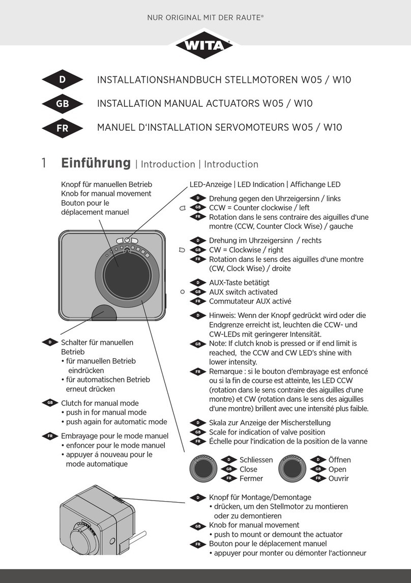
5.3 Operating elements of the fixed value controller SM WR FR
1. Graphic display
2. Button (Help / User Guide).
3. Button for manual operation.
4. Removable button for manual
operation.
5. Button (return)
6. Button (Go to the left
or increase in value)
7. Button (Go to the right
or increase in value)
8. Button )
9. USB connection for PC
Pressing selection buttons (2) or setting buttons (5, 6, 7, and 8) is carried out when
pressed an acoustic signal.
5.4 Graphic display
The base of the display of the fixed setpoint controller are
• the operating mode
• the actual and target temperature
• if necessary, also the hydraulic diagram displayed with symbols and current values.
Displayed symbols:
Heating
Cooling
Valve direction of rotation counterclockwise
Valve direction of rotation clockwise
Return temperature
Flow temperature
Transmission defect
Target temperature
Error
28
Operating mode
Measured temperature
Requested temperature
Operating mode
Measured- and requested
temperature
Hydraulic scheme
2 3 4 5 6 7 8 91

Display HE Pumpen
Operating instrutions
WITA Fixed Setpoint Controller SM WR FR
5.5 User Guide Button (2) Help / User Guide
It serves as information for the operation
of the settings for
• set temperature adjustment
• Selection heating / cooling
5.6 Ads in case of failure
29
see point
7.2-2
see point
7.2-1
Basic display
Basic display Basic display

Operating instrutions
WITA Fixed Setpoint Controller SM WR FR
5.7 Manual mode
In the event of a fault, the fixed setpoint controller has the option of being switched from
automatic mode to manual mode, so that emergency operation is possible.
6 MAssembly of the controller SM WR FR
on heating mixer
6.1 Mounting the fixed setpoint controller SM WR FR to dierent mixers can only be made
with manufacturer-specific mounting kits.
When selecting the drive, please observe because of the torque the data sheet of the
mixer while mounting with manufacturer-specific mounting kits, the enclosed installation
instructions has to be observed!
The drive is equipped with a special mounting
flange. By pressing the assembly / disassembly
button, a simple, tool-free installation of the fixed-
value controller on the mixer or the valve or disas-
sembly is possible.
30
Note
Adjustment knob (4) for manual operation
Button (3) for manual operation
• Press manual operation
• Press again for automatic operation.
If the button is pressed for manual
operation, it will be shown graphically
in the display! Basic display
Einbaulage des Reglers Die Anzeige des
Displays passt sich stets der Einbaulage
des Festwertreglers auf dem Mischer an
Scale for displaying
the mixer position
close open
close open
Example !
Note

Display HE Pumpen
Operating instrutions
WITA Fixed Setpoint Controller SM WR FR
6.2 Electrical installation
Due to the preassembled main connection cable and the preassembled
temperature sensor the SM WR FR is immediately ready for operation.
The temperature sensor was installed for flow temperature control at the flow line of the
heating or cooling circuit. For the return temperature control the sensor is installed at the
return of the boiler.
7 Safety instructions before and for commissioning
7.1 In the case of visible damage of the package or the product is it not to use.
The installation of a damaged product can be life threatening!
Observe the correct opening direction of the mixer or valve for controller
settings. Turning directions can carry out to high or too low temperatures in the system.
Minimum and maximum setpoint temperatures must be set correctly. Incorrect selected li-
mits may cause undesired temperature settings and – consequently - unwanted operation
which may damage the system. Every system, in which the controller is integrated, must
have independent system protection for too low or too high temperatures.
The controller has no protection function if the temperature in the system are too low or
too high.
7.2 Selection and setting of the applications, set temperature and mixer (valve) direction of
rotation.
The selection of the settings "application", "setting temperature" or "direction of rotation"
can be preset or carried out during commissioning.
7.2.1 Selection of the heating or cooling application
After confirming, the controller continues working with the changed setting!
31
Note
Basic display Heating Cooling
The setting will be done
by the the buttons
+ or -
selected and confirmed
with key.

Operating instrutions
WITA Fixed Setpoint Controller SM WR FR
7.2.2 Selection and setting of the set point temperature
The adjustment can be done by the but-
tons and .
1 ° increments and confirmed with the
key . The change will be immediately
shown in the display and the controller
works with the new setting.
7.2.3 Selection and adjustment of the mixer (valve) direction of rotation
The setting can be
adjusted with the
and keys
and confirmed
with the key
7.3 Selection of hydraulic scheme and setting of minimum, setting and maximum temperature
The selection for the settings of the "hydraulic diagram" and the "min. and max. Tempera-
tures" can only be made during commissioning in the mode Controller commissioning..
7.3.1 Selection of hydraulic scheme
32
Basic display
Basic display
1. Return temperature
Return tem-
perature
control
Open
clockwise
Open counter
clockwise
2. Flow control
Flow tem-
perature
control
and

Operating instrutions
WITA Fixed Setpoint Controller SM WR FR
7.3.2 Selection and adjustment of the minimum, maximum and set point
temperatures for the application
Heat.
Setting range of temperatures
for min. temperature =
10 ° - 70 ° setting temperature =
min. temp. --- max. temp.
max. temperature =
set point + 5 ° - 90 °
The setting range for the value of the minimum temperature is = 10 ° to 70 °, the setting range
for the value of the maximum temperature is the setting temperature plus 5 ° to 90 °. For the
setting temperature value, the range is selectable between the minimum-temperature-maxi-
mum temperatures. The possible setting range is shown in the respective display in the
lower scale.
Factory setting when heating as flow control
Minimum - temperature 20 °, maximum - temperature 40 °, nominal temperature 30 °
Factory setting for heating as return high maintenance
Minimum - temperature 50 °, maximum - temperature 70 °, setting temperature 60!
The settings for cooling mode are not processed in heating mode!
33
min.
temperature
max.
temperature
setting
temperature

WITA Fixed Setpoint Controller SM WR FR
34
Operating instrutions
7.3.3 Selection and adjustment of the minimum, maximum and set point temperatures for
the application
Cool.
Setting range of temperatures
for min. temperature = 5 ° - 30 °
setting temperature =
min. temp. --- max. temp.
max. temperature =
set point 10 ° - 40 °
The setting range for the value of the minimum temperature is = 5 ° - to 70 °, the setting range
for the value of the maximum temperature is the setting temperature plus 10 ° to -40 °. For the
setting temperature value, the range is selectable between the minimum-temperature-maxi-
mum temperatures. The possible setting range is shown in the respective display in the
lower scale.
Factory setting when cooling as flow control
Minimum - temperature 5 °, maximum - temperature 40 °, nominal temperature 24 °
Factory setting for cooling as return high maintenance
Minimum - temperature 16 °, maximum - temperature 40 °, setting temperature 60!
The settings for cooling mode are not processed in heating mode!
Min. Soll-
Temperatur
Max. Soll-
Temperatur
setting
temperature

WITA Fixed Setpoint Controller SM WR FR
35
Operating instrutions
8 Commissioning of the WITA Fixed Setpoint
Controller SM WR FR
When the controller is connected to the mains for the first time, the display shows the type of
the controller, the program version and the LOGO are displayed.
The display then changes to the base display. The base display shows at the first Commissioning
the factory setting, then the last set values and the Settings.
To make new settings with the controller the hand adjustment knob must be disassembled, so
that the adjustment buttons are accessible.
By simultaneously pressing the buttons (5s).
If the display changes to selection mode, it can be adapted to the existing system (see proce-
dure)
Mit Confirmation of the display will save the settings.
Basic display
Cooling Open clockwise
Flow control
selection
heating / cooling
max. temperature
heating
min. temperature
heating
selection valve
direction of rotation
selection
hydraulic scheme
setting tempe-
rature heating

WITA Fixed Setpoint Controller SM WR FR
36
Operating instrutions
9 Sensor
The temperature sensor is preassembled on the fixed setpoint value controller
with flow temperature control, it is installed on the flow line of the heating
circuit. In the return temperature control on the boiler return.
The recommended installation location is 0.5 m behind the heating pump. Clean
the heating pipe well during installation Apply thermal grease and temperature
sensor, alternatively the temperature sensor can also be used as an immersion
sensor
9.1 Sensor resistance values.
Note
Temperature Resistance Temperature Resistance Temperature Resistance Temperature Resistance
[°C] [W] [°C] [W] [°C] [W] [°C] [W]
-20 922 35 1136 90 1347 145 1555
-15 941 40 1155 95 1366 150 1573
-10 961 45 1175 100 1385 155 1592
-5 980 50 1194 105 1404 160 1611
0 1000 55 1213 110 1423 165 1629
5 1020 60 1232 115 1442 170 1648
10 1039 65 1252 120 1461 175 1666
15 1058 70 1271 125 1480 180 1685
20 1078 75 1290 130 1498 185 1703
25 1097 80 1309 135 1415 190 1722
30 1117 85 1328 140 1536 195 1740

Notes
37

ONLY ORIGINAL WITH THE DIAMOND®
WITA - Wilhelm Taake GmbH
Böllingshöfen 85 | D-32549 Bad Oeynhausen
Tel.: +49 5734 512380 | Fax: +49 5734 1752
HEL-WITA Sp. z o.o.
Zielonka, ul. Biznesowa 22 | 86-005 Białe Błota
Tel.: + 52 564 09 00 | Fax: + 52 564 09 22
www.hel-wita.com.pl | biuro@hel-wita.com
Stand 10/2019 · Produktionsbedingte Abweichungen in Maßen und Ausführungen behalten wir uns vor.
Irrtum und technische Änderungen vorbehalten.
This manual suits for next models
2
Table of contents
Other WITA Controllers manuals