Witschi ANALYZER Q1 User manual

ANALYZER Q1
INSTRUCTION MANUAL
Please read before you work with the device!

Page 2 Analyzer Q1 Witschi Electronic Ltd
Witschi Electronic Ltd.
Bahnhofstrasse 26
3294 Büren an der Aare
Switzerland
Phone: +41 (0)32 - 352 05 00
Fax: +41 (0)32 - 351 32 92
Internet: www.witschi.com
E-Mail: [email protected]
Original Manual
Document No. 26.6410D35e
Rel. 1.2
Last modification: August 2017

Witschi Electronic Ltd Analyzer Q1 Page 3
TABLE OF CONTENTS
1GETTING STARTED..................................................................................................................................5
2FIELD OF APPLICATION...........................................................................................................................5
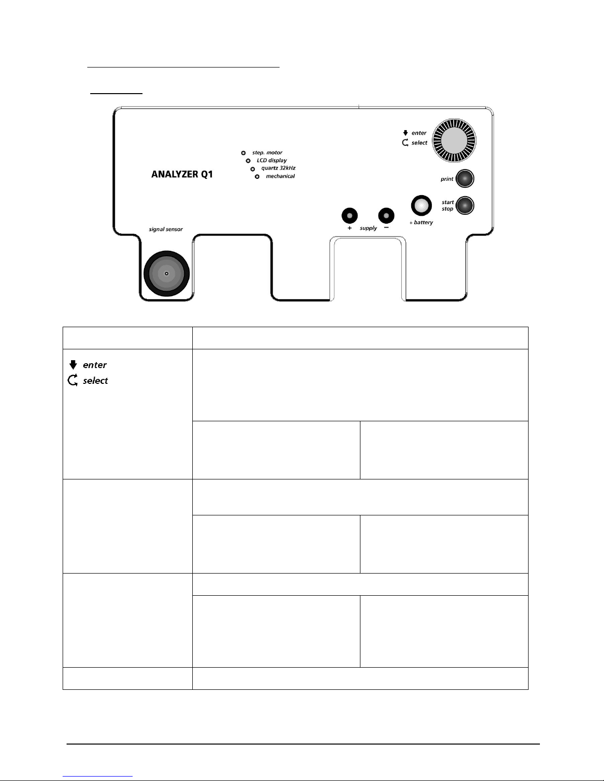
3OPERATING ELEMENTS AND DISPLAYS...................................................................................................6
3.1 Work Area .............................................................................................................................................. 6
3.2 Rear panel .............................................................................................................................................. 7
3.3 Display Panel.......................................................................................................................................... 8
4COMMISSIONING ...................................................................................................................................8
4.1 Extent of Delivery ................................................................................................................................... 8
4.2 Place of Installation................................................................................................................................ 9
4.3 Mains Connection................................................................................................................................... 9
4.4 Printer Connection.................................................................................................................................. 9
4.5 Language................................................................................................................................................ 9
5GENERAL OPERATION ..........................................................................................................................10
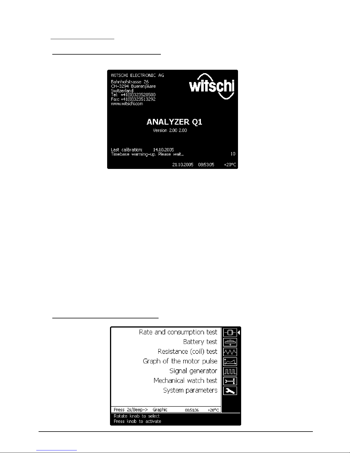
5.1 Switching the Analyzer Q1 On and Off................................................................................................. 10
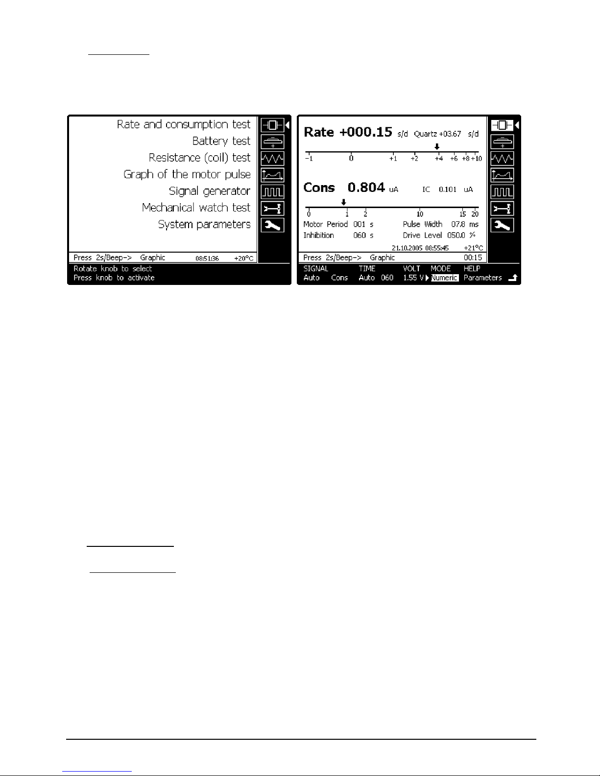
5.2 Selection of a Measurement Function .................................................................................................. 10
5.3 Parameter Settings ............................................................................................................................... 11
5.4 Help...................................................................................................................................................... 12
6RATE MEASUREMENT OF QUARTZ WATCHES .......................................................................................13
6.1 General Introduction ............................................................................................................................ 13
6.2 Measurement Sequence ....................................................................................................................... 13
6.3 Result Display....................................................................................................................................... 14
7PULSE PARAMETERS.............................................................................................................................15
7.1 General Introduction ............................................................................................................................ 15
7.2 Result Display....................................................................................................................................... 15
8LONG-TIME RECORDING (TRACE MODE) ..............................................................................................15
8.1 Result Display....................................................................................................................................... 15
9MODULE SUPPLY AND CURRENT MEASUREMENT.................................................................................16
9.1 Connecting the Watch .......................................................................................................................... 16
9.2 Current Measurement........................................................................................................................... 17
9.3 Minimum Operating Voltage................................................................................................................ 18
9.4 Watch Acceleration .............................................................................................................................. 19
10 BATTERY TESTING ................................................................................................................................19
10.1 Connecting Points ................................................................................................................................ 19
10.2 Test Sequence....................................................................................................................................... 19
10.3 Result Display....................................................................................................................................... 20
11 GRAPH OF THE MOTOR PULSE..............................................................................................................20
11.1 General Introduction ............................................................................................................................ 20
11.2 Procedure ............................................................................................................................................. 20
11.3 Result Display....................................................................................................................................... 21
12 TEST OF COIL RESISTANCE AND COIL INSULATION ...............................................................................21
12.1 General Introduction ............................................................................................................................ 21
12.2 Procedure ............................................................................................................................................. 21
12.3 Result Display....................................................................................................................................... 22
13 TEST OF STEP MOTORS WITH THE SIGNAL GENERATOR ........................................................................22
13.1 Field of Application .............................................................................................................................. 22
13.2 Procedure ............................................................................................................................................. 22

Page 4 Analyzer Q1 Witschi Electronic Ltd
14 BUZZER TEST........................................................................................................................................23
14.1 Field of Application .............................................................................................................................. 23
14.2 Procedure ............................................................................................................................................. 23
15 TESTING MECHANICAL WATCHES ........................................................................................................24
15.1 General Introduction ............................................................................................................................ 24
15.2 Procedure ............................................................................................................................................. 24
15.3 Result Display....................................................................................................................................... 24
15.4 Long-Time Recording............................................................................................................................ 25
16 ADDITIONAL TECHNICAL INFORMATION ..............................................................................................25
16.1 Signal Sources for Rate Measurement.................................................................................................. 25
16.2 Watches with Inhibition Compensation................................................................................................ 28
16.3 Influence of the Temperature ............................................................................................................... 28
16.4 Typical Values of the Rate Deviation.................................................................................................... 28
16.5 Motor Pulse Analysis............................................................................................................................ 29
16.6 End Of Life (EOL) Function.................................................................................................................... 30
16.7 Battery Testing ..................................................................................................................................... 31
17 SYSTEM PARAMETERS..........................................................................................................................32
17.1 Procedure ............................................................................................................................................. 32
17.2 TYPE General........................................................................................................................................ 32
17.3 TYPE Interfaces PRINTER...................................................................................................................... 34
17.4 TYPE Info.............................................................................................................................................. 35
18 CONNECTION TO A PC .........................................................................................................................36
18.1 Field of Application .............................................................................................................................. 36
18.2 Installation ........................................................................................................................................... 36
19 MAINTENANCE ....................................................................................................................................36
20 TECHNICAL DATA.................................................................................................................................36
20.1 Measurement Functions ....................................................................................................................... 36
20.2 Additional Functions ............................................................................................................................ 39
20.3 Options................................................................................................................................................. 39
20.4 General Data ........................................................................................................................................ 39
21 ACCESSORIES.......................................................................................................................................40

Witschi Electronic Ltd Analyzer Q1 Page 5
Congratulations!
You made the right choice.
You bought ANALYZER Q1, an extremely accurate test instrument, technically reliable as well as
easy to handle and operate.
Follow the given instructions regarding usage and maintenance and you will enjoy this new
instrument for quite a long time. It will be a pleasure and will prove profitable for you to use this
device.
1GETTING STARTED
Please read carefully all the information contained in this manual.
Strictly follow the operating instructions, which will help you to use
and safely operate our product. Keep this manual in a safe place near
the instrument and give it to any other user.
The facility must be used only for the aims and purposes described in this very manual and must be
set up and operated as described and under the conditions herein specified.
The Manufacturer, Witschi Electronic AG in CH-3294 BÜREN a.A., SWITZERLAND takes no
responsibility and offers no warranty for damages that may follow from the non-observance of
these directives or from inappropriate handling, such as damages to the checking device, to
watches and/or people.
2FIELD OF APPLICATION
ANALYZER Q1 is the perfect test instrument to be used quickly and efficiently in the repair service, in
the sales department and the watch-testing lab.
A new technology provides extended test and measurement facilities, allowing a professional
troubleshooting of quartz watches. Largely automated measuring cycles provided by the instrument
result in an unmatched user-friendliness.

Page 6 Analyzer Q1 Witschi Electronic Ltd
3OPERATING ELEMENTS AND DISPLAYS
3.1 Work Area
Operating Elements
signal sensor
Signal transducer for capacitive, magnetic and acoustic signals.
Rotary knob for selecting measuring functions and setting up
parameters.
It has a twofold function: functions, parameters or information are
selected by rotating the knob and activated by pressing it.
Short pressure on the knob
Activates the selected function or
parameter settings.
Long pressure on the knob
Back to main menu
print
Key for printing the measurement log or transferring measurements to
a PC.
Short pressure on the key
Current results printed as a
measurement log
Long pressure on the key
Screen contents printed as a
graphic image
start/stop
Key for starting and stopping a measurement.
Short pressure on the key
The current measurement is
stopped and immediately
restarted.
Long pressure on the key
The measurement is stopped until
it is restarted by shortly pressing
the key.
+ battery
+ battery support for the battery test.

Witschi Electronic Ltd Analyzer Q1 Page 7
LED Displays
step. motor
Signal level of the motor pulses, signal acquisition magnetic or
through the supply current.
LCD display
Signal level of the LCD signal (capacitive).
quartz 32kHz
Level of the 32 kHz quartz signal (acoustic, capacitive or through the
supply current).
mechanical
Signal level of the watch noise (acoustic).
Connections
+ battery
+ battery support for the battery test.
+ supply -
Connections for the direct supply of modules or watch movements
with two movable contact probes.
3.2 Rear panel
Rear panel
I O
Main switch for switching the system on / off.
module supply –+
Connections for test probes for testing batteries and motor coils
(supply of modules and movements is not possible).
power 9V~ 1.2A
Connection socket for mains adapter, either 230 V~ or 120 V~.
PC
RS232 interface with a PC
printer
RS232 interface for log printer
calibration
RS232 interface for Witschi’s GPS receiver.
sensor
Connection socket for external signal transducers.
microph.
Connection socket for external microphone (only available with
Analyzer Twin).

Page 8 Analyzer Q1 Witschi Electronic Ltd
3.3 Display Panel
The display panel, which can be tilted to the best viewing angle, is equipped with a lighted ¼ VGA
LCD graphic screen (320x240 dots).
Main menu Rate and consumption test menu
The display is divided into several fields
The right-hand bar contains the symbols for the miscellaneous measurement functions. The
selected function has a white background and is indicated by a white arrow .
The parameters and information belonging to the selected function are displayed on the
lower horizontal bar and can be selected there. The selected parameter has a white
background and blinks.
The current numerical and graphical results are displayed on a white background in the result
field.
This field also contains information or parameters depending on the selected function.
An information line under the result field contains information on the current measurement
4COMMISSIONING
4.1 Extent of Delivery
The basic equipment comprises the following components:
Test instrument ANALYZER Q1.
Mains adapter 230 V~ or 120 V~.
2 cables with probe tips.
Pair of movable contact probes.
Movement holder.
Dust-proof cover.
Instruction manual.

Witschi Electronic Ltd Analyzer Q1 Page 9
4.2 Place of Installation
Signal acquisition can be disturbed by electrical and magnetic stray
fields from electrical equipment. Computer terminals, fluorescent
lamps and ultrasonic cleaning equipment cause especially strong
interferences. It is therefore necessary to place the equipment far
enough from such interference sources. The influence of interfering
electromagnetic radiations may prevent the instrument of
functioning flawlessly.
4.3 Mains Connection
A mains adapter supplies ANALYZER Q1 with a 9 V~ output alternating voltage and a 1.2 A output
current. The mains adapter can be provided for a 230 V~ mains voltage (from 210 V~ to 240 V~) or
a 120 V~ mains voltage (from 110 V~ to 130 V~).
Before connecting for the first time, make sure that the voltage of the
mains adapter corresponds to the voltage of your mains.
Only use the original Witschi mains adapter!
Connect the mains adapter to the appropriate socket on the rear panel of the instrument.
We recommend disconnecting the mains adapter from the mains during longer idle periods, e.g.
vacations.
4.4 Printer Connection
Connect the printer available as an accessory, to the
printer
connector. The connecting cable is
delivered together with the printer.
Caution! Before connecting the printer, make sure that the voltage of its power supply
corresponds to the voltage of your mains.
4.5 Language
If the preset language or other system parameters do not correspond to your requirements, you can
modify them in the
System parameters
menu (see chapter 17.2)

Page 10 Analyzer Q1 Witschi Electronic Ltd
5GENERAL OPERATION
5.1 Switching the Analyzer Q1 On and Off
The mains switch for switching the instrument on and off is located on its rear panel.
Whenever the instrument has been switched on, the following information appears during the
stabilisation period of the time base: Name and address of the manufacturer, instrument type,
firmware version, date of last calibration, time and date, as well as ambient temperature (if
temperature display switched on).
The instrument jumps to the main menu and is ready to function at the end of the stabilisation
period (20 s).
If no measurement is performed for a long time (can be set in
System parameters
menu), the
instrument automatically switches to standby mode in which the display lighting is switched off. The
consumption of < 2 W in standby mode is negligible.
The instrument can be “woken up” from the standby mode by pressing any key.
We recommend only switching off the instrument during longer idle periods. Switching often the
instrument on and off influences the stability of the time base.
Shouldn’t you need to use the device for an extended period (e.g. vacations), it is recommended to
disconnect the mains adapter from the mains.
5.2 Selection of a Measurement Function

Witschi Electronic Ltd Analyzer Q1 Page 11
Automatic Selection
In automatic test mode (selected in
System parameters
menu) the measurement functions
Rate and
consumption test,
Battery test
and
Mechanical watch test
are automatically selected as soon as the
instrument receives an exploitable watch signal. In this way, the measurements that are most often
carried out can be performed without accessing the instrument at all.
If the signal is no longer available, the measurement function that has been automatically selected
remains active for a few seconds before the instrument jumps back to the main menu.
Manual Selection
The measurement functions
Resistance (coil) test, Graph of the motor pulse
and
Signal generator
must be manually selected.
The other functions that can be automatically selected can also be manually selected (e.g. for batch
testing).
A manually selected function remains active until a jump back to the main menu has occurred (also
when no signal is available).
Place the arrow (on the right-hand side of the display) on the desired function by rotating the
knob. Then press the rotary knob for activating the function.
When a function has been selected, the cursor jumps to the parameter line of the selected
measurement function.
To return to the main menu, place the cursor on the
Back
arrow by rotating the knob, and then
press it. You can also keep the rotary knob pressed until the instrument jumps directly to the main
menu.
5.3 Parameter Settings
The cursor jumps to the parameter line after a function has been activated. The parameters differ
according to the function.
After a measurement function has been selected, all parameters are set to the most commonly
preferred values. Modified parameters are reset to the preferred values when the measurement
function is exited.

Page 12 Analyzer Q1 Witschi Electronic Ltd
Die Parameters
SIGNAL
and
TIME
can be automatically selected by the instrument; they are
identified with the label
Auto
and the current automatically determined value. The automatic
selection can be overridden by a manual selection.
A manual selection must only be used when measurements is to be carried out with a deliberately
chosen value different from the automatically determined value.
Procedure
Use the rotary knob to select the parameter to be set. The current parameter setting will appear
on a rhythmically blinking white background.
Press the rotary knob.
A white arrow appears on the left of the parameter setting.
Use the rotary knob to select the desired parameter setting.
Finally, press the rotary knob to confirm the setting.
You can then select other parameters to carry out other setting operations.
Please note: Some parameters
react immediately to any change (without confirmation by pressing
the rotary knob). This can be used for instance for modifying the module supply voltage.
Back to Main Menu
Use the rotary knob to select arrow .Pressing the rotary knob sends you back to the main
menu.
Alternatively, keep the rotary knob pressed for approx. 2 seconds. A short beep confirms the
return to the main menu. The position of the cursor does not play any role in this case.
5.4 Help
The
HELP
parameter caption allows retrieving information about parameter selection or the
interpretation of measurement results.
Select parameter
HELP
and press the rotary knob.
Select
Parameters
or
Results
according to the information desired.
Press the rotary knob once more to go back to measurement.

Witschi Electronic Ltd Analyzer Q1 Page 13
6RATE MEASUREMENT OF QUARTZ WATCHES
6.1 General Introduction
Signal Acquisition
The Analyzer Q1 is equipped with a single transducer for acoustic, capacitive and magnetic signal
acquisition. It allows checking watches with closed wristlet, open watches and movements.
If the watch is supplied from the Analyzer Q1, its rate deviation is derived from the supply current
(see chapter 9.2).
When the
SIGNAL
parameter is set to
Auto
, the instrument automatically selects the suitable signal
source according to the watch signal. You can also select manually another signal source.
Caution Due to the danger of faulty measurements in the case of watches with inhibition
compensation, this signal source
Quartz
is not selected automatically. To perform a
rate measurement through the quartz frequency, it is necessary to select manually the
Quartz
signal source with the
SIGNAL
parameter.
Additional information about the selection of the signal source is available in chapter 16.1
Measurement time
The measurement time for analogue watches must correspond to a pulse period of the stepping
motor or to a multiple thereof. Watches with inhibition compensation must be tested over an
inhibition period or a multiple thereof.
When the
TIME
parameter is set to
Auto,
the rate is first measured with the shortest possible
measurement time. If the rate deviation exceeds ± 0.5 s/d, the instrument “assumes” it is dealing
with an inhibition compensation watch. The measurement time is automatically set to 60s, a value
that matches most of the watches with inhibition compensation. If a shorter or longer inhibition
period is detected during measurement (e.g. 10 s or 120 s), the measurement time is modified
accordingly. Additional information about inhibition watches is available in chapter 16.2
The measurement time can be manually selected for special measurements.
6.2 Measurement Sequence
The watch is placed on the transducer and can be shifted to some extent if necessary until the signal
LED lights up strongly or blinks.
LCD watches must be positioned on the signal transducer with the dial face downward.
Measurement starts automatically from the main menu as soon as an exploitable signal is detected.
The instrument jumps to test mode
Rate and consumption test.
The suitable signal source (magnetic motor pulse, current pulse or LCD display frequency) is
automatically selected. The measurement time needed for measurement is also automatically
determined. It is only necessary to set up the instrument if measurement is to be deliberately carried
out with parameters other than those automatically selected (see chapter 17.2).

Page 14 Analyzer Q1 Witschi Electronic Ltd
The information line displays the indication
check
until the instrument has determined the
measurement parameters.
As soon as the measurement proper starts, the indication
Run
appears on the information line and a
countdown counter indicates the remaining measurement time. The start of the measurement
process is also audibly signalled.
The result is displayed once the measurement time has elapsed. The measurement is continuously
performed as long as an exploitable signal is available. In the case of longer measurement times,
result updates are audibly signalled.
A running measurement can be interrupted and restarted by briefly pressing the
start/stop
key.
If the watch signal lies outside of the measurement range (± 325 s/d) or is so distorted that an
evaluation is not possible, the message
out of range
or
unstable
appears on the information line.
If the signal is no longer available, the indication
No Signal
appears and the instrument jumps to the
main menu after a while.
Caution! If a watch is supplied from the Analyzer Q1, it is not possible to test another watch
with the sensor.
6.3 Result Display
In
Numeric
mode, the current results are displayed in numerical and graphical analogue form.
The actual rate deviation is displayed with large size characters in the upper left-hand part of the
result field at the end of the measurement time.
The deviation of the quartz frequency is also displayed for informational purpose with smaller
characters in the upper right-hand part of the result field. (In the case of watches with inhibition
compensation, the deviation of the quartz frequency does not correspond to the actual rate
deviation).
The instantaneous rate deviation also appears in graphical form on a logarithmic scale. The
instantaneous value is always measured with the shortest possible measurement time (2 s in most
cases), irrespective of the selected measurement time.
Additional results from pulse analysis that are displayed in the case of analogue watches are
described in chapter 7.

Witschi Electronic Ltd Analyzer Q1 Page 15
7PULSE PARAMETERS
7.1 General Introduction
In the case of the rate measurement based on the magnetic or current stepping motor pulses, the
instrument also analyzes the motor pulses. This analysis provides valuable information on the
operation of the watch module. In particular, the present power level of watches with adaptive motor
pulses (Asservissement) can be determined without opening the watch (see chapter 16.5).
7.2 Result Display
The following pulse parameters are measured and displayed:
Motor period and display of the
End of Life
function.
Inhibition (see chapter 16.2)
Pulse Width
Drive Level (percentage of the chopping level, see chapter 16.5).
The chopping level is also graphically represented as a bar diagram.
8LONG-TIME RECORDING (TRACE MODE)
When the
MODE
parameter is set to
Trace
, a long-time recording of the rate deviation and of the
chopping level is performed as a diagram.
Long-time recording includes changes in the rate deviation (e.g. caused by temperature variations)
as well as changes in the chopping level of watches with adaptive motor pulses (e.g. caused by a
change of date) for a duration reaching 60h.
8.1 Result Display
The upper part of the display contains the rate measurement diagram and the lower part the power
level of the chopping pulses.

Page 16 Analyzer Q1 Witschi Electronic Ltd
Time Scale
One point is recorded for each measurement; the recording length is equal to 240 points. The time
scale is therefore determined by the selected measurement time. In our example, the diagram has
been recorded for 4 hours (1 point per minute).
Exiting the Trace Mode
To avoid inadvertently deleting the results of a long-time recording, the instrument does not return
automatically from the
Trace
mode to the main menu when the signal is not available any longer. It
is necessary to leave the
Trace
mode by manually selecting another mode or by manually returning
to the main menu.
9MODULE SUPPLY AND CURRENT MEASUREMENT
9.1 Connecting the Watch
Caution! The watch can be damaged if the power is fed to the wrong locations or with the wrong
polarity.
It is necessary to remove the battery from the watch to measure the consumption and the lowest
start voltage.
To connect the watch or the movement, it is clamped into the module holder and laid onto the glass
surface of the instrument. The movable contact probes with telescopic probes are put onto the
connection points of the watch and pressed down to such an extent that they are retracted by
approximately 1 mm. To adjust the height, catch hold of the rear end of the contact probes.
Place the red +probe onto a point known to be connected to the +terminal of the battery (battery
case). The entire plate of most watches is connected to the +terminal.
Place the black –probe onto a point known to be connected to the –terminal of the battery (battery
cover). In most watches, the contact spring is the most accessible point connected to the –battery
terminal.
To avoid interferences, the measurement cables connected to the rear part of the instrument do not
belong to the measuring path of the current and cannot be used to measure currents.
If a watch is too big or if its wristlet is closed, so that the probes cannot be used for establishing the
contact, the measurement cables can be used instead of the probes by connecting them to the base
plate. Since the probe tips are held with the hand during measurement, the resulting interferences
may impair the stability of the measurement results.
If the contacts are performed correctly, the
quartz 32kHz
LED lights up and the
step motor
LED blinks
to the rhythm of the step motor.
The mirror underneath the support allows you to watch the hands of the watch. If the watch is running,
the contacts have been correctly set up.
The consumption and rate measurement starts automatically from the main menu as soon as the
instrument detects a current.

Witschi Electronic Ltd Analyzer Q1 Page 17
9.2 Current Measurement
9.2.1 General Introduction
The current consumption of a quartz watch constitutes an important quality criterion and indicates
the expected lifetime of the battery.
The current of analogue quartz watches is composed of the IC current and of the current spikes
associated with motor pulses. The instrument IC captures the value of the IC current as well as the
value of the overall average current during the measurement time (integrating measurement).
9.2.2 Selection of the Supply Voltage
For performing current and rate measurements through the supply current, select the nominal
voltage according to the battery type.
The nominal voltage of the most widely used silver oxide batteries is equal to 1.55 V. This value is
automatically selected when the measurement function is started.
Most of the less frequently used lithium batteries have a nominal voltage of 3 V.
When the
VOLT
parameter is selected, the supply power can be adjusted with the rotary knob in the
range from 0 to 3.5 V.
9.2.3 Functionality of the “variable Trigger”
Applicable for the rate- and current measurement over the motor pulses b external power supply of the
watch.
Especially for thermo-compensated quartz watches or quartz movements with measuring times of 480
and 960 seconds.
An accurate rate- and current measurement with external power supply over the magnetic pulse
requires a trouble-free motor pulse signal (
Menu Motor
).The variable trigger (
spike
filter) should
ignore/filter out interfering inhibition signals.This is mainly the case for quartz watches with
temperature compensation (measuring time 480 / 960 seconds).
Analyzer Q1/Twin controls the
spike
filter function by a variable supply voltage of 1.55V to 3.50V
Graphical representation of the trigger (spike-filter) operation:
Supply
Voltage
Spike -
filtering
X µA
=>1.75V - 3.50V
125 µA
1.70V
102 µA
1.65V
77 µA
1.60V
52 µA
1.55V
27 µA

Page 18 Analyzer Q1 Witschi Electronic Ltd
9.2.4 Measurement Time
The measurement time for correctly determining the average consumption of analogue watches
must correspond to a pulse period of the stepping motor or to a multiple thereof.
When the
TIME
parameter is set to
Auto
, the measurements are performed automatically over 2
pulse periods and, in the case of watches with pulse period >5 s, over a single pulse period.
Another measurement time can be selected manually for carrying out special measurements. The
manually selected measurement time is identical for the rate and consumption measurements.
The IC current is always measured during a 2 s measurement time.
The IC current of LCD watches is the total current.
Please note: The first result for the total current of LCD watches only appears after 35 s.
9.2.5 Result Display
The results for the current are only displayed when a current is flowing; they are masked when there
isn’t any current flowing.
The total current and the IC current are displayed separately.
In addition, the instantaneous consumption appears in graphical form on a logarithmic scale. The
instantaneous value is always measured with a 2 s measurement time (value in IT2s), irrespective of
the selected measurement time.
The rate deviation is measured at the same time as the current measurement and the pulse
parameters are analyzed (see chapter 7).
Typical values
The manufacturer data are binding as regards the maximal admissible consumption of the watch.
The typical current consumption of a modern analogue quartz watch with seconds lies
approximately between 0.8 and 1.2 µA and approximately between 0.5 and 0.7 µA for watches with
a longer pulse period (without seconds).
9.3 Minimum Operating Voltage
The minimum operating voltage supplies information on the power reserve of the watch and its
capability to function even with a nearly exhausted or strongly stressed battery. The correct

Witschi Electronic Ltd Analyzer Q1 Page 19
operation of the
End Of Life
(
EOL
) function can also be tested by decreasing the voltage (see chapter
16.6).
Please note: Various voltage-dependent functions of the watch, such as
Asservissement
or
End of
Life,
react to change in voltage with a delay of up to 4 minutes.
The supplied voltage is decreased by steps, while observing the hands of the watch in the mirror
until the watch stops, and then slowly increased once more until it runs again.
The
VOLT
parameter reacts immediately to any change, i.e. without acknowledgment by pressing
the rotary knob. Pressing the rotary knob is only necessary when exiting from the parameter.
It is usually enough to test the correct operation of the watch with a reduced supply voltage. The
minimum operating voltage of watches with a silver oxide battery is equal to 1.2 V in most cases.
9.4 Watch Acceleration
Many watch modules are equipped with a test point (mostly designated by R/T) accessible on the
electronic module. The acceleration and reset functions can be activated with this test point. This
can be achieved by using the probe tip to establish a contact with the test point in addition to the
supply with contact probes. With most movements, establishing a contact with the +terminal
activates
Reset
(the motor pulses are disabled) while establishing a contact with the –terminal
activates the acceleration.
For additional information, kindly refer to technical information for this particular movement.
In accelerated mode, the watch performs 16 or 32 steps per second. The motion of the hands can be
observed in the mirror and mechanical problems, e.g. due to hands touching or to the change of
date can be identified quickly.
10 BATTERY TESTING
10.1 Connecting Points
Place the +side of the battery to be tested on the contact surface of the
battery
support and establish
the contact with the –side using the black contact probe or the black probe tip.
In most cases, the battery can also be directly tested in the open watch by means of the probe tips.
Pay attention to the polarity of the battery when testing it.
- In the case of a standard silver oxide battery, the case corresponds to the +terminal and the case
cover to the –terminal.
- In the case of batteries for large-sized watches, the case corresponds to the –terminal and the
contact on the case cover to the +terminal.
- Lithium batteries are available in different executions. Check the indications on the battery (+ or –
sign) or the indications from the manufacturer.
10.2 Test Sequence
In automatic test mode, the instrument automatically detects that a battery has been connected
and switches to the
Battery test
mode. The
Battery test
mode can also be selected manually.
The voltage with a minimal load demand (
No Load
) is continuously measured and displayed.
A load of 2 kΩis switched on once per second for 10ms; it simulates the step motor. The voltage
associated to this load (
Low Drain
)
is continuously determined and displayed.

Page 20 Analyzer Q1 Witschi Electronic Ltd
To measure the voltage with a high load demand (
High Drain
), briefly press the start button; this
will switch on the load for 1 s. This load simulates the lighting or alarm function.
The
High Drain
measurement should not be repeated several times since the high load demand
quickly drains the battery.
10.3 Result Display
The voltage without load is displayed in analogue form in addition to the numerical results.
The
High Drain
voltage is only displayed when this measurement has been initialized by pressing the
start button.
Additional information about battery test is available in chapter 16.7.
11 GRAPH OF THE MOTOR PULSE
11.1 General Introduction
The Analyzer Q1 can record the motor current pulse as an oscillogram. In addition to the pulse
parameters, the shape of the current pulse provides additional information on the state of the watch.
In particular, faults can be detected in the mechanical part of the watch by comparing its
measurements to those of a watch of the same type in good condition.
Additional information about motor pulse analysis is available in chapter 16.5.
11.2 Procedure
- Supply the watch with the Analyzer Q1 according to chapter 9.1
- Select the
Graph of the motor pulse
function in the main menu
- The time scale can be selected with the
RANGE
parameter according to the pulse width.
- The measurement is usually performed with the nominal voltage corresponding to the battery
(1.55V for watches with a silver oxide battery). The voltage can be changed with the
VOLT
parameter, e.g. for testing the operation of the watch under reduced supply voltage.
Table of contents
Other Witschi Test Equipment manuals