Metrix OX 832 User manual

Copyright © 906121641 - Ed. 3 - 04/00
OX 832
30 MHz-DIFFERENTIAL
OSCILLOSCOPE
User's manual

30 MHz-differential o cillo cope
2
CONTENTS
1. GENERAL INSTRUCTIONS....................................................................................................... 3
1.1. Safety precaution ................................................................................................................ 3
1.1.1. Before u e ..................................................................................................................... 3
1.1.2. During u e ..................................................................................................................... 3
1.1.3. Symbol ......................................................................................................................... 4
1.1.4. In truction .................................................................................................................... 4
1.2. Guarantee ............................................................................................................................ 4
1.3. Maintenance and metrological verification............................................................................ 4
1.4. Servicing .............................................................................................................................. 4
2. INSTRUMENT DESCRIPTION ................................................................................................... 5
2.1. Front panel de cription......................................................................................................... 7
2.2. Rear panel de cription.......................................................................................................... 8
3. GETTING STARTED .................................................................................................................. 9
3.1. AUTOSET ............................................................................................................................ 9
3.2. Vertical channel ................................................................................................................ 11
3.3. Di play mode .................................................................................................................... 12
3.4. Timeba e ........................................................................................................................... 13
3.5. Trigger................................................................................................................................ 13
3.6. Trigger delay (DELAY) ....................................................................................................... 15
4. APPLICATIONS ....................................................................................................................... 17
4.1. Vi uali ation of the calibration ignal.................................................................................. 17
4.2. Mea urement of amplitude and frequency.......................................................................... 17
5. SPECIFICATIONS.................................................................................................................... 18
5.1. Vertical deflection............................................................................................................... 18
5.2. Horizontal deflection........................................................................................................... 19
5.3. Trigger y tem ................................................................................................................... 19
5.3.1. Trigger delay coefficient............................................................................................... 20
5.4. AUTOSET function............................................................................................................. 20
5.4.1. AUTOSET pecification ............................................................................................. 20
5.5. General characteri tic ....................................................................................................... 21
6. SUPPLIES AND OPTIONS....................................................................................................... 22
6.1. Acce orie ........................................................................................................................ 22
6.1.1. Provided with the apparatu ......................................................................................... 22
6.1.2. Provided a option ..................................................................................................... 22
6.2. Option ............................................................................................................................... 22

30 MHz-differential o cillo cope
3
1. GENERAL INSTRUCTIONS
You have ju t purcha ed a 30 MHz-differential o cillo cope; we congratulate you on your
choice of thi high quality product.
Thi apparatu complie with IEC afety tandard 61010-1 +A1 +A2 (1995) ingle
in ulation, dealing with electronic mea urement in trument . Plea e read the e in truction
carefully and re pect the u age precaution , in order to obtain the be t u e from it.
Failure to re pect warning and / or u age in truction may damage the apparatu and / or
it component and may be dangerou to the u er.
1.1. Safety precautions
1.1.1. Before use
- Thi in trument wa de igned for u e indoor in an environment with a degree of
pollution 2 at an elevation of le than 2000 m, a temperature between 0°C and
40°C, and a relative humidity of 80 % up to 31°C.
- It can be u ed for mea urement on 300 V category III and 600 V CAT II (input )
in tallation and can be upplied by a 253 V CAT III network.
- Definition of in tallation categorie ( ee publication IEC 664-1):
CAT I : CAT I circuit are protected by device limiting tran ient overvoltage to a
low level.
Example: protected electronic circuit
CAT II : CAT II circuit are power upply circuit for dome tic or digital device that
may include tran ient overvoltage with an average value.
Example: power upply for hou ehold appliance and portable tool .
CAT III : CAT III circuit are power upply circuit for power equipment that may
include large tran ient overvoltage .
Example: power upply for indu trial machine or equipment
CAT IV : CAT IV circuit may include very high tran ient overvoltage .
Example: energy arrival
- Depending on the po ition of the fu e on the ba ic board, thi in trument may be
powered by a 110 V
AC
or 230 V
AC
± 10 % network. Before connecting up the
in trument, check that the fu e po ition matche the rated voltage of your
di tribution network. To do thi , remove the top cover from the o cillo cope.
- Earth all metallic part that are acce ible to touch (including the working table).
- You are advi ed to u e the acce orie delivered with the in trument or propo ed
a option . Check that they are in perfect working condition before u e.
- Plug the cable into a ocket fitted with an earth connection.
1.1.2. During use
- Select vertical en itivity and timeba e range adapted to the mea urement.
When carrying out a measurement, never touch an unused terminal of the instrument.
The replacement fuse must be identical to the original fuse.
It is located inside
the apparatus in a housing on the cathode ray tube support part.

30 MHz-differential o cillo cope
4
1.1.3. Symbols
Refer to the u er' manual.
Incorrect u e may re ult in damage
to the device or it component .
Ri k of electric hock
Ground
1.1.4. Instructions
- Before opening the apparatus, alway di connect it from the main power upply
and mea urement circuit , and make ure that you are not charged with tatic
electricity which could damage internal component .
- Any repair, maintenance or adju tment of the o cillo cope when it i powered may
only be done by qualified per onnel, after reading the in truction in thi manual.
- A "qualified person" i a per on who i familiar with the in tallation, con truction
and u e and the danger pre ent. He i authorized to witch the in tallation and
equipment on and off in accordance with the afety rule .
- Take care not to ob truct ventilation hole when u ing the apparatu .
1.2. Guarantee
Thi o cillo cope i guaranteed again t any material defect or manufacturing vice in
accordance with the general condition of ale.
During the guarantee period (2 year ), the apparatu may only be repaired by the
manufac-turer, and the manufacturer will be free to decide to repair or replace all or
part of the apparatu . The guarantee condition tate that the manufacturer will pay
for return tran port.
The guarantee i not applicable in the following ca e :
1. any improper u e of the equipment or if it i u ed in a ociation with incompatible
equipment;
2. modification of the equipment without explicit authorization by the manufacturer’
technical department ;
3. work done by a per on not approved by the manufacturer;
4. adaptation to a pecific application not included in the definition of the equipment
or by the operating in truction ;
5. a hock, drop or flooding.
1.3. Maintenance and metrological verification
Return your in trument to your di tributor for any work to be done within or out ide
the guarantee.
1.4. Servicing
Clean the in trument with a wet cloth and oap. Never u e abra ive product or
olvent .
Some internal capacitors may retain a dangerous potential, even after the apparatus
has been switched off.

30 MHz-differential o cillo cope
5
2. INSTRUMENT DESCRIPTION
Thi in trument i a 30 MHz portable differential o cillo cope with AUTOSET. It
technology ha been de igned to ati fy the mo t demanding u er . It i intended for
electrotechnician and electronic expert (operation in normal or differential mode).
Thi o cillo cope' input can operate in both traditional and differential mode (independent
witching acce ible on the front):
in traditional mode
∗ Input CH1+ and CH2+ are active.
∗ Input CH1- and CH2- are inhibited internally, but the impedance a een from the input
remain con tant.
in differential mode
∗ Input CH1+ CH1- and CH2+ CH2- are active.
∗ The ignal di play corre pond to the difference between the ignal pre ent on
input CH 1+ and CH1- (and/or CH2+ and CH2-).
The voltage common to the inputs (CH1+, CH1-) or (CH +, CH -) is called the
common mode voltage Vcm.
∗ The peak common mode voltage max. Vcm depend on the calibre elected:
• 20 V for en itivitie from 10 mV to 0.5 V
• 200 V for en itivitie from 1 V to 5 V
• 600 V for en itivitie from 10 V to 200 V/div.
Vdiff
Vcm
CH1- CH2-
CH1+ CH2
+
ou
The representation of the signal on the screen may be erroneous when the max.
common mode voltage authorized for the calibre selected is exceeded.
Performance of the oscilloscope
∗ 2 channel at 30 MHz
∗ High input dynamic: 10 mV to 200 V/div. (14 calibre )
∗ Triggering up to 50 MHz
∗ Trigger delay function
∗ The AUTOSET function automatically earche for the vertical en itivity and the
canning coefficient adapted to the ignal pre ent on channel CH1 and CH2.
The front panel i managed by an 8-bit microcontroller with FLASH memory which
handle the following ta k :
∗ Reading of the ab olute en itivity and time ba e coder
∗ Management of the LED
∗ Configuration of the ba ic board by erial link
∗ Management of communication with the PC via the RS232C link with the
HA1255 programming kit (optional)
∗ Generation of the calibration ignal
∗ Saving of the in trument' configuration in EEPROM
6
30 MHz-differential o cillo cope
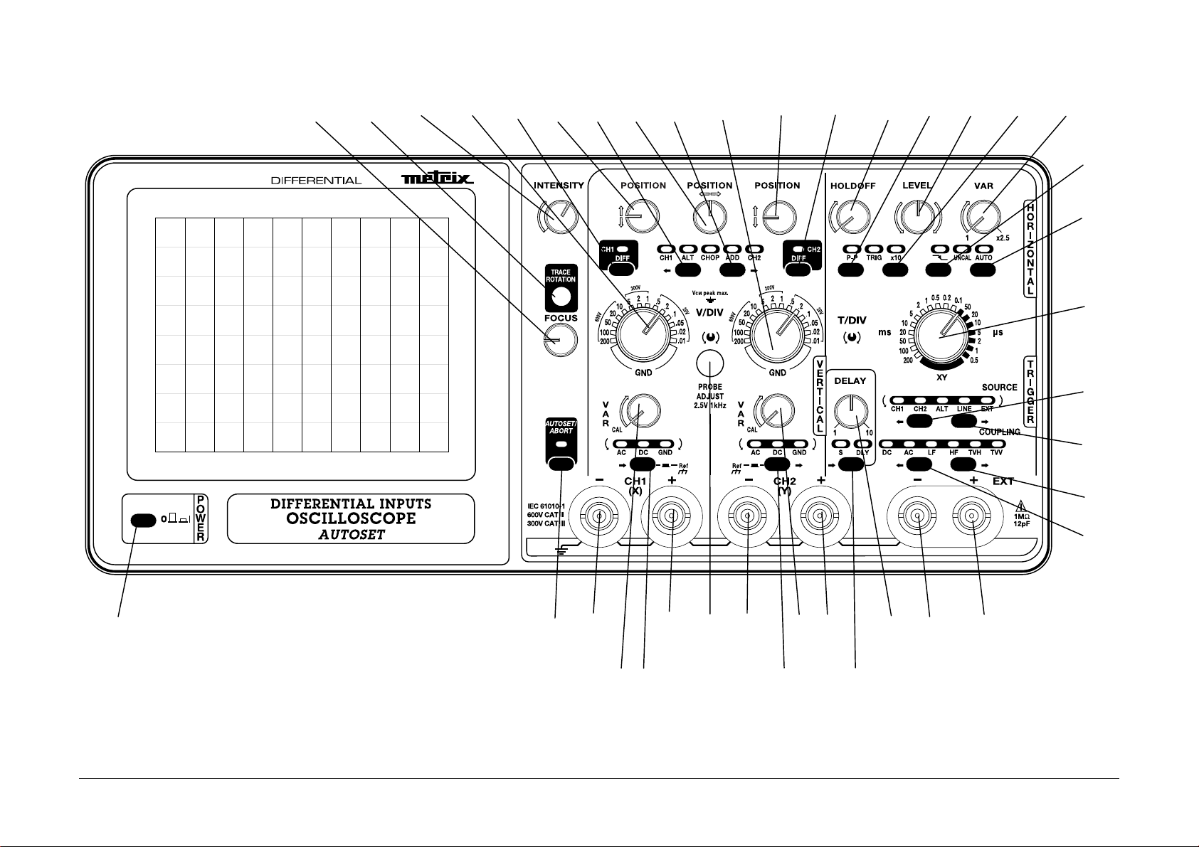
Figur 1 : Fac avant
1 2 3 4 5 6 7 8 9 10 11 12 13 14 15 16 17
39 38 37 34 33 32 30 29 27 26 25
18
19
20
21
22
23
24
36 35 31 28
OX 832
30MHz

30 MHz-differential o cillo cope
7
2.1. Front panel description
1 - FOCUS
•
focu adju tment
- TRACE ROTATION
•
adju tment of the horizontal trace alignment
3 - INTENSITY
•
adju tment of the trace brightne
4 -
VOLT/DIV
•
election of the vertical en itivity for CH1
5 - CH1 DIFF
•
witching to normal or differential operating mode of CH1 channel
6 - POSITION
•
adju tment of the vertical po ition of CH1 trace
7 - MODE
•
right/left croll of vertical mode
8 - POSITION
•
adju tment of the horizontal po ition of CH1 or CH2 trace
9 - MODE
•
left/right croll of vertical mode
10 -
VOLT/DIV
•
election of the vertical en itivity for CH2
11 -
POSITION
•
adju tment of the vertical po ition of CH2 trace
1 -
CH2 DIFF
•
witching to normal or differential operating mode of CH2 channel
13 -
HOLDOFF
•
adju tment of HOLDOFF TIME ( weep holdoff)
14 -
P-P
•
activation of peak-to-peak trigger mode
15 -
LEVEL
•
adju tment of trigger level
16 -
x 10
•
expan ion by 10 of the horizontal weep coefficient
17 -
VAR
•
continuou adju tment of weep coefficient of timeba e
18 -
•
activation of po itive or negative trigger lope
19 -
AUTO
•
activation of AUTO or triggered weep mode
0 -
T/DIV
•
election of the weep coefficient of timeba e
1 -
SOURCE
•
right/left croll of trigger ource
-
SOURCE
•
left/right croll of trigger ource
3 -
COUPLING
•
left/right croll of trigger ource
4 -
COUPLING
•
right/left croll of trigger ource
5 -
EXT +
•
external trigger + input
6 -
EXT -
•
external trigger - input
7 -
DELAY
•
adju tment trigger delay of timeba e
8 -
S / DLY
•
election of SEARCH ou DLY (delayed) weep mode
9 -
CH2 +
•
CH2 channel input
30 -
VAR
•
continuou adju tment of the CH2 vertical en itivity
31 -
COUPLING
•
election of CH2 channel coupling or mea urement on CH2
3 -
CH2 -
•
CH2 channel - input
33 -
PROBE ADJUST
•
calibration output
34 -
CH1 +
•
CH1 channel + input
35 -
COUPLING
•
election of CH1 channel coupling or mea urement on CH1
36 -
VAR
•
continuou adju tment of the CH1 vertical en itivity
37 -
CH1 -
•
CH1 channel - input
38 -
AUTOSET/ABORT
•
activation/deactivation of the AUTOSET function
39 -
POWER
•
ON/OFF key

8
30 MHz-differential o cillo cope
2.2. Rear panel description
42 45 40 41 43 42
44
Figur 2
(40) Location of th optional HA1255 PROGRAMMING KIT conn ctor
Thi RS232C erial link (40) e tabli he the communication between the o cillo cope
and a PC or compatible computer. It enable :
- the remote programming of the o cillo cope
- the reading of the o cillo cope configuration
(41) Mains plug
(42) Cord wind rs
(43) Mains plug location wh n carrying th oscilloscop
(44) Fus lab l
(45) Z Modulation
Input BNC at the back
Sen itivity TTL level
High level on
Low level off
Max. frequency 4 MHz
Input re i tance approx. 2 kΩ
Max. voltage ± 20 V
DC

30 MHz-differential o cillo cope
9
3. GETTING STARTED
Respect the safety instructions indicated in Chapter 1.
- Position the rotary controls as indicated in the figure 1.
- Press the POWER key (39): the last memorised configuration of the front panel is
restored.
- Validate the AUTO key (19).
- Adjust : - brightness with the INTENSITY potentiometer (3),
- the thickness of thetraces with the FOCUS potentiometer (1),
- the horizontalness of the traces with the potentiometer to be reached
through the TRACE ROTATION hole (2).
Adjust the brightness of the trace according to ambient lighting. Excessive
brightness can damage the tube, particularly when there is no sweeping in process
(spot stationary).
- Apply the ignal to be di played to channel CH1 or CH2.
- Pre on the AUTOSET key (3) .
- When u ing a 1/10 probe, u e the PROBE ADJUST ignal (33) (2.5 V, 1 kHz) to adju t
the probe compen ation (refer to § 4. APPLICATIONS).
3.1. AUTOSET
• AUTOSET automatically carrie out the following earche :
active channel, vertical en itivity, horizontal deflection coefficient, trigger lope.
• AUTOSET automatically put the o cillo cope into the following configuration:
ynchro PTP, AC coupling of the connected channel, horizontal magnitude x 1,
DC coupling of the trigger ource.
• AUTOSET doe not affect : POSITION (H and V), VAR, DELAY, INTENSITY.
The AUTOSET function i activated by pre ing the AUTOSET/ABORT key (38) (key only
active while pre ed):
- The AUTOSET/ABORT LED remain on during the earch pha e.
- When the earch pha e end , if the calibre found by the AUTOSET function are
different from tho e indicated by the vertical en itivity and time ba e witche , the
AUTOSET/ABORT LED fla he .
- There are two way of quitting the AUTOSET function:
Manual earch for the range found by AUTOSET:
• You earch for the AUTOSET range by turning the (4) and/or (10) en itivity and
(20) time ba e witche in the direction indicated by the coupling or trigger- ource
LED which i fla hing.
• The AUTOSET LED goe out when all the range determined by the AUTOSET
have been found.
Pre ing the AUTOSET/ABORT key (38) again will cancel the AUTOSET function.
Vertical adjustment is not set by the AUTOSET. You should ensure that position (6)
and (11) rotary controls are correctly centred
10
30 MHz-differential o cillo cope
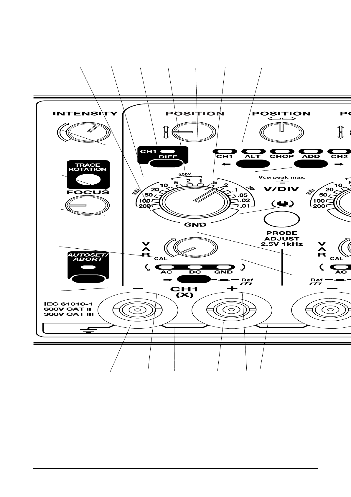
Figure 3
3
2
1
36
38
4 5 6 7 8 9 11
12
10
33
30
37 35 34 32 31 29

30 MHz-differential o cillo cope
11
3.2. Vertical channels
Refer to figure 3.
(6) - (11) POSITION - Vertical centring of the CH1 (6) and CH2 (11) trace .
(8) POSITION - Horizontal centring of the trace .
Thi command act imultaneou ly on CH1 and CH2.
(4) - (10) VOLT/DIV - CH1 (4) and CH2 (10) vertical en itivity :
14 po ition (10 mV to 200 V/div.).
(36) - (30) VAR - Continuou adju tment of CH1 (36) and CH2 (30) vertical en itivity.
When the knob i locked in the left-hand po ition, the corre ponding UNCAL
indicator light i out.
(31) - (35) AC - DC - GND
Selection u ing the (31) key for the CH2 channel and (35) for the CH1 channel :
Vi uali ation of the AC component (deletion of the
AC DC GND
DC component).
Vi uali ation of the full ignal
AC DC GND
Coupling of the channel to earth (without hort-circuiting the
AC DC GND
input ignal). Enable accurate po itioning of the trace on the
creen u ing the POSITION control (6) and (11).
(34) - (37) CH1+ CH1- + and - inputs of signals to be observed on BNC sockets of
channel 1.
(29) - (32) CH2+ CH2- + and - inputs of signals to be observed on BNC sockets of
channel 2.

12
30 MHz-differential o cillo cope
3.3. Display modes
Refer to figure 3.
(5) CH1 DIFF - Switch of channel CH1 to normal/differential mode.
In normal mode - LED not lit - the di play corre pond to the ignal
pre ent on channel CH1+.
In differential mode - LED lit - the di play corre pond to the difference between
the ignal pre ent on channel CH1+ and CH1-.
(7) - (9) CH1 - ALT - CHOP - ADD - CH2
Selection u ing the (7) or (9) key:
Di play of CH1 only.
CH1 ALT CHOP
ADD CH2
Di play of CH1 and CH2 in alternate mode.
CH1 ALT CHOP
ADD CH2
Di play of CH1 and CH2 in chopper mode; during one weep the
CH1 ALT CHOP
ADD CH2
channel pa e from CH1 to CH2 at the chopper frequency
(200 kHz approximately).
Di play of the um of CH1 and CH2.
CH1 ALT CHOP
ADD CH2
Di play of CH2 only.
CH1 ALT CHOP
ADD CH2
(20) XY Mod
Select by witching the XY timeba e knob (20).
In thi mode :
CH1 i the X horizontal input
CH2 i the Y vertical input.
(12) CH2 DIFF - Switch of channel CH2 to normal/differential mode.
In normal mode - LED not lit - the di play corre pond to the
ignal pre ent on channel CH2+.
In differential mode - LED lit - the di play corre pond to the difference
between the ignal pre ent on channel CH2+ and CH2-.
CH1
DIFF
CH2
DIFF

30 MHz-differential o cillo cope
13
3.4. Timebase
(20) T/DIV - Sweep coefficient election : 18 po ition (0.5 µ to 200 m /div.)
(17) VAR - Continuou adju tment of the weep coefficient of timeba e
When the knob i locked in the left-hand po ition, the UNCAL indicator i out.
(13) HOLDOFF - Continuou adju tment of the minimum time between two
ucce ive weep . Thi control enable the holdoff of ill-timed triggering
(multiple trigger condition in the ame period of the ignal ob erved).
In normal u e the knob i locked in the left-hand po ition (click).
(16) x10 - Horizontal magnitude (x10).
This function is not active in XY mode (indicator out).
3.5. Trigger
(21) - (22) SOURCE - Select by pre ing on the (22) or (21) key :
Synchroni ation by CH1.
CH1 CH2 ALT LINE EXT
Synchroni ation by CH1.
CH1 CH2 ALT LINE EXT
Trigger ource defined according to the di play mode:
CH1 CH2 ALT LINE EXT
Display mod Trigg r chann l
CH1 CH1
CH2 CH2
ALT channel 1 ynchroni ed with CH1
channel 2 ynchroni ed with CH2
CHOP CH1
ADD CH1
Synchroni ation by the frequency of the main upply. The
CH1 CH2 ALT LINE EXT
trigger point can be adju ted u ing the LEVEL control.
The
trigger ource coupling command i inoperative (LED
coupling ource off).
Synchroni ation by the external ource connected to the plug
CH1 CH2 ALT LINE EXT
EXT- (26) and/or EXT+ (25) BNC' .
(19) AUTO - Automatic trigger of the timeba e. Trace vi ible even in the ab ence of
a trigger event.
(15) LEVEL - Adjustment of the trigger level
The TRIG indicator lights up when a trigger event is detected.
(18) Trigg r dg (∗)
Indicator light up : trigger on the negative lope.
Indicator off: trigger on the po itive lope.
This function is not active in XY mode (indicator out).
(*) NB : When one of the TVH or TVV filters is activated, it is possible to
trigger in positive video with a positive trigger slope or in negative
video, with a negative trigger slope.
(Refer to figure 4, next page).
14
30 MHz-differential o cillo cope
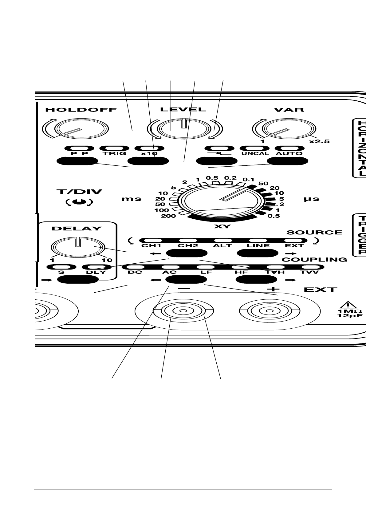
Figure 4
14
27
21
28
19
20
22
23
24 26 25
13 16 15 18 17

30 MHz-differential o cillo cope
15
(26) - (25) EXT- EXT+ Input of the external synchronisation signal by the + and -
BNC sockets. (Refer to §. 5. SPECIFICATIONS).
(23) - (24) COUPLING - Coupling of the trigger source
The filtering activated only acts on the trigger channel, not on the display.
This COUPLING function is inactive in XY mode (indicators out).
Select by pressing on the (23) or (24) key:
DC coupling (0 to 40 MHz)
DC AC LF HF TVH
TVV
AC coupling (10 Hz to 40 MHz)
DC AC LF HF TVH
TVV
Rejection of ource ignal frequencie < 10 kHz
DC AC LF HF TVH
TVV
(facilitate ob ervation of ignal with a DC component).
Rejection of ource ignal frequencie > 10 kHz
DC AC LF HF TVH
TVV
(facilitate the ob ervation of ignal with HF-noi e).
Trigger on the ynchroni ation pul e of the TV line
DC AC LF HF TVH
TVV
(∗ NB, page 13).
Sweep coefficient recommended for the examination of a
TV line: 0.5 µ at 20 µ /div.
Trigger on the ynchroni ation pul e of the TV ra ter
DC AC LF HF TVH
TVV
(∗ NB, page 13).
Sweep coefficient recommended for the examination of a
TV ra ter: 1 m /div.
In TVH and TVV COUPLING, the P-P and LEVEL functions are inactive.
(14) P - P - Peak-to-peak trigger
The trigger reference (accurate adju tment by LEVEL) i automatically between
the low and the high peak of the inewave cho en, which guarantee the trigger
irre pective of the amplitude or the DC component of the ource ignal (80% of
the peak-to-peak amplitude of the inewave for f = 100 Hz).
This COUPLING function is inactive in XY mode (indicators out). The use of
P-P triggering is not recommended on very low-frequency signals or pulsed
signals of very short duration.
3.6. Trigger delay (DELAY)
Thi mode permit a portion of the ignal to be examined in detail (at high weep peed)
after the trigger event cho en. The DELAY command (27) enable continuou adju tment
of the delay (1 to 9 div.).
(28) DELAY- Select by pre ing ucce ively on key (28) :
Normal mode :
S DLY
The weep tart immediately (trigger event at the far left of the trace).
SEARCH mode (S) :
S DLY
The plot( ) on the creen pre ent an under-
inten ified part (equivalent to the
trigger delay) adju table u ing the DELAY potentiometer (27).
DLY delayed mode (DLY mode):
S DLY
The weep begin at the point corre ponding to the end of the under-
inten ified zone in SEARCH mode.
16
30 MHz-differential o cillo cope
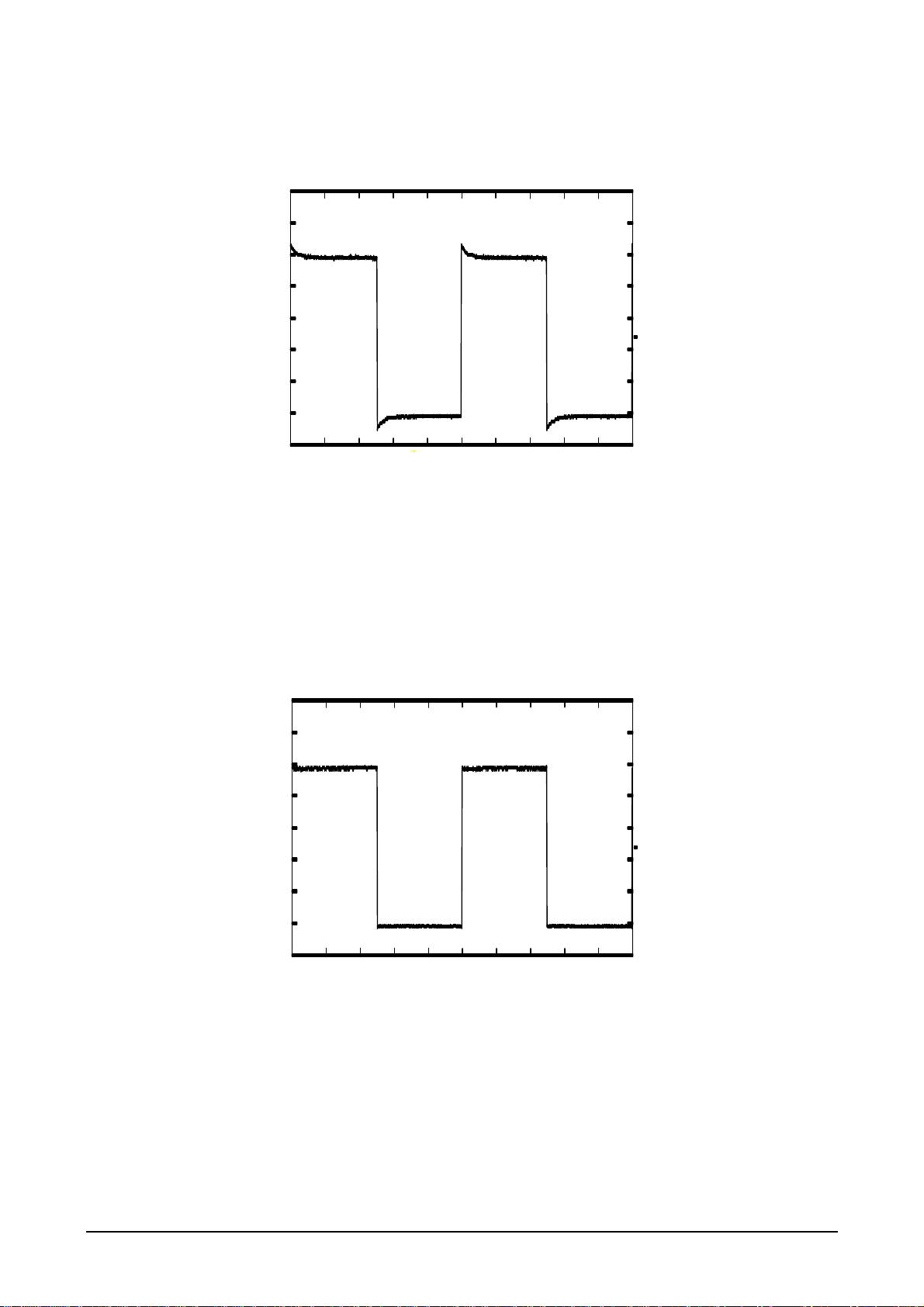
Figure 5 : Probe incorrectly compensated in
low frequency
Figure 6 : Low frequency compensation
correct

30 MHz-differential o cillo cope
17
4. APPLICATIONS
4.1. Visualisation of the calibration signal
- Connect the PROBE output (33) to CH1 input (34) by u ing a 1/1 or 1/10 mea urement
probe.
- Select the following function :
• CH1 en itivity (4) or CH2 (10): 0.1 V/div. (1/1); 10 mV/div. (1/10)
• Sweep peed (20): 0.2 m /div.
• Trigger ource (21) or (22): CH1 or CH2
• Trigger mode (19) : AUTO
- If nece ary, adju t vertically u ing the POSITION (6) or (11) control and tabili e the
trace u ing the potentiometer LEVEL (15).
- Adju t the low-frequency compen ation of the probe o that the impul e plateau i horizontal.
See figure 5 and 6.
To compensate, please refer to the instructions enclosed with the probe.
4.2. Measurement of amplitude and frequency
Amplitude and frequency might be measured from the PROBE output (33) whose
specifications are the following :
•Shape : rectangular
•Amplitude : 0 to + 2.5 V ± 1 %
•Frequency : 1 kHz ± 1 %
•Duty cycle : ½
- Connect the PROBE output (33) to the CH1+ (35) or CH2+ (29) input by using a 1/1 or
1/10 measurement probe.
- Adjust CH1 or CH2 sensitivity to 20 mV/div. (if a 1/10 probe) and the timebase to 1 ms/div.
- Check that the amplitude of the visualised signal is equal to 2.5 divisions and that its
period is equal to 1 division.

18
30 MHz-differential o cillo cope
5. SPECIFICATIONS
Only the value affected by tolerance or limit con titute guaranteed value (after half an
hour' warming up). Value without tolerance are given for information.
5.1. Vertical deflection
CH1 - CH2 Sp cifications Comm nts
Characteristics
Bandwidth at - 3 dB
> 20 MHz on range 10 mV to 50 mV/div.
> 30 MHz - 100 mV to 200 V/div.
mea ured on 6 divi ion
Ri etime
10 % 90 %
< 17 n on range 10 mV to 50 mV/div.
< 11.7 n - 100 mV to 200 V/div.
ignal 5 div.
Accuracy of vertical deflection
coefficient ( en itivity)
Max. peak voltage of common
mode
Sen itivitie :
10 mV to 200 V/div. ± 3 %
10 mV to 0.5 V/div. 20 V
1 V to 5 V/div. 200 V
10 V to 200 V/div. 600 V
14 po ition ,
equence 1-2-5
Variable vertical deflection
coefficient
Multiplication of V/div. range by 1 to 2.5
(amplitude reduction)
Calibrated po ition :
control in left-hand po ition
Input protection Protection againt tran ient 4 kV
(1.2 µ / 50 µ )
Input :
300 V CAT III
600 V CAT II
Limitation of the
F (frequency) level
from 0 to 2 MHz 600 V peak
from 2 to 30 MHz -2 dB/decade
Focu ed trace thickne 50 mV to 200 V/div. < 1 mm
10 mV and 20 mV/div. < 4 mm
Chopping frequency (CHOP)
≈ 200 kHz
AC coupling cutoff frequency < 10 Hz
Input impedance 1 MΩ ± 1 % // 12 pF
Re pon e in rectangular
ignal
Overflow < 3 %
Aberration at 100 mV/div. :
• on the plateau < 1 mm
• before the edge < 2 mm
Square ignal
1 kHz to 1 MHz
1 MHz
(Tm gene < 100 p )
Cro talk at 20 MHz 10 mV/div. to 50 mV/div. 30 dB typ.
100 mV/div. to 200 V/div. 36 dB typ.
Same en itivity
on CH1 and CH2,
amplitude 6 div.
Di play mode
NORMAL / DIFF CH1
NORMAL / DIFF CH2
CH1, ALT, CHOP, ADD, CH2, XY
CH1 the input -CH1 i inhibited in
normal mode
CH2 the input -CH2 i inhibited in
normal mode
ALT = alternate
CHOP = chopped
CH1 channel witching in
normal or differential
mode
CH2 channel witching in
normal or differential
mode

30 MHz-differential o cillo cope
19
5.2. Horizontal deflection
Charact ristics Sp cifications Comm nts
Sweep coefficient
Accuracy on all range
0.5 µ to 200 m /div.
± 3 % i. e. 18 po ition
Sequence 1-2-5
Expan ion x 10 Accuracy : ± 5 %
u ed to obtain 20n /div.
Variable coefficient
Divi ion of the /div. range
1 to 2.5 approx.
Calibrated po ition : control
at left-hand top
( ignal horizontal
expan ion)
Sweep di able time
(HOLDOFF)
Variable from 1 to 10 for each of the 18 range in
the timeba e
XY mode
Y bandwidth -3 dB
X bandwidth -3 dB
derating
0 to 20 MHz on range 10 mV to 50 mV/div.
0 to 30 MHz - 100 mV to 200 V/div.
0 to 2 MHz
∆ϕ < 3° to 120 kHz
5.3. Trigger system
Characteristics
Sp cifications Comm nts
CH1 / CH2 en itivity
0 to 10 MHz
10 to 20 MHz
20 to 40 MHz
0.7 div.
1 div.
2 div.
ALT Source depending on vertical
mode :
CH1 CH1 trigger
ALT CH1 then CH2 trigger
CHOP CH1 trigger
ADD CH1 trigger
CH2 CH2 trigger
LINE Synchro to main
EXT en itivity applicable min. amplitude • Ze = 1 MΩ // 12 pF
0 to 10 MHz
10 to 20 MHz
20 to 40 MHz
100 mVpp
200 mVpp
400 mVpp
• Protection again t tran ient
4 kV (1.2 / 50 µ )
• Common mode voltage
50 V peak max.
Filter Bandwidth to -3 dB
AC
10 Hz to 40 MHz
LF
10 kHz to 40 MHz
HF
0 to 10 kHz
TVH and TVV
ynchroni ation on a video line (TVH)
or video frame (TVV )
Horizontal mode
AUTO
Normal
relaxéd mode Freq > 5 Hz
triggered mode
Slope Falling edge
Ri ing edge
Level range
P-P
80 % of peak-peak amplitude of
inu oidal ignal F > 50 Hz
Normal
± 12 divi ion

20
30 MHz-differential o cillo cope
5.3.1. Trigger delay coefficient
Scanning tim rang D lay rang
(approx.)
0.5 µ /div. 0.5 µ to 5 µ
1 µ /div.
2 µ /div.
5 µ /div.
1 µ to 10 µ
2 µ to 20 µ
5 µ to 50 µ
10 µ /div.
20 µ /div.
50 µ /div.
10 µ to 100 µ
20 µ to 200 µ
50 µ to 0.5 m
100 µ /div.
200 µ /div.
500 µ /div.
100 µ to 1 m
200 µ to 2 m
500 µ to 5 m
1 m /div.
2 m /div.
5 m /div.
1 m to 10 m
2 m to 20 m
5 m to 50 m
10 m /div.
20 m /div.
50 m /div.
10 m to 100 m
20 m to 200 m
50 m to 500 m
100 m /div.
200 m /div.
100 m to 1
100 m to 2
5.4. AUTOSET function
Param t rs s arch d for
by AUTOSET
Configuration impos d
by AUTOSET
Unchang d param t rs
Pre ence of a ignal on
channel CH1 and CH2
PTP ynchro Horizontal and vertical po ition
Vertical en itivitie
adapted to the ignal
AC coupling of the channel
VAR
Time ba e range adapted
to the ignal
horizontal expan ion
coefficient: x1
DELAY
INTENSITY
AUTO canning FOCUS
5.4.1. AUTOSET specifications
The AUTOSET function i activated by pre ing the AUTOSET key; it automatically
earche for the vertical en itivity and the canning coefficient adapted to the
ignal pre ent on channel CH1 and/or CH2.
• Signal earch time approx. 5 econd
• Frequency range 25 Hz to 30 MHz
• Min. amplitude 200 mV
• Αutomatic witch to CHOP for T/DIV between 200 m and 1 m /div.
Table of contents
Other Metrix Test Equipment manuals

Metrix
Metrix MX 407 User manual

Metrix
Metrix CX 1651 User manual

Metrix
Metrix MX 407 User manual

Metrix
Metrix MX 435D User manual

Metrix
Metrix HandScope OX5022B User manual

Metrix
Metrix HI-903 User manual

Metrix
Metrix MTX 3352 User manual

Metrix
Metrix CX 1651 User manual

Metrix
Metrix GX 1025 User manual

Metrix
Metrix HI-903 User manual

Metrix
Metrix GX-1030 User manual

Metrix
Metrix DOX 2 Series User manual

Metrix
Metrix OX 6062-II User manual

Metrix
Metrix MTX 3252e-C User manual

Metrix
Metrix PX 110 User manual

Metrix
Metrix DOX3104 User manual

Metrix
Metrix HX0074 User manual

Metrix
Metrix MTX 162UE TX 162UE User manual

Metrix
Metrix MX 67 User manual

Metrix
Metrix MX 59HD User manual


