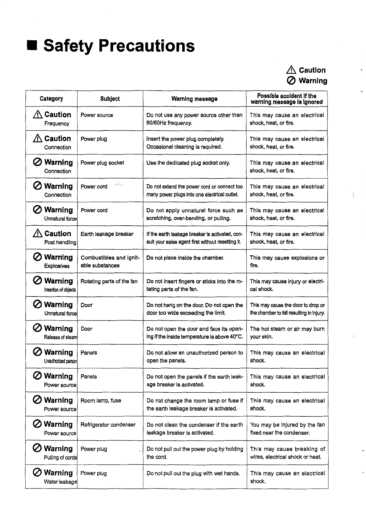
Etac HIFLEX A Series User manual

Temperature and Humidity Chamber
HIFLEX®
Series
A I f a
I
Temperature
(&
Humidity) Chamber
Operation manual
,~\I..
c,
• When using our products, please first read this operation manual carefully .
• Please keep this operation manual at a convenient place so that you may
refer to it whenever you need.

",Il"

Preface
Thank you very much for purchasing our HIFLEX a series Temperature
(& Humidity) Chamber. This a series was developed utilizing ETAC's
original technologies and taking the current market trends into consid-
eration. We believe that this series will meet your various needs.
..,
In order to use all functions of this product effectively, correctly, and
safely, please first read this operation manual carefully to fully under-
stand the features and operation methods.
This manual contains information on all HIFLEX a series products. Please
organize information based on your purchased model.
Lot No. of this product is:
I
LOT No.
I
III
I
I I I I I
1. The "lot No." is also indicated on the lower
right of the front panel of the chamber for
your easy reference.
2. When contacting us regarding a chamber,
please remember to provide us with the
"Lot No." as well.
September, 2004 First edition issue

-
-.
'
~
,.

II
For Safe Use
When using a HIFLEX a series chamber, please first read this operation manual carefully to ensure correct and safe
operations. Please keep this operation manual at a convenient place so that you may refer to it whenever you need .
• Our Warning Labels
We have the following types of warning labels.
A
)::£ ~
CAUTION
A
).::£ ~
CAUTION
(g)ti"*~.
ffii.~~
.~i!l1lIfi
MOVING PARTS!
TURN OFF POWER
BEFORE CHECKING
i:U~I~ .• ~~~M
1S@m~iI:
DONT CHARGE FLAM-
MABLE; EXPLOSIVE
SUBSTANCES INSIDE
HOT SURFACE!
A
'*~
it
DANGER
KEEP OUT OF
CHAMBER
A
).::£ ~
CAUTION
ELECTRIC SHOCK!
~~m~,,*O)
lMq~D:~iI:
DONT CHARGE HEAT-
GENERATING SPECI-
MENS INSIDE CHANBER
o
ifm
in ,;:
,ct~
-tmtm~BJ.ljI~
CfS~3j.
<
t~"i!!
t,
READ OPERATION MANUAL BEFORE
OPERATING
Note
If our warning label becomes unreadable due to stain or damage, please inform our sales
person in charge of your company so that you will receive a replacement (for a fee).
A
J® ~
OBSERVANCE
EARTH
[GROUND]
A
J®
B
OBSERVANCE
~~.~
qJ~YiM~~m
USE SPECIMEN
POWER SUPPLY
RELAY TERMINALS

II
Safety Precautions
&.
Caution
(2)
Warning
Category Subject Warning message Possible accident if the
warning message is ignored
&.
Caution
Power source Do not use any power source other than This may cause an electrical
Frequency SO/60Hzfrequency. shock, heat, or fire.
&.
Caution
Power plug Insert the power plug completely. This may cause an electrical
Connection Occasional cleaning is required. shock, heat, or fire.
(2)
Warning
Power plug socket Use the dedicated plug socket only. This may cause an electrical
Connection shock, heat, or fire.
(2)
Warning
Power cord
,"- ! ~,.
Do notextendthe powercordor connecttoo This may cause an electrical
Connection manypowerplugsintooneelectricaloutlet. shock, heat, or fire.
(2)
Warning
Power cord Do not apply unnatural force such as This may cause an electrical
Unnaturalforce scratching, over-bending, or pulling. shock, heat, or fire.
&'Caution
Earth leakage breaker Ifthe earthleakagebreakeris activated,con- This may cause an electrical
Post handling suityoursalesagentfirstwithoutresetting
It.
shock, heat, or fire.
(2)
Warning
Combustibles and ignit- Do not place inside the chamber. This may cause explosions or
Explosives able substances fire.
(2)
Warning
Rotating parts of the fan Do not insert fingers or sticks into the ro- This may cause injury or electri-
Insertion
of
objects tating parts of the fan. cal shock.
(2)
Warning
Door Do not hang on the door. Do not open the Thismaycausethedoorto dropor
Unnaturalforce door too wide exceeding the limit. thechambertofallresultingininjury.
(2)
Warning
Door Do not open the door and face its open- The hot steam or air may burn
Releaseofsteam ing ifthe inside temperature is above 40·C. your skin.
(2)
Warning
Panels Do not allow an unauthorized person to This may cause an electrical
Unauthorized person
open the panels. shock.
(2)
Warning
Panels Do not open the panels if the earth leak- This may cause an electrical
Power source age breaker is activated. shock.
(2)
Warning
Room lamp, fuse Do not change the room lamp or fuse if This may cause an electrical
Power source the earth leakage breaker is activated. shock.
(2)
Warning
Refrigerator condenser Do not clean the condenser if the earth You may be injured by the fan
Power source leakage breaker is activated. fixed near the condenser.
(2)
Warning
Power plug
,--,
Do not pull out the power plug by holding This may cause breaking of
Pullingof cords the cord. wires, electrical shock or heat.
o
Warning
Power plug Do not pull out the plug with wet hands. This may cause an electrical
Water leakage shock.

.& Caution
o
Warning
Category Subject Warning message Possible accident if the
warning message is ignored
o
Warning
Power plug Do not use the power plug if the connec- This may cause an electrical
Connection tion is loose. shock, short circuit, or heat.
,&Caution
Power plug When not using the chamber for a long This may cause heat or fire.
Dust time, disconnect the plug to prevent dust.
&
Caution
Earth leakage breaker Regularly check the operation and if it is This may cause an electrical
Operationcheck abnormal, replace it. shock.
,&Caution
Overheat protector Regularly check the operation and if it is This may cause heat or fire.
Operationcheck abnormal, replace it. ..
.&Caution
Specimen shelves Fix them correctly and firmly. Thismaycausedamageofspecimens
Installation orinjurytotheoperatorifshelvesdrop.
o
Warning
Specimen shelves Do not place specimens exceeding the Thismaycausedamageofspecimens
Weight specified weight. orinjurytotheoperatorifshelvesdrop.
o
Warning
Glass parts Do not rest your hand or apply force to This may cause breakage of the
Unnaturalforce the glass parts. glass or injury.
o
Warning
Refrigerator condenser Do not touch the thin fin while cleaning. This may cause injury to your fin-
Contact gers.
o
Warning
Door handle Do not hold other than the handle when This may cause injury if your
Handlingofthedoo closing the door. hand is caught in between.
o
Warning
Door opening, heat ex- Do not touch these areas with your hand This may cause burns.
Contact haust, heater terminals and avoid contact.
o
Warning
Exterior of the chamber Do not nail screws or rivets. This may cause a short circuit or
Modification electrical shock.
o
Warning
Chamber Do not climb or hang on the chamber. The chamber may fall causing
Weight injury or damage.
o
Warning
Specimens in the airtight Do not place inside the chamber. Thismaycausedamageduetofreezing
spectmens
container orahightemperatureexplosion.
(Installation and Disposal)
,&Caution
Installation site Select afloor which can properly withstand The chamber may fall causing
Floor load the weight of the chamber. injury or damage.
,&Caution
Installation site Install the chamber on a level floor. The chamber may fall causing
Level floor injury or damage.
o
Warning
Installation site Do not Install the chamber outdoors where Failure to do so may cause elec-
Rain water is exposed to rain water, etc. trical shock or short circuit.

(Installationand Disposal)
.&
Caution
o
Warning
Category Subject Warning message Possible accident if the
warning message is ignored
o
Warning
Installation site Avoid places which are prone to high hu- Failure to do so may cause elec-
High humidity, midity or moisture. trical shock or short circuit.
moisture
o
Warning
Installation site Install in a space away from equipment This may cause a malfunction or
Loud noises that may generate noise. a serious accident.
'&Caution
Transferring or installation Donotallowunauthorizedpersonsto perform This may cause electrical shock,
Installation
work
work suchwork.Pleaseconsultyourvendor. short circuit, or fire.
,&Caution
Transferring or installation First read the operation manual carefully. Failure to do so may cause an
Manual work unexpected accident.
'&Caution
Transferring or ilisfallation Make sure that D-class earth is properly This may cause an electrical
Grounding
work
work grounded. shock.
o
Warning
Storage and disposal of Do not store chambers outdoors where This may cause a short circuit or
Rain water chambers. they may be exposed to rain water. electrical shock.
o
Warning
Storage and disposal of Do not store chambers where young chil- This may cause death from suf-
Storagespace chambers. dren can easily access them. focation, etc.
,&Caution
Storage and disposal of Ask your vendor to dismantle or dispose This may cause injury or accl-
Dismantling chambers. of your unwanted chambers. dent.
and disposal
,&Caution
Cleaning and inspection Please wear gloves. This may cause injury.
Wearinggloves
o
Warning
Disassembling and alter- Service engineers or vendors only. Unau- This may cause electrical shock,
Disassembling nation thorized personnel are strictly prohibited. damage, or fire.
andalteration
(WhenTransferring)
...
o
Warning
When transferring the Do not damage the power plug or the This may cause electrical shock,
Damages to chamber code. short circuit, or fire.
the code
,&Caution
When transferring the First drain out water completely. Failure to do so may cause elec-
Draincompletely chamber trical shock or short circuit.
o
Warning
When transferring the Do not apply force on the glass parts, etc. This may cause injury.
Pushingglassparts chamber
,&Caution
When transferring the First remove all specimens from the cham- Failureto do so may cause dam-
Removal of chamber ber. age to the specimens.
specimens
,&Caution
When transferring the Please take necessary caution so that the This may cause injury.
Falling of the chamber chamber will not fall.
chamber

Table of Contents
Table of Contents
• List of Standard Accessories.......................................................... 1
• Names of Parts 2
• Preparation Before Use 3
• Installation site 3
• Connecting to the Power Source 4
• Precautions for Use 5
• Inspection Before Operation 8
;". 1 ~ '.
• Water Supply 10
• Water Supply Procedures....................................................... 10
• Roof Tank Drainage Procedures 11
• Cautions When Supplying Water 12
• Other Precautions 12
• Chamber Operation (1)
Functions and operation of the temperature (humidity) controller
(ETACOM-P type) for program operations 13
• Name of Parts (Operation Panel) 13
• Functions of Operation Panel Switches 14
• Menu Structure and Functions 14
• MENU 15
• MISC FUN 15
• OTHERS 15
• Abbreviations List................................................................... 15
• Buttons 15
• Constant operation.......................................................... 16
• Program operation 16
• Monitor 16
• Setting and Operating Procedures 17
• Setting and Operating Procedures for the Constant
Operation 17
1. Setting Temperature/Humidity 17
2. Automatic Start Setting 18
3. Automatic Stop Setting 19
I

Table of Contents
..·.ft,
4. Using Automatic Start and Stop Functions
Together..................................................................... 19
5. Manual Settings 20
5-1. Setting the Time Signal 20
5-2. Manual Settings of Refrigerator and Water
Supply/Drainage 20
• Settings for the Program Operation 22
1. New Program Setting and Operating Procedures 22
2. Setting the Wait Function 24
2-1. Program Operations with Test Time Setting
and Wait Function 25
2-1-1. Start Step with Test Time Setting and
Wait Function 25
2-1-2. Other Steps with Test Time Setting of
"0:00" 28
3. Repetition Setting 29
4. Setting the Time Signal 29
5. Setting Functions 30
5-1. Deleting Steps 30
5-2. Inserting Steps 30
5-3. Step Manual Settings 31
5-4. Setting Partial Repetition 32
5-5. Combining Repetition (entire program
repetition) and Partial Repetition 33
• Operating the Registered Program 34
• Editing and Operating the Registered Program 34
• Duplicating the Registered Program 36
• Deleting the Registered Program 36
• Setting the Timer 37
1. Setting Automatic Start/Stop functions 37
2. Using Automatic Start and Stop Functions
Together... 38
• Pause Function 38
• Starting a Test 38
• Types of Screens Displayed After the Test is Started 39
/I

Table of Contents
• Skip Function 39
• Hold Function 40
• Resetting the Elapsed Time 40
• Error 41
• Alarm 42
• Screen Operation Procedures While the Test is Running,
Stopped, or Paused. 43
• Constant Operation / Program Operation
- Common Screens - 43
1. Common Areas in Each Screen 43
1-1. Operation Type Indication Area 43
1-2. Test Conditions Display Area 43
1-3. Set Values Display Area 43
2. Test Progress Screen 44
2-1. Guidance Display Area 44
2-2. Detailed Test conditions Display Area 44
2-3. Buttons Display Area 45
3. List Screen (Only for Program Operation) 46
3-1. List Display Area 46
3-2. Guidance Display Area 46
3-3. Buttons Display Area 46
4. Graph Screen (Only for Program Operation) 47
4-1. Graph Display Area 47
4-2. Guidance Display Area 47
4-3. Buttons Display Area 47
• Changing the Settings During Operation 48
• Monitoring Function 49
• Total Elapsed Time 49
• Monitoring Data Display Area 49
• Operations Log 50
• Miscellaneous Functions 51
• Upper/Lower Limits Setting Function 51
1.Temperature/Humidity Monitoring on the
Rise/Decline 52
• Power Mode 54
11/

Table of Contents
.,'
'~,.
• Error Review.................................................................... 55
1. Displaying the Operating Conditions when Errors
Occurred or Alarm is Activated 55
• Contrast........................................................................... 56
• Keylock............................................................................ 57
• Other Settings 58
1. Room Lamp 58
2. Backlight 59
3. Temperature Adjustment 60
4. Time Adjustment 61
• Screen Mute Function 61
• Auto-escape Function 62
• Refrigerator Protective Function 62
• Restarting the Chamber after a Power Failure 62
• Chamber Operations (2)
Functions and operation of the temperature (humidity) controller
(ETACOM-C type) for constant operations 63
• Name of Parts (Operation Panel) 63
• Functions of Operation Panel Switches 64
• Description of Letters and Abbreviations Used in the LED 65
• Letters Used in the LED 65
• Abbreviations used in the LED........................................ 65
1.Temperature-related 65
2. Humidity-related 66
• Temperature/Humidity Setting and its Operation 67
• Automatic Start/Stop Setting and its Operation 68
• Setting Automatic Stop Function 68
• Canceling Automatic Stop Function 69
• Setting Automatic Start Function 70
• Canceling Automatic Start Function 72
• Using Both Automatic Start and Stop Functions 73
• Upper/Lower Temperature/Humidity Limits Setting and the
Operation 74
• Setting Upper Temperature Limit.. 74
• Setting Lower Temperature Limit.. 75
IV

Table of Contents
,
~
,.
• Setting Upper Humidity Limit.. 76
• Setting Lower Humidity Limit.. 77
• Setting Temperature/Humidity (Upper/Lower Limit)
Continuously 77
• Checking the Settings 78
• Checking Temperature/Humidity Settings 78
• Checking Automatic Stop/Start Time Settings or
Elapsed Time 79
• Checking Upper/Lower Temperature/Humidity Limits
Settings 80
• Error, Alarm 81
• If
an Error Occurs........... 81
• If
the Alarm is Activated 82
• Monitoring Function 83
• Refrigerator Manual Settings 85
• Checking Refrigerator Settings 85
• Refrigerator Manual Settings 86
• Setting Power Mode 87
• Checking Power Mode Settings 88
• Power Mode Settings 88
• Room Lamp Turn-Off Settings 89
• Refrigerator Protective Function 89
• Restarting the Chamber after a Power Failure 90
• Error / Alarm Display, Related Functions, and Remedies 91
• Error List 91
• Alarm List 97
• Setting Overheat Protector
(for the Protection of Specimens) 101
• External Output Terminal 102
• Error Diagnosis List.................................................................... 103
• Schematic Diagram of Major Electric Components 105
.• Maintenance and Inspection 106
• Regular Inspection 106
• Check Points for 1st Month Inspection 106
• Check Points for 3rd Month Inspection 107
v

Table of Contents
• Check Points for 6
th
Month Inspection 108
• Inspection upon Relocation 109
• Expendable Parts................................................................. 110
• Expected Service Life of Major Parts 112
• Schematic Diagram 113
• General Schematic Diagram 113
• Schematic Diagram of Water Circuit (FX and FH types) 114
• Schematic Diagram of Refrigeration Circuit......................... 115
• Power Connection Specifications......................................... 116
• Selection of Refrigerator 117
'".'
~
,
.
• Specifications Table.................................................................... 119
• High Temperature & High Humidity Chamber (FH type) 119
• Low Temperature & Humidity Chamber (FX type) 120
• Low Temperature Chamber (FL type) 122
• Controllable temperature / humidity range 124
VI

List of Standard Accessories
II
List of Standard Accessories
Model
Name of accessories Quantity Specifications
FX· FH FL
Portable tank 1Capacity: 25 liters
0
X
Shelves support 4SUS304
00
Shelf 2SUS304 3 mesh netting
0 0
Wet bulb wick 1 bag 12 pieces per bag. Sterilized.
0
X
Operation manual 1This booklet.
00
Electrical diagram 1
0 0
Warranty card
*
Note 1
1
00
Inspection certificate 1
00
Note 1:To be mailed within one week after the product is delivered.
1

Names of Parts
II
Names of Parts
Roof tank
(not available for
FL
model)
Door
Exhaust vent
Temperature (humidity) controller
(operation display panel)
Viewing window
Front service panel
Rear service panel
Overheat protector
(for the protection of specimens)
Power cable port (back)
Drain outlet (back)
Earth leakage breaker
Adjuster
External output terminal
Caster Air inlet Humidification water tube connection point
(not available for
FL
model)
2

Preparation Before Use
II
Preparation Before Use
• Installation site
;".
o
Install at a place free of direct sunlight and with good ventilation.
o
Install at a place with ambient temperatures of +5
Q
C to +35
Q
C
throughout the year.
o
Install at a place free from moisture and dust.
o
Do not install near combustibles, corrosive gases, and high-tem-
perature heat sources.
o
Install on a level floor. (Allowable levelness is within 2 mm.)
o
Install away from any equipment that may generate noise.
o
Secure space around the chamber as illustrated in order to facili-
tate ventilation and maintenance.
#08 type: 800 or more
#14 type: 800 or more
#24 type: 1000 or more
#34 type: 1300 or more
Unit: mm
*1 Please note that a minimum space of 600 mm is necessary
between the wall and the chamber when maintenance work
needs to be done that requires opening the back panel.
3

Preparation Before Use
• Connecting to the Power Source
..'. r..
o
The power source specification of this chamber is AC200V
±
10%,
3-phase, SO/60Hz.
o
As this device is equipped with a microcomputer, be sure that it is
properly grounded.
o
Please connect the power switch of the specified capacity between
the primary power source and the chamber's electrical cord.
*
For information of power switch capacity, cable and ground wire
diameters, please refer to "Power Connection Specifications" on
page 116.
Terminal 3-phase, 4 wire
R Power cord color: Red
SPower cord color: White
T Power cord color: Black
E
Power cord color: Green
4

Precautions for Use
II
Precautions for Use
o
Place specimens in such a manner that the air circulation in the
test area is not obstructed.
o
The chamber is not a clean room, therefore, it is not suitable for
tests which require dust-free test conditions.
o
Do not use specimens that emit corrosive gases because such
specimens deteriorate the materials of chamber.
o
Do not place any explosive or flammable substances (including
those listed on the next page) inside the chamber.
o
Avoid opening the door during temperature/humidity tests as it may
cause the dangers and injuries described below.
(1) High temperature/humid air may blowout and burn your skin.
(2) As the test area is heated, you may burn your skin by touching
metal parts, etc.
(3) The fire alarm may be activated if it is mounted on the ceiling
above the chamber.
o
If the chamber is used for low temperature / high humidity tests
continuously for a long period, temperature / humidity control may
become less accurate due to formation of frost around the cooling
coil. Regularly run the chamber at high temperatures to remove
such frost. (See "Error Diagnosis List" on page 103.)
o
When the chamber is operated with temperature setting only, hu-
midity is not controlled. For the specimen that requires strict hu-
midity control, please make sure to set the humidity as well.
5

Precautions for Use
o
If the maximum ramp-up
I
ramp-down rate is set, the actual tem-
perature
I
humidity may overshoot the set value as the maximum
capacity is engaged for such a setting. For the specimen which
requires strict temperature Ihumidity control, please make sure to
set the ramp-up Iramp-down time.
o
Do not turn on or off the power switch and other switches abruptly.
It may cause malfunction of the chamber especially when a hu-
midity test is performed .
......t •.
o
Explosive Substances
(1) Nitroglycol, nitroglycerine, nitrocellulose, and other explosive
nitrate esters.
(2) Trinitrobenzene, trinitrotoluene, picric acid, and other explosive
nitro compounds.
(3) Peracetic acid, methyl ethyl ketone peroxide, benzoyl perox-
ide, and other organic peroxides.
(4) Sodium azide and other metal azides.
o
Flammable Substances
(1) Combustibles
• Metal lithium, metal potassium, metal sodium, yellow white
phosphorus, phosphorus sulfide, red phosphorus, celluloids,
calcium carbide, lime phosphide, magnesium powder, alumi-
num powder, other metal powders, sodium dithionite (or hy-
drosulfite).
(2) Oxides
• Potassium chlorate, sodium chlorate, ammonium chlorate, and
other chlorates.
• Potassium perchlorate, sodium perchlorate, ammonium per-
chlorate, and other perchlorates.
• Potassium peroxide, sodium peroxide, barium peroxide, and
other inorganic peroxides.
• Niter, sodium nitrate, ammonium nitrate, and other nitrates.
6
Table of contents
Other Etac Test Equipment manuals