Witt BDP2 User manual

Revision: 16.02.2022
W 3552-6.02_160222_en
Page 1 / 21 MWi
Instruction Manual
BDP2
Please read this manual carefully before installing, commissioning or operating the BDP2
Intended use
The automatic oil return system BDP2 is solely intended to return refrigerant oil
in a refrigeration or heat pump system.
Safety requirements
Any work with refrigeration systems must be carried out by trained and knowl-
edgeable personnel. All safety regulations / EC-Material Safety Data Sheets and
codes of practice concerning the use of refrigerants must be adhered to.
Under no circumstances are the indicated temperature- and pressure-limitations
on the data plate to be exceeded!
From Rev. i of 07.01.2019, the 25 bar version of the BDP is safety approved up
to 120° C. However, a continuous operation at temperatures above 75° C consid-
erably decreases the lifetime of the Teflon materials used in the BDP. During
normal operation, these temperatures should not occur (see chapter 11).
Applicable standards and regulations for installing or operating refrigeration
plants, e.g., EN 378 must be adhered to.
Before work is carried out and screws are loosened, it
is important pressure has been entirely released from the BDP2
housing.
When opening the BDP2 a sudden evaporating of trapped refrigerant
may occur. Therefore, special attention must be paid to wearing pro-
tection clothing and safety glasses.
ATEX
The BDP2 without optional level sensor has no ignition sources and therefore it does not meet the definition of
devices according to the ATEX Directive 94/9 / EC. The basis for this is an risk assessment of ignition sources
according EN 13463-1, chapter 5.2. Even during possible occurring malfunctions there are no own potential igni-
tion sources present.
Terms of warranty
To prevent accidents and for the safe operation of the refrigerant plant no modifications or alterations may be
carried out to the BDP2 without written approval by TH. WITT Kältemaschinenfabrik GmbH.
All information for the safe operation and maintenance of the BDP2 is based on our experience and is to the best
of our knowledge.
Our liability or warranty is excluded, if:
•The instructions in this manual are not adhered to
•The BDP2 and its equipment were operated incorrectly or the handling was not in accordance with the
mentioned procedures
•The BDP2 is used for purposes other than that for which it was intended to
•Safety devices were not used or disconnected
•There have been modifications made without written approval
•The safety requirements were not adhered to during installation or operation

Revision: 16.02.2022
W 3552-6.02_160222_en
Page 2 / 21 MWi
Instruction Manual
BDP2
Scope of delivery / available sizes
There are three sizes of BDP2 available:
•BDP2-03 with 0,6 litre content and 0,3 litre transfer volume
•BDP2-14 with 1,7 litre content and 1,4 litre transfer volume
•BDP2-38 with 4,1 litre content and 3,8 litre transfer volume
A residue of 0,3 Litre oil charge will remain to avoid contamination.
Standard scope of delivery includes
•Threaded connection G1“ for refrigerant/oil supply
•Weld connection for hot gas
•Weld connection for refrigerant/oil discharge with
integrated check valve for a differential pressure of 3 bar
Optional scope of supply (accessories):
•Stop valve EA32/G1“-I resp. II (steel) or EA40/G1“ I resp. II (stainless steel) including threaded connection
•Threaded connection G1” (steel) or G1”-VA (stainless steel)
•Check valve for a differential pressure of 1 bar (as replacement of the standard check valve 3 bar)
•Adapter with gas equalization line (stainless steel)
•WITT regulating valve EE3 or EE6
•WITT flow heat exchanger DWR
•WITT oil fine filter ÖF-G1/4“
•Level switch [no ATEX approval]
•Flow Sight Glass (stainless steel)
Technical data
5.1 Pressure- / temperature-range
STANDARD
max. permissible pressure Ps
at t0100
max. permissible pressure Ps
at t075
Test pressure
PT
BDP2 –25 bar
-1,00 bar to 25,00 bar between -10°C and 120°C
-1,00 bar to 18,75 bar between -10°C and -60°C
43,50 bar
BDP2 –40 bar
-1,00 bar to 40,00 bar between -10°C and 75°C
-1,00 bar to 30,00 bar between -10°C and -60°C
65,60 bar
Hydrocarbon
Refrigerants [KW]
max. permissible pressure Ps
at t0100
max. permissible pressure Ps
at t075
Test pressure
PT
BDP2 –25 bar
-1,00 bar to 25,00 bar between -10°C and 120°C
-1,00 bar to 18,75 bar between -10°C and -60°C
43,50 bar
5.2 Working fluids/refrigerants
The BDP2 can be operated with all common refrigerants such as CO2, NH3, R134a, R404, R407c, R507, etc.,
and with common refrigerant oils such as Fuchs Reniso KC68 or S68, Shell G68 Clavus, Reflo 68 Petro Canada,
Arctic SHC 226 Exxon.
For the hydrocarbon refrigerants [KW]propane (R290), propylene / propene (R1270), butane (R600) and isobu-
tane (R600a) as well as their usual refrigerant oils, there is a BDP2 in specific embodiments. When using non-
soluble oils (particularly at below -30°C) the viscosity should ensure flowability at any time (see 6.1.1).
5.3 Materials
•Housing 1.4307
•Inner parts 1.0718
•Check valve 1.4305
•Weld connections 1.4541
•Gaskets Centellen
•O-Rings Neoprene
•O-Rings FKM-
LT170 for hydrocarbon refrigerants [KW]
•Screw connections A2-70

Revision: 16.02.2022
W 3552-6.02_160222_en
Page 3 / 21 MWi
Instruction Manual
BDP2
5.4 TIGHTENING TORQUE FOR SCREW CONNECTION
The screw connection of the BDP is tightened with a torque of 25 Nm.
5.5 Dimensions and connections BDP2
BDP2-03 BDP2-14
25 bar Part no. 3552.002001 25 bar Part no. 3552.002002
40 bar Part no. 3552.003001 40 bar Part no. 3552.003002
25 bar KW Part no. 3552.002101 25 bar KW Part no. 3552.002102
BDP2-38 BDP2-03 to BDP2-38
25 bar Part no. 3552.002003 25 bar
40 bar Part no. 3552.003003 40 bar
25 bar KW Part no. 3552.002103
Hot gas
connection
Oil
discharge
Hot gas
connection
Hot gas
connection
Oil
discharge
Oil
discharge
Required diameter
for installation D>206
Optional
level
switch
Optional
Level
switch
Optional
level
switch
Oil
inlet
Oil
inlet
Oil
inlet

Revision: 16.02.2022
W 3552-6.02_160222_en
Page 4 / 21 MWi
Instruction Manual
BDP2
5.6 optional equipment
Threaded connection G1“ EA32/G1“-I EA32/G1“-II
(for installation to a (Including threaded (Including threaded
different brand valve) connection G1”) connection
G1”)
25 bar
& 40 bar Part no. 6435.AJ0F00 Part no. 4111.AA7DJB Part no.4111.AA7DKB
Threaded connection G1“-SS EA40-SS/G1“-I EA40-SS/G1“-II
(for installation to a (Including threaded (Including threaded
different brand valve) connection G1”) connection
G1”)
25 bar
& 40 bar Part no. 6435.AF0F03 Part no. 4111.AA8MJD Part no.4111.AA8MKD
Adapter with gas-equalization line Level switch (incl. sealing system and cable)
Part no. 3552.000009 25 bar & 40 bar Part no. 4651.165102 25 bar & 40 bar
Gas equalization
Liquid
Hot gas connection
Filling level sensor
G ½“
ca. 113

Revision: 16.02.2022
W 3552-6.02_160222_en
Page 5 / 21 MWi
Instruction Manual
BDP2
Flow Sight Glass
Part no. 4551.AH3100 25 bar & 40 bar
5.7 Spare Parts
Hot gas connection
Oil
discharge
Mechanical valve
Part no.: 3552.002006
Set of gaskets
Part no.: 3552.006001
Set of gaskets KW
Part no.: 3552.006002
Check valve 3 bar
Part no.: 3552.000042
Alternative
Check valve 1 bar
Part no.: 3552.000043
Gasket
80/100x2 Centellen
Art.-Nr.: 3552.0000 06
O-ring –Neopren
75,87x2,62 –70SH
O-ring –Neopren
28x5 –70SH
KW: O-ring –LT170
28x5 –70 SH
Optional
level switch
Oil
inlet

Revision: 16.02.2022
W 3552-6.02_160222_en
Page 6 / 21 MWi
Instruction Manual
BDP2
Check valve Hot gas connection
O-ring –Neopren 19 x 4 –70SH
KW: O-Ring –LT170
19x4 –70 SH
Art.-Nr.: 5632.1A9AHK
Gasket 10/18x2 Centellen
Art.-Nr.: 6434.ACOD0 0
Check valve 3 bar
Part no.: 3552.000042
Alternative
Check valve 1 bar
Part no.: 3552.000043
Seal ring A –Alu –DIN 7603
Art.-Nr.: 5642.ABB L01
REMARK
The check valve is only the insert.
Body, gaskets, welding nipples and
coupling nut are not included.

Revision: 16.02.2022
W 3552-6.02_160222_en
Page 7 / 21 MWi
Instruction Manual
BDP2
DESCRIPTION OF OPERATION
6.1 Function
The BDP2 collects settled oil or oil-rich refrigerant and returns the oil after complete evaporation of remaining
liquid refrigerant in a heat exchanger back to the compressor.
6.1.1 non-soluble oils / ammonia systems
When using ammonia, the (conventional mineral) oil is collected at the lowest point of the evaporator or surge
drum, where the supply connection for the BDP2 should be made.
It is recommended to connect the BDP2 inlet for use in ammonia systems to the side of an oil-collecting
dome. A manual oil draining connection (with stop and quick acting valve) should be installed as well to
remove any contaminated oil during the first weeks after commissioning.
Evaporation temperatures below -30°C
From experience with ammonia systems, it is common knowledge that conventional compressor oils work well
above an evaporating temperature of –30°C. At lower temperatures the oil may become too viscous, which will
increase the time to fill and push out the contents. In such cases, a self-regulating heat trace cable wound around
the supply line and the BDP2 housing is recommended.
TH. WITT cannot accept any liability at lower ammonia temperatures or if there is any doubt about the viscosity
of the oil. In such cases, a right to return the BDP2 can be agreed with the manufacturer.
6.1.2 soluble oils / systems using synthetic refrigerants
It is also possible to return oil that is carried over from the compressor with the BDP2 when using soluble refrig-
erant oils.
In systems, using synthetic refrigerants the supply line to the BDP2 should be connected to an oil-rich
phase
–preferably in the evaporator return line. The amount of oil that is returned after evaporation of the remain-
ing liquid refrigerant should be equivalent to the amount that is carried over from the compressor (passing
the oil separator). In common systems operated with synthetic refrigerants, the amount of oil dissolved in
the refrigerant is approximately 3% (miscibility gap should be considered).
6.2 Refrigerant/oil mixture supply
Oil, respective refrigerant/oil mixture must enter the BDP2 freely from the low pressure side of the refrigerant
system and any entrained gas should be able to raise back to the top. Therefore a connection DN 32 resp. DN
40 with matching G1” thread should be used. With respect to service work of the BDP2 a stop valve (e.g. WITT-
EA32/G1“-I or II) is recommended.
The required time to fill the BDP2 with refrigerant/oil mixture for systems using synthetic refrigerants is a few
minutes (approximately 4 –5 min.) and at least 30 minutes for ammonia systems, depending on the viscosity of
the used oil.
For installation to a smaller existing connection, an adapter with gas equalization line should be used. This is
available as an optional extra. Due to the smaller connection the filling time is increased because the viscosity of
the oil gets a larger influence.
6.3 Pressure build up
In order to push out the refrigerant/oil mixture, it takes approximately 1 to 10 minutes of refrigerant hot gas supply
with a differential pressure of minimum 4 bar (respective 2 bar with replaced check valve) into the BDP2.
Pushing out refrigerant/oil mixture can be observed and optimized using an installed side glass. The side glass

Revision: 16.02.2022
W 3552-6.02_160222_en
Page 8 / 21 MWi
Instruction Manual
BDP2
should be mounted in the return line between the BDP2 outlet and the DWR.
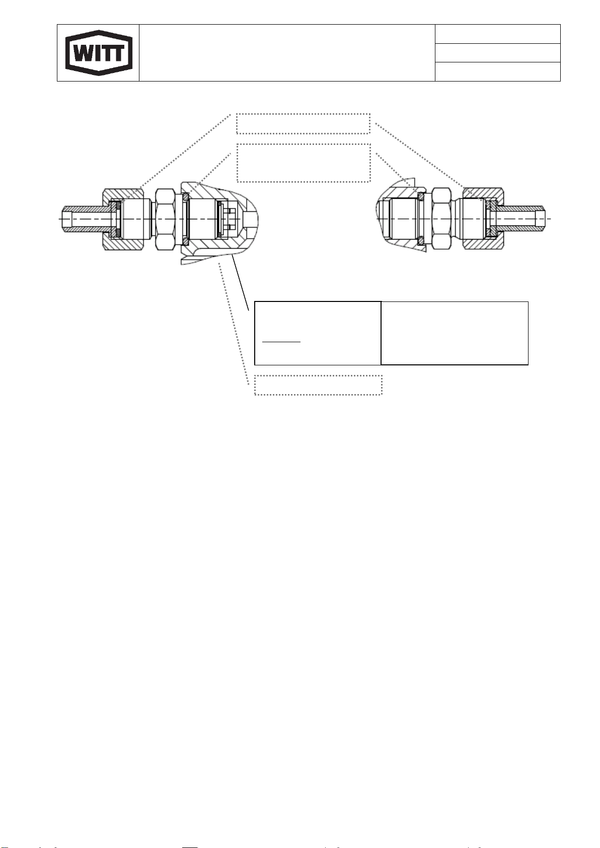
If you do not have hot gas with a differential pressure of at least 4 bar available, you should replace the standard
check valve. This check valve will open with a differential pressure of 1 bar. It needs to be ordered separately and
will be additionally delivered loose. This check valve is marked with a “1” next to the inlet connection.
6.4 Hot gas line
Preferably, the hot gas supply should be taken between oil separator and condenser (see “system schematic”,
6.10, tapping point A). Alternatively, aWITT high side float is suitable because warm gas is collected with sufficient
pressure at the top regulating valve (see “system schematic”, 6.10, tapping point B).
In both cases, the control line that is fed from a solenoid valve should be installed near to the BDP2, because
a) larger quantities of condensate may collect in front of the solenoid valve, but only refrigerant vapor is
allowed for the cycle.
b) The small volume of the control line between solenoid valve and BDP2 reduces the time for the return of
the internal piston (mechanical valve) to the initial position upon completion of a successful operation of
one cycle.
The internal damping of the BDP2 allows use of hot gas at high pressures.
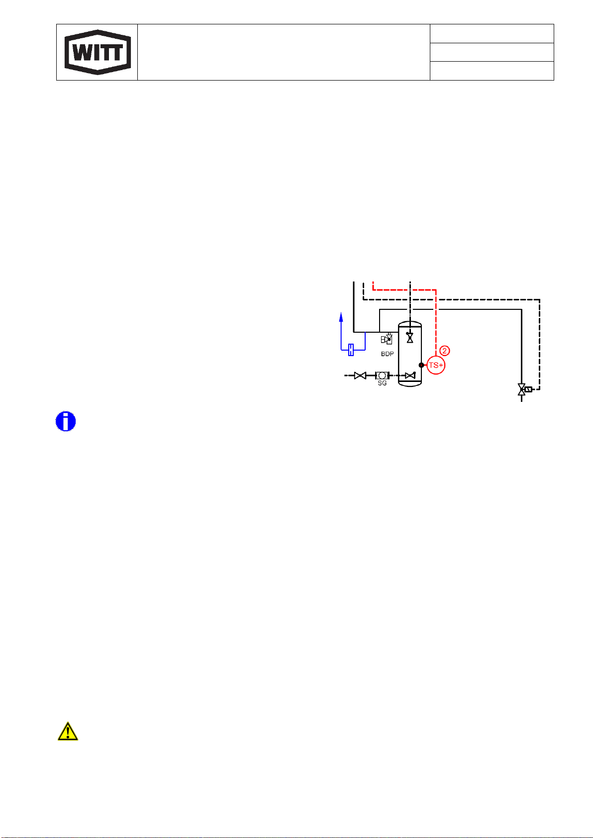
6.5 Discharge of refrigerant/oil mixture
Due to the hot gas supply, an internal piston closes the connection to the low-pressure side of the refrigeration
system and pressure is build up within the BDP2 housing. Any liquid within the BDP2 is pushed outwards through
a check valve towards the compressor side.
6.6 Heat exchanger at the BDP2 outlet
We strongly recommend to pass the pushed out refrigerant/oil mixture through a heat exchanger to ensure that
all liquid refrigerant has been evaporated before returned to the compressor. The heating capacity should be
adequately selected such that any liquid refrigerant is completely evaporated. Sufficient time for evaporating
should also be considered, when an optional level senor is used to control the cycle.
WITT flow through evaporator DWR or small oil collectors, heated electrically or with hot gas, are proven for this
purpose (see “system schematic”, 6.10, DWR).
6.7 Oil return to the compressor
The oil return should be located within or before the compressor, where the pressure is slightly lower than the
pressure within the BDP2 housing.
The engineer in charge of the design should select an appropriate location for the oil return –depending on the
type and make of compressor. The following locations have been proven good practice:
•Screw compressors: in the suction line right in front of the suction stop valve (see “system schematic”,
6.10, Position Y)
•Piston compressors: in the return line between oil separator and crank case (see “system schematic”,
6.10, Position X)
When using evaporation pressure regulators it is important that the pressure does not get too low. When the
pressure difference to open the check valve (3 bar respective 1 bar) is reached, it is possible to continuously suck
liquid refrigerant from the surge drum through the BDP2.

Revision: 16.02.2022
W 3552-6.02_160222_en
Page 9 / 21 MWi
Instruction Manual
BDP2
If a fine filter (e.g. WITT oil-filter ÖF) is required in the oil return line depends on the execution/cleanliness of the
entire system. This should be evaluated by the design engineer.
We recommend to install a sight glass after the heat exchanger. This will enable the proper observation of the oil
return.
6.8 repeating the cycle
Upon completion of the cycle, the internal piston (mechanical valve) will re-open the connection to the low-pres-
sure side. To enable the immediate opening, the BDP2 is internally connected via a small orifice with the low-
pressure side.
6.8.1 Closing the orifice (SPECIAL CASE)
While refrigerant/oil mixture is pushed out (for 1 to 10 min.)
a small amount of hot gas will escape through this small ori-
fice. If this amount is considered harmful (e.g. when installing
the BDP2 underneath a stand pipe with level switch) the ori-
fice should be closed (with a cylinder stud Ø 2 mm). The
pressure equalization between BDP2 and the pressure ves-
sel has to be done by an external equalization line after the
solenoid valve (see 6.4) to the low pressure side (gas area)
using an orifice of Ø 1,2 mm.
Connecting the BDP2 at the side avoids turbulences and carry over of dirt through the small internal orifice.
6.9 Controlling the cycle
The hot gas solenoid valve should be opened within an adjustable frequency of 1 to 10 min, depending on the
viscosity of the fluid.
When oil soluble refrigerants are used, a BDP2 with larger content and more frequent cycles will be required.
In systems with synthetic refrigerants the control cycle has to be adjusted depending on the operation time and
may need up to 10 cycles per hour depending on the oil carry over of the compressor.
When operating an ammonia system a small BDP2 is normally suitable with 1 to 6 cycles per day.
If the refrigeration / heat pump system is operated with only one compressor, or multiple compressors with one
oil compensation line, the simplest method is to use a time control. (see “system schematic”, 6.10, control 1).
Alternatively, the control of the cycle can be done using a level switch (see “system schematic”, 6.10, control 2).
When using multiple compressors with individual oil circuit (without oil equalization line), it is required to use a
demand control activated by the level control of the oil reservoir of the compressor. (see „system schematic“, 6.10,
control 3). To achieve that the demanding compressor is supplied with sufficient oil it is necessary to install a
solenoid valve in each return line. It is important that only one compressor is supplied with oil at a time. Make sure
no liquid can get trapped between the closed solenoid valve and the check valve behind the BDP2.
The control system needs to consider the time needed to fill again the BDP2. Therefore the safety low
level is not suitable for the demand control. It may be necessary to add a further level switch in the oil
separator.
To the low pressure side
Detail of 6.10 System Schematic

Revision: 16.02.2022
W 3552-6.02_160222_en
Page 10 / 21 MWi
Instruction Manual
BDP2
6.10 System schematic
Explanations:
Possible Control 1 = clock timer
Possible Control 2 = level switch
Possible Control 3 = level control
Tapping Point A = Hot gas supply through regulating valve EE3 or EE6 and
Hot gas solenoid valve DN3 at oil separator
Tapping Point B = Hot gas supply through regulating valve EE3 or EE6 and
Hot gas solenoid valve DN3 at WITT high side float regulator HR or HS
DWR = heat exchanger WITT DWR, if required with oil filter
X = return position piston compressor
Y = return position screw compressor

Revision: 16.02.2022
W 3552-6.02_160222_en
Page 11 / 21 MWi
Instruction Manual
BDP2
Shipping and storage
All openings (connections, etc.) are covered with yellow protection caps to prevent the intake of moisture or dirt.
Storage shall be dry and protected from any dirt or debris.
During transportation, the BDP2 should be protected in an adequate way to prevent damage.
Installation
Before installation the BDP2 should be visually inspected for any shipping damage.
Allow sufficient space for inspection and servicing. Provide at least 20 cm underneath the BDP2 for easy removal.
Furthermore, a diameter of at least 20,6 cm space should be considered in order to be able to rotate the BDP2 in
the G1” connection for removal.
For installation of the BDP2 it is required that a G1“ threaded connection with the opening facing down is available.
With regard to servicing larger refrigeration systems it is recommended to use a stop valve (WITT EA32/G1”-I or
II)
in conjunction with the G1” threaded connection mentioned above.
If required the positions of the hot gas and oil return line connections of the BDP2 can be modified. Therefore, the
12 cylinder screws need to be taken out such that the head can be turned according to the hole pattern. Upon
positioning of the connections, the head and body of the BDP2 need to be re-assembled. Make sure the cylinder
screws are tightened again with a torque of 56 Nm.
Before installation, the G1“ threaded ring of the BDP2 should be turned all the way down. The threaded ring
together with the O-ring acts as a stuffing box screw connection. When the BDP2 is entirely screwed into the
existing G1” connection, the BDP2 should be positioned and sealed with the threaded ring/O-ring. Therefore the
threaded ring has a cross hole for utilizing of a 6 mm Allen wrench.
To continue with the piping the hot gas and oil return line connections of the BDP2 are equipped with welding
sockets (see dimensions on the right side)
When long oil return lines are required, or when low differential pressures are present,
a lager diameter is necessary depending on the pressure loss. Based experience it is
not recommended to use an inner diameter of at least 9mm (e.g. seamless pipe ø13,5
x 2.3). It is possible to use larger diameters when reducers are installed. The selection
should be made by the project engineer at the planning state taking pressure loss, dif-
ferential pressures, viscosity and temperatures into account.
Make sure the installation is stress-free when welding to the connections.

Revision: 16.02.2022
W 3552-6.02_160222_en
Page 12 / 21 MWi
Instruction Manual
BDP2
8.1 Assembly of sealing joints
It is not possible to make a general statement about tightening torques for connections with seals because they
depend on various factors depending on the application.
Relevant factors for the tightening torque are, for example:
•Pressure
•temperature
•Medium (gas or liquid [high or low viscosity])
•Size of the installation space (of the seal)
•Surface roughness and tolerances of the installation space
•Gasket material (neoprene or centellated)
•Shore hardness of the gasket
•Cross-section of the gasket (flat or circular)
•Dirt and no residues in the installation groove or on the O-ring
•...
An experienced, knowledgeable installer trained in the use of refrigeration systems should be able to tighten a
joint with a gasket without specifying a tightening torque (without a torque spanner) so that it is tight.
The following general measures should be observed when mounting an O-ring:
•Break all sharp edges, use mounting sleeves or tape off threads.
•Cleanliness during assembly
•Use assembly grease
•Check O-ring sizes before fitting
•Mount with care
•Tighten gasket only enough to ensure tightness in operation
After tightening the gasket connection, the tightness should be checked with a leak detection spray or by a lit-
mus test when the refrigeration system is put into operation and tightened more strongly if necessary.
The same measures and procedures apply to flat gaskets made of Centellen.

Revision: 16.02.2022
W 3552-6.02_160222_en
Page 13 / 21 MWi
Instruction Manual
BDP2
8.1.1 Recommendations for tightening torques
The specified tightening torques are recommendations for the sealing connections of the BPD2, which were de-
termined under the following boundary conditions:
•- Ambient temperature 20°C
•- Test pressure 66 bar
•- Bubble detection method DIN EN 1779 - C1, test time approx. 5 minutes
with optional sensor

Revision: 16.02.2022
W 3552-6.02_160222_en
Page 14 / 21 MWi
Instruction Manual
BDP2
Nr.
component
position
descripiton
Key width
Tightening torque
1
1.1
O-Ring 28 x 5
-
-
1.2
Threaded ring G1“
SW 41
25 Nm
2
2.1
Cylinder screw
M12 x 55 —A2-70
SW 10
56 Nm
.2
Flat gasket
80/100x2 - Centellen
-
-
3
3.1
O-Ring
19 x 4
-
-
3.2
GEV
G ½“
SW 27
25 Nm
4
4.1
Union nut
G ½“ – VA
SW 27
50 Nm
with open-end spanner on
3.2 Counterhold
4.2
Flat gasket
10/18x2 - Centellen
-
-
5
5.1
O-Ring
19 x 4
-
-
5.2
Screw plug
G ½“ – VA -gsz
SW 19
20 Nm
6
6.1
O-Ring
19 x 4
-
-
6.2
optional
level sensor
SW 27
max. 25 Nm

Revision: 16.02.2022
W 3552-6.02_160222_en
Page 15 / 21 MWi
Instruction Manual
BDP2
8.2 BDP2 CONNECTION
The weight of the BDP2 and vibrations in refrigerant system may cause damages to the weld connection of the
BDP2. For example, this may occur if the lever arm is too long.
Therefore, the BDP2 should be supported by additional appropriate structures (e.g., bracing, cold clamp
with connection to the frame or similar measures).
Prior to commissioning
Commissioning and start up of the BDP2 is not permitted until a safety analysis of the entire refrigeration installa-
tion has been carried out.
On completing installation of the BDP2, the refrigerant plant must be pressure tested. Records of the testing must
be kept in a safe place. The BDP2 system should be vented and connected to the main plant.
9.1 Charging the system
Charging refrigerant oil will make it possible to observe whether the oil return is working properly and the
compressor will not shut down due to lack of oil.
9.1.1 Ammonia System
In ammonia systems the BDP2 and the heat exchanger should be filled with compressor oil.
9.1.2 Synthetic Refrigerant System
It is recommended to charge systems operating with synthetic refrigerants with approx. 3% refrigerant oil in the
low-pressure side (attention with the miscibility gap).
Commissioning
The refrigerant / heat pump system should be started-up without the BDP2, to make sure any dirt is flushed out
off the system. It is recommended to wait until the oil of the compressor has been changed for the first time to
make sure most of the dirt is removed.
Check that
•the max. allowable pressure is not exceeded (see data plate)
•the pressure in the BDP2 housing cannot increase more than 3 bar above the lowest possible pressure
in the compressor suction line (particularly during stand-still, with two-stage systems and with open econ-
omizers)
•all pipes are connected correctly according to the technical drawings.
OPERATION
During operation the free supply of oil respectively refrigerant/oil mixture into the BDP2 must be provided, as
mentioned in sections 6.1 and 6.2.
Formation of condensate or frost indicates the liquid refrigerant/oil level within the BDP2. Since the BDP2 is man-
ufactured using stainless steel, there is no danger of corrosion. In some cases it can be favourable to install a drip
pan under the BDP2.
The hot gas solenoid valve should be activated over a period of 1 to 10 minutes–depending on the size of the
BDP2 and the system concept (time or demand control) –to push the liquid content out of the BDP2. The timer
can be adjusted by observing the outlet temperature and system conditions.

Revision: 16.02.2022
W 3552-6.02_160222_en
Page 16 / 21 MWi
Instruction Manual
BDP2
Intended operation conditions
Usually, the hot gas for pushing out the content is removed from behind the oil separator and not immediately
behind the compressor. At the beginning of the ejection the BDP is working at the evaporation temperature and
the process is limited to a maximum of 10 minutes (or the time is adjusted to <10 minutes by observing the outlet
temperature)
In practice, the hot gas supply will only take place until the temperature rises in the BDP (for energy saving
reasons). An increase of the operation temperature to above 75°C should be excluded during intended operation.
If there are any concerns (f.e. at short hot gas supply line, long set ejection time and high hot gas temperature at
the point of delivery), a port behind the condenser should be chosen (for example, at the upper service valve of
the high pressure float controller).
Maintenance and Inspection
The BDP2 should be visually inspected according to EN 378-2 on a regular basis.
Any work with refrigeration systems must be carried out by trained and knowledgeable personnel. All safety
regulations and codes of practice concerning the use of refrigerants must be adhered to.
Prior to any maintenance work and loosening of any screws, make sure the housing has been vented
correctly and all refrigerant is removed correctly.
When opening the BDP2 a sudden evaporation of trapped refrigerant may occur. Therefore, special atten-
tion must be paid to wearing of protection clothing and safety glasses. Never remove any screws when
there is a possibility of refrigerant or pressure remaining in the system.
The BDP2 is designed to operate without the need of regular maintenance work.
In case of contamination, it is possible to disassemble the BDP2 for cleaning or replacement of parts. During re-
assembly all gaskets should be replaced.
Besides the following recommended test, there is no further work required.
12.1 Function control
During operation, the proper functioning of the internal piston (mechanical valve) can be recognized when the
piston moves down. Due to the internal damping, it is not easy to recognize when the piston is moving up.
A side glass behind the BDP2 is recommended to be able to visually check whether the refrigerant/oil
mixture is pushed out.
12.2 Check of the internal orifice
To enable the immediate opening upon finishing the cycle, the internal piston is equipped with a small orifice
(hole). It may be necessary to clean this hole when it has got contaminated.
The blocked hole of the piston can be recognized when the BDP2 remains warm at all times. (Normal
operating conditions will result in alternation of frost and condensate). If the hole is blocked the internal
piston will prevent proper supply to the BDP2.

Revision: 16.02.2022
W 3552-6.02_160222_en
Page 17 / 21 MWi
Instruction Manual
BDP2
12.3 Exchange of the check valve
In the discharge connection is a small check valve that can be removed, when a 1 bar pressure difference instead
of 3 bar is required (see chapter 6.3). It is possible to exchange the check valve.
12.4 DISCHARGING AND DISASSEMBLY OF THE BDP2
1. Close the stop valve in front of the BDP2 (see system schematic 6.10) such that oil/ mixture cannot
longer enter
2. Wait until 1 to 2 cycles of the BDP2 are completed, to make sure the housing is completely empty.
3. Warming up the housing of the BDP2 will evaporate any remaining liquid refrigerant.
4. Close the valve behind the BDP2
5. Carefully release the pressure of the BDP2
It is fairly easy to release the pressure inside the BDP2 by using a service valve right in front of the hot
gas connection. Refrigerant gas can be drained into a bucket of water. This service valve is also suita-
ble to evacuate the BDP2 upon re-assembly.
The BDP2 must be without any pressure before disassembly!
6. Taking out the BDP2 (see also 8. assembly)
a. Loose the connections of all pipes
b. Loose of the G1“ threaded ring
c. Unscrew the BDP2 from the G1“ coupling
12.5 Cleaning the BDP2
To clean the BDP2 it is sufficient to take the valve head off by unscrewing the container. Then it is possible to
remove any dirt by blowing out (with air) or rinsing the internals.
Orifice

Revision: 16.02.2022
W 3552-6.02_160222_en
Page 18 / 21 MWi
Instruction Manual
BDP2
12.5.1 Disassembly of the valve mechanism
In case the valve mechanism should be pushed out, e.g., when clean-
ing the BDP2, it is important to first remove the circlip at the bottom
(see picture).
Thereafter, the valve head of the BPD2 should be placed on an appro-
priately sized tube (or similar). To avoid any damages the internal
valve mechanic should fall on a soft mat or cloth.
Then, the valve mechanism can be pushed out of the valve head by
gently knocking on a plastic rod (or piece of wood) with a hammer (see
picture). ATTENTION: Do not use metallic rods to avoid damages!
When reassembling the valve mechanism, it is strongly recommended
to replace the two O-rings.
When internals have been cleaned, the BDP2 (valve head & container)
can be reassembled.
It is important the cylinder screws are re-tightened
with a torque of 56 Nm.
The tight installation should be checked upon
successful re-assembly into the system (see also
9.).
Circlip
Soft pad
Tube
O-ring
Plastic rod

Revision: 16.02.2022
W 3552-6.02_160222_en
Page 19 / 21 MWi
Instruction Manual
BDP2
12.5.2 DISASSEMBLY OF THE CHECK VALVE
When cleaning the BDP2 it is recommended to check
and clean the check valve at the same time.
In order to have access it is necessary to screw out the
entire insert. Afterwards, the check valve can be
screwed out of the adapter.
Now it is possible to check and clean all parts.
When reassembling the check valve, all gaskets, the
O-ring, and the aluminum gasket ring should be re-
placed.
Upon successful inspection and cleaning, the check
valve can be re-assembled.
Check the system for tightness (see 12.5.1)
Optional filling level sensor [no ATEX-permission]
13.1 Supply schedule
•Filling level sensor (calibrated for liquid NH3)
incl. sealing system
•Cable box M12 plug-in connector
straight with 5 m cable
13.2 Functional description
The filling level sensor is installed in the highest place
inside the BDP2-container. When the oil reaches the level of the sensor, the LEDs change their colour from green
to yellow and the solenoid valve inside the hot gas line opens, by which the oil discharge is released.
13.3 Planning
Technical data
Supply 18…30V DC
Output PNP
Output function NO (open at zero current)
Output current max. 50 mA
The 4 LEDs light up in green, when the sensor is surrounded by cooling agent.
The output function at pin 2 & 3 is NO (open at zero current). There should be a signal (Pin 2&3 closed), when
the sensor is surrounded by cooling agent.
The sensor distinguishes between cooling agent (electro-conductive) and gas/oil (both not electro-conductive),
so that the electric signal of the sensor changes as soon as the medium changes.
A detailed description of the senor is found in the operating instructions “NH3- filling level sensor
(W4651-6.12)“. The operating instructions BDP2 (W3552-6.02) shall only be valid in connection with
the mentioned operating instructions W4651-6.12.
SW27
O-ring - Neopren
KW: O-Ring
LT170
Art.-Nr.: 5632.1A9AHK
Gasket
Art.-Nr.: 6434.ACOD0 0
Check Valve
Seal ring Alu
Art.-Nr.: 5642.ABB L01
Support for CV

Revision: 16.02.2022
W 3552-6.02_160222_en
Page 20 / 21 MWi
Instruction Manual
BDP2
13.3.1 Electric connection
The following connection possibilities of the filling level sensor are recommendations and are not binding.
TH.WITT shall not assume any liability for correctness of the connection diagrams. The operating instructions of
the manufacturer shall be applicable.
Proper connection shall be the responsibility of the user.
Without PLC
With PLC
In both cases the component to be controlled is the solenoid valve in the hot gas line.
13.4 Mechanical installation
Delivery condition BDP2 BDP2 with optional filling level sensor
The following points are to be observed at installation of the filling level sensor:
•remove the locking screw and the o-ring (container must be pressureless).
•do not use additional sealing material (e.g. PTFE-tape). The sensor must have electric contact to the
metallic process connection.
•lightly grease the thread of the sensor with a lubricating paste suitable for the current kind of application.
•the sensor is supplied with a sealing system already mounted.
•the maximum tightening torque (hexagonal SW27) is 20 … 25 Nm.
•After the assembly check BDP2 for tightness.
13.5 Putting into operation
For operation of the BDP2 with filling level sensor a sufficiently long discharge time is needed (also see operating
instruction BDP2 figure 6.9).
A clear recommendation as regards the discharge time is not possible, as it changes depending on the size of
the BDP2, the cooling agent, the cooling agent oil, the actual viscosity as well as the temperature.
The necessary discharge time can quite easily be observed and optimized through an inspection glass at the
outlet of the BDP2.
The next cycle must not take place at the end of the discharge, in order to give the BDP2 sufficient time
for refilling (see figure 6.6).
Hot gas connection
Locking screw
Hot gas connection
Filling level sensor
G ½“
ca. 113
Other manuals for BDP2
1
This manual suits for next models
3
Table of contents
Other Witt Industrial Equipment manuals
Popular Industrial Equipment manuals by other brands

Aerotech
Aerotech ATS150 Series Hardware manual

Festo
Festo DSNU-8 instructions

SAelen TS
SAelen TS GS/PUMA 35D operating manual

NRI
NRI Currenza H2 Hopper Series Technical documentation

Siemens
Siemens Power M12 Plug PRO Compact operating instructions

Ingersoll-Rand
Ingersoll-Rand Doosan XHP1070CM-1800 Operation Maintenance & Parts Manual