3
2. GEWÄHRLEISTUNGSBESTIMMUNGEN
2. TERMS
OF
WARRENTY
Zur Vermeidung von Unfällen dürfen an den Economizern we-
der Veränderungen noch Umbauten vorgenommen werden,
die durch die TH. WITT KÄLTEMASCHINENFABRIK GMBH
nicht ausdrücklich schriftlich genehmigt worden sind.
Diese Betriebsanleitung enthält die international genormten SI-
Maßeinheiten.
Alle Angaben und Hinweise für die Bedienung und Instandhal-
tung dieser Economizer erfolgen unter Berücksichtigung unse-
rer bisherigen Erfahrungen und Erkenntnissen nach bestem
Wissen.
In order to avoid accidents and ens re optim m perfor-
mance, no modifications or conversions may be carried o t
to the economisers witho t the explicit written approval by
TH.WITT KÄLTEMASCHINENFABRIK GMBH.
These instr ctions are based on internationally standard-
ised SI nits of meas rements.
All data and information on the operation and maintenance
of the economisers are provided based on o r extensive
experience and to the best of o r technical knowledge.
Eine Haftung oder Gewährleistung ist ausgeschlossen,
wenn:
die Hinweise und Anweisungen der Betriebsanleitung nicht
beachtet werden,
die Economizer einschließlich zugehöriger Einrichtungen feh-
lerhaft bedient werden bzw. deren Handhabung nicht dem
vorgeschriebenen Ablauf entspricht,
die Economizer entgegen ihrer Bestimmung zweckentfrem-
det genutzt werden,
Schutzeinrichtungen nicht benutzt oder außer Funktion ge-
setzt werden,
Funktionsänderungen jeder Art ohne unsere schriftliche Zu-
stimmung durchgeführt werden,
die einschlägigen Sicherheitsbestimmungen nicht beachtet
werden,
die Economizer unsachgemäß (zeitlich wie auch in der Aus-
führung) gewartet werden.
beim Austausch von Teilen bzw. für die Ersatzteilbeschaffung
nicht die vom Hersteller freigegebenen Originalersatzteile
verwendet werden.
Our liability or warranty is excluded, if:
The information and instr ctions in the operating man al
are ignored,
The economisers incl ding accessories are operated in-
correctly or are not installed according to the instr ctions.
The economisers are sed for p rpose other than that for
which it was designed.
Safety devices fitted are not sed or disconnected
There have been modifications made to the high press re
float reg lator witho t the man fact rers written approval
The safety reg lations are not adhered to
The economisers have not been maintained or repaired
properly (regarding timing and exec tion)
Parts that are sed d ring maintenance or service are not
the approved gen ine TH. WITT spare parts.
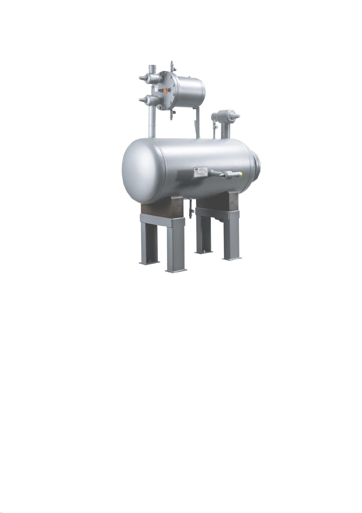
3. TECHNISCHE INFORMATION
3. TECHNICAL INFORMATION
Es sind verschiedene Economizer Modelle lieferbar: ECO2 bis
ECO4, die mit den passenden Hochdruckschwimmer-Regler
Modellen kombiniert werden können.
There several economiser models available: ECO2 to
ECO4. They can be combined with the matching float reg-
lators.
3.2 BESTELLANGABEN
Für die Auslegung der Economizer benötigen wir folgende In-
formationen:
Kondensationstemperatur ....[ °C]
Verdampfungstemperatur .....[°C]
Economizer- (Mittel-) Temperatur ....[ °C]
Kälte-/Wärmepumpenleistung ... [kW]
Wenn der Economizer bereits ausgewählt wurde sind bei der
Bestellung folgende Daten anzugeben:
Baugröße: ECO2 bis ECO4
Kältemittel: N- oder R- Kugel
Ausführung: -L, -M, -H, bzw. HS
Erforderliche Abnahmen/Dokumentation
Ggf. Auswahl Hochdruckschwimmer-Regler für Kompakt-
Einheiten
Sonderausführungen
3.2 ORDERINFORMATION:
For selection of yo economizer we will req ire the follow-
ing information:
Condensing temperat re …. [°C]
Evaporating temperat re....[°C]
Economizer (Intermediate) temperat re …. [°C]
Capacity … [KW]
When the econoizer is already selected, please specify the
following technical information when ordering
Size: Eco 2 to ECO4
Refrigerant: N- or R-ball
Exec tion: –L, -M, -H, or HS
Req ired standard of inspection and certification doc -
mentation.
Selected high side float reg lator, for nit assembly
Any special non standard req irements
ERSATZTEILBESTELLUNGEN
Die Schiebersteuerung betreffende Ersatzteile können nur als
gesamte Steuereinheit geliefert werden, da eine Justierung der
Teile erforderlich ist.
Bitte geben Sie Typ, Kältemittel und Baujahr an, wenn Sie
eine Steuereinheit bestellen:
z.B. ECO3 – M, NH
3
, 0 /96
Orderin replacement parts
Replacements parts for the slide valve control are only
available as a complete control nit, incl ding the ball float,
beca se all parts need to be adj sted.
Please indicate type, refri erant and year when ordering
a control nit:
3