Wizard MatDesigner 5000 Series Installation instructions

5000 HARDWARE GUIDE
Revision B
Model 5000
MatDesigner™

2
Wizard™ International, Inc., 4600 116th St. SW, PO Box 66, Mukilteo, WA 98275 888/855-3335 Fax: 425/551-4350 wizardint.com
NOTES:

\Manuals\5000Hardware
07/07/03
1
Series 5000 Hardware Guide
Hardware Guide for the Series 5000
Wizard™ Mat Cutting System
Contents
NOTES:.......................................................................................2
Chapter 1: The Board.................................................................................3
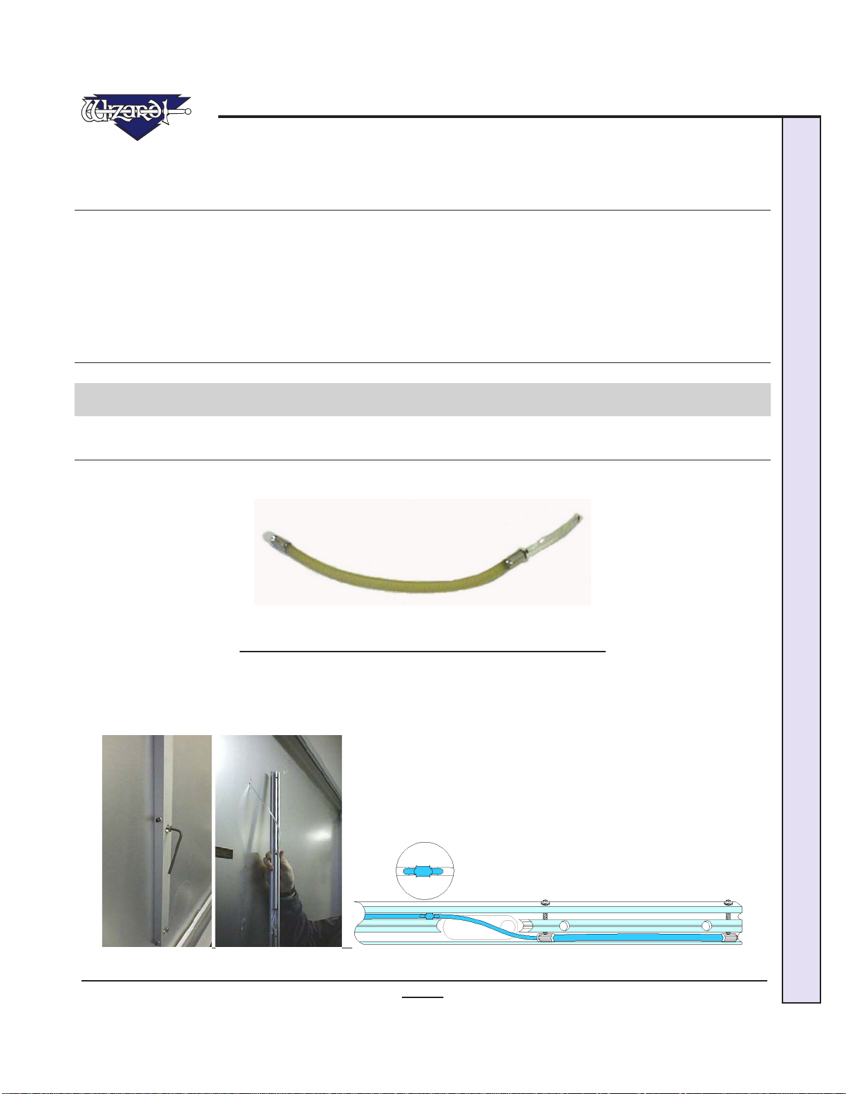
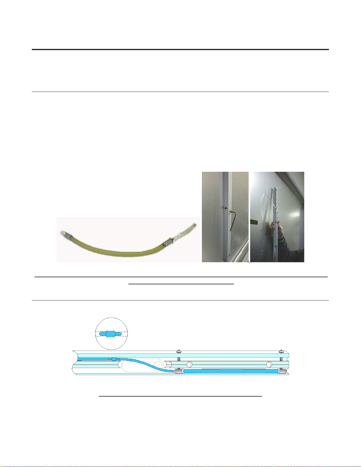
Air Clamp Removal...................................................................................................3
Air Clamp Temporary Fix..........................................................................................4
Air Clamp Replacement............................................................................................4
Air Clamp Test Button ..............................................................................................5
Gantry Alignment......................................................................................................5
Gantry Horizontal Tension .......................................................................................6
Travelling Cable.........................................................................................................7
Chapter 2: The CPU....................................................................................7
Modem Replacement................................................................................................7
Chapter 3: Driver Pak.................................................................................8
Driver Pak Replacement...........................................................................................8
No Power Available to the Driver Pak .....................................................................9
Chapter 4: The Gantry & Trolley Plate....................................................10
Gantry Alignment (See Board)...............................................................................10
Gantry Horizontal Tension (See Board)................................................................10
Gantry Removal.......................................................................................................10
Gantry Replacement...............................................................................................12
Gantry Wheel Adjustment ......................................................................................14
Trolley Vertical Tension..........................................................................................14
Trolley Plate Hinge replacement............................................................................15
Trolley Wheel adjustment.......................................................................................16
Chapter 5: The Head - Changing the Blade............................................16
Restarting the Cut...................................................................................................17

2
Wizard™ International, Inc., 4600 116th St. SW, PO Box 66, Mukilteo, WA 98275 888/855-3335 Fax: 425/551-4350 wizardint.com
Measure Blade Depth..............................................................................................17
Blade Depth adjustment.........................................................................................18
V-Groove Washer Installation ................................................................................18
Head Removal .........................................................................................................19
Head Installation .....................................................................................................20
Check Head Latch Allen Screw..............................................................................21
Check Plunge Speed...............................................................................................21
Plunge Speed Adjustment......................................................................................21
Chapter 6: Hardware Maintenance..........................................................22
Maintenance Schedule ...........................................................................................22
Daily:.......................................................................................................................................22
Weekly:....................................................................................................................................22
Monthly:..................................................................................................................................23
Ofoad the Air Regulator .......................................................................................23
Use a Surge Protector ............................................................................................24
Reboot Driver Pak when you reboot your CPU....................................................24

\Manuals\5000Hardware
07/07/03
3
Series 5000 Hardware Guide
5000 Hardware Guide
NOTE: DO NOT USE PLIERS when working on the board or its compo-
nents: ALL PARTS ARE ANODIZED. The exposed part of a scratch will
rub black marks onto the matboard! When screwing in parts with two
consecutive screws, screw first one part way, then begin the second.
It is important that they are screwed in at the same time so that there
is no uneven tensioning.
Chapter 1: The Board
Air Clamp Removal
When anAir Clamp blows, it needs to be replaced. Until the replacement arrives, remove the faultyAir Clamp then cut the blue
airline and insert a screw into airline and replace Clamp. Remaining Air Clamp will hold mat.
Fig A.
Fig A: Air Clamps are located inside Vertical/Horizontal Clamps
Turn off air supply. Move Gantry to the right until it stops. Determine which Clamp has blown and remove the Horizontal or
Vertical Clamp mounting screws with an Allen wrench (Fig B).
Gently lift Vertical/Horizontal Clamp to view small air hose tting. Lift tting from its groove and disconnect it by unscrewing
the two halves (Fig C-D). On later machines, simply pull the two hoses apart.
Fig B. Fig C. Fig D.
Fig B: Remove appropriate Vertical/Horizontal Clamp. Fig C-D: Remove damaged Air Clamp and replace with new Air
Clamp.

4
Wizard™ International, Inc., 4600 116th St. SW, PO Box 66, Mukilteo, WA 98275 888/855-3335 Fax: 425/551-4350 wizardint.com
Lay Vertical/Horizontal Clamp upside down to look at its construction. Loosen the two Allen screws at each end of the rubber
tube until you can pull the Air Clamp out.
Air Clamp Temporary Fix
Until the replacement arrives, follow these steps to keep working.
Determine if it is the Horizontal Clamp or the Vertical Clamp that has blown. If necessary, run a large mat without the Blade
in the Blade Cartridge (Blade Cartridge must be inserted in Head) and listen for air escaping.
Turn off the air supply. Remove the Horizontal or Vertical Clamp mounting screws with an Allen wrench (Fig B).
Gently lift Vertical/Horizontal Clamp to view small air hose tting. Lift tting from its groove and disconnect it by unscrewing
the two halves. On later machines, simply pull the two hoses apart.
Insert a screw into the airline and replace Clamp. This will keep up the air pressure to the remaining Air Clamp to hold the mat
in place until the replacement arrives.
Replace Clamp and turn on the air supply.
Fig A. Fig B. Fig C.
Fig A: Air Clamps are located inside Vertical/Horizontal Clamps. Fig B: Remove mounting screws. Fig C: Remove the
blown Air Clamp and replace with a screw.
Air Clamp Replacement
Place the metal end of the Air Clamp (side without hose) into slot closest to the end of clamp bar. Push the metal end rmly
into clamp bar and tighten the Allen screw (Fig A).
Fig A:
Fig A: Close-up of Air Clamp within the Vertical/Horizontal Clamp
Grasp the other side of theAir Clamp and stretch until the other metal ring can be inserted into its slot. Push the metal ring into
clamp bar and tighten the Allen screw.

\Manuals\5000Hardware
07/07/03
5
Series 5000 Hardware Guide
While holding Vertical/Horizontal Clamp near its mounting position, attach air tting and lead the air tting to its pocket. Slip
tting into its pocket as the clamp is being turned over into its mounting position. Align mounting holes and screw Vertical/
Horizontal Clamp back onto The Mat Cutter. Never use sharp instruments to clean out the Clamps or the Rails.
Air Clamp Test Button
Locate the Air Clamp Test Button by gently pulling out the left End Cap on the left literal side of the Board. Do not pull hard
or you may disturb the L-Bracket at the top of the Board. Inside, look for a plastic connector attached with several wires. This
is the Air Clamp Test Button.
Using a pen tip, press in on the small button (Fig A). This will inate the Air Clamps.
This is helpful in determining whether air is reaching the Air Clamps if they are not inating during the cutting sequence.
Fig A.
Fig A: Air Clamp test button is located within the left end cap of the Board.
Gantry Alignment
This is located in the Board Section because the Gantry Alignment adjustment is located on the Board.
L-click on Reset Motors (menu option) to disengage power to the motors. Pull Head and Trolley Plate down until it stops on
bottom rail. Pull Gantry to the left side of the Board until it stops.
Compare right edge of Gantry to right edge of Vertical Clamp (FigA). They should be even; a good alignment can be seen with
the eye or felt with your nger. These Two Surfaces Must Be Flush With Each Other From Top To Bottom. If the Gantry leans
to the left or right of the Vertical Clamp, Gantry needs straightening.
Look at the top and determine if Gantry is leaning to the left or right. Locate Gantry Alignment Screws. The Gantry Align-
ment Screws (two Phillips Screws) are located at the bottom right literal side of the board. The older machines have two knobs
instead of two screws.
If your Board has knobs, NEVER USE A TOOL (PLIERS) TO TURN the
KNOBS!!!

6
Wizard™ International, Inc., 4600 116th St. SW, PO Box 66, Mukilteo, WA 98275 888/855-3335 Fax: 425/551-4350 wizardint.com
Top of GANTRY leaning to LEFT:
Turn Front Alignment Screw Clockwise (one nearest front of board), and turn Back Alignment Screw Counterclockwise Equal
Distance (Fig B). Always loosen one screw before tightening the other. After each turn adjustment, push gantry full length of
the board several times and recheck Gantry alignment. Repeat as necessary.
Top of GANTRY leaning to RIGHT:
Turn Front Alignment Screw Counterclockwise (one nearest front of board), and Back Alignment Screw Clockwise Equal Dis-
tance (Fig C). Always loosen one screw before tightening the other. After each turn adjustment, push gantry full length of the
board several times and recheck Gantry alignment. Repeat as necessary.
Fig A. Fig B. Fig C.
Fig A: Line up Gantry to Vertical Clamp to determine which way the top of the Gantry is leaning. Fig B: Adjusting for
leaning to the left. Fig C: Adjusting for leaning to the right.
Gantry Horizontal Tension
This is located in Board Section because Gantry Horizontal Tension Adjustment is located on the Board.
The Gantry tension (back and forth) should move with 8-12 lbs. of pressure; a Fish Scale is useful in determining this. If Gantry
Tension is too loose, Gantry will move back and forth (over 3/16”) with Motors Engaged. Please call Wizard before making
adjustments to help prevent possibility breaking the Gantry Cable.
WARNING: If too much tension is applied to the Horizontal Tension Al-
len Screw, the Gantry Cable will break!
L-click on the Reset Motors (Button) to disengage Motors. Slide Gantry to left end of board. Look down the length of upper
rail from the left end; a ashlight may be needed to see long Gantry Cable inside the channel going all the way to the right side
of board.

\Manuals\5000Hardware
07/07/03
7
Series 5000 Hardware Guide
The Horizontal TensionAllen Screw is located on the upper right corner of the board (Fig A). Horizontal TensionAllen Screw
should be turned Clockwise (tightened) with a 3/16 Allen Wrench until Gantry Cable is almost straight, with just a little sag
in the middle. Pull the Gantry back and forth across full length of the board a couple of times to set the tensioning. Recheck
tension.
Fig A.
Fig A: The Horizontal Tension Screw is located on the upper right side of the Board.
Travelling Cable
Travelling Cable attaches to back of Gantry at the top; other end attaches to back of Board below Board Cable. Make sure that
there is no obstruction to the movement of the Travelling Cable. To check, move the Gantry/Head to the top of the Board then
move to the far right of the Board. If anything impedes movement, the Board will not function properly.
Chapter 2: The CPU
Modem Replacement
Turn off power to computer. Unscrew 4 screws on back of CPU holding cover; remove cover (FigA).
Fig A.
Fig A: Remove cover to CPU
Locate Modem by following phone line into back of CPU (plugged into LINE); unplug phone line.
Follow Modem to inside of CPU and unscrew small screw holding Modem in place. Slide old Modem out and remove it com-
pletely.
Insert new Modem in the same manner. Make sure it is Firmly Seated. Replace screw. Replace the cover and screws.
Plug phone line into Modem port marked LINE.

8
Wizard™ International, Inc., 4600 116th St. SW, PO Box 66, Mukilteo, WA 98275 888/855-3335 Fax: 425/551-4350 wizardint.com
Make sure phone line is plugged into port marked LINE.
Chapter 3: Driver Pak
Driver Pak Replacement
1. Turn off power to computer. Follow USB Cable from back of the Driver Pak (shoebox-size peripheral that says Wizard) to
where it plugs into the USB Port on the back of the CPU (Fig A).
Fig A.
Fig A: Connection of the Driver Pak to the USB Port
2. Turn off Driver Pak (ip toggle on back to “0”). Unplug USB Cable from USB Port in back of CPU. Large grey Board
Cable is removed by turning black locking ring and pulling gently. Unplug power cord.
3. Replace old Driver Pak with new one.
4. Plug USB Cable (USB-B end) into Driver Pak. Plug USB Cable (USB-A end) into the USB Port in back of CPU (Fig B).
Plug Power Cord into Driver Pak.
Fig B.
Fig B: USB-A plugs into USB Port on CPU. USB-B plugs into Driver Pak.
WARNING: Be very careful when connecting large gray Board Cable.
Align four in-line pins carefully before applying pressure to plug them
in. If forced in incorrectly, they will bend/break, causing malfunction
of the Wizard Mat Cutting system.

\Manuals\5000Hardware
07/07/03
9
Series 5000 Hardware Guide
Before plugging in large grey Board Cable, note that Four of these pins are in a Straight Line (Fig C). If forced in incorrectly,
they will bend/break, causing malfunction of the Wizard Mat Cutter.Align plug so that the four pins are aligned at the top, gently
insert plug, then turn Black Locking Ring until it seats itself and clicks into place (Fig D). The other end of cable connects to
back of the Board in the same manner.
Fig C. Fig D.
Fig C: Board Cable. Fig D: Back of Driver Pak and back of CPU.
8. Turn on CPU. Turn on Driver Pak by ipping toggle in back to “1” (may look like a sideways dash).
No Power Available to the Driver Pak
"No power available to the Driver Pak. Please make sure your unit is plugged in and turned on." (Fig A).
1. Make sure that the USB Cable is plugged into both the Driver Pak and the USB Port. If it still doesn't work, try the other
USB Port.
2. Turn on Driver Pak by ipping toggle in back to "1" (may look like a sideways dash).
Fig A.
Fig A: Turn on the Driver Pak.

10
Wizard™ International, Inc., 4600 116th St. SW, PO Box 66, Mukilteo, WA 98275 888/855-3335 Fax: 425/551-4350 wizardint.com
Chapter 4: The Gantry & Trolley Plate
Gantry Alignment (See Board)
See: The Board - GantryAlignment for more information, because Gantry Alignment adjustment is located on the Board.
Gantry Horizontal Tension (See Board)
See: The Board - Gantry Horizontal Tension for more information, because Gantry Horizontal Tension adjustment is located
on the Board.
Gantry Removal
1. Turn off the computer. Remove Head. See: Head - Head Removal.
2. Remove Wire Carrier Cover from Wire Carrier at top of the Gantry by removing the two Phillips screws (Fig A).
Fig A.
Fig A: Remove the Wire Carrier Cover from Wire Carrier
3. Locate small air tube connected to a 90 degree elbow that goes through the metal plate of Wire Carrier. Pull air hose side-
ways off this ebow (Fig B).
Fig B.
Fig B: Disconnect the air hose on Wire Carrier

\Manuals\5000Hardware
07/07/03
11
Series 5000 Hardware Guide
4. Looking at the top rail, locate two Allen Screws that hold metal plate of the Wire Carrier to the Gantry. Remove both of
these screws with the long 5/32” Allen wrench (Fig C).
Fig C.
Fig C: Remove Allen Screws to pull out Wire Carrier
5. Gently pull metal bracket of the Wire Carrier Straight Out and set it aside (it is still attached to the Travelling Cable).
6. Move Gantry to the far left edge of the board.
7. Remove the Gantry Blocks from the Cable Grabber Arms. Cable Grabber Arms and Gantry Blocks are located in the center
of crossbar on Gantry; one on top and one at the bottom. Each Gantry Block is attached to Cable Grabber Arm with two long
3/16"Allen Bolts. Remove the two bolts on upper Cable GrabberArm. Set Gantry Support Block aside and remember that the
larger one goes on top (Fig D). Repeat for the lower grabber arm. The Gantry cannot yet be removed.
Fig D.
Fig D: Remove the Gantry Support Blocks.
8. Remove Gantry Stop Screw at lower left corner of the cutting bard (Fig E).
Fig E.
Fig E: Remove the Gantry Stop Screw.

12
Wizard™ International, Inc., 4600 116th St. SW, PO Box 66, Mukilteo, WA 98275 888/855-3335 Fax: 425/551-4350 wizardint.com
9. Gantry can now be fully removed. Ensure that Cable Grabber Arm tabs slip through the side tab slots and that the small air
tube does not hang-up on anything (Fig F).
Fig F.
Fig F: Make sure Cable Grabber Arm tabs slip through the side tab slots.
Gantry Replacement
1. With one person holding each end of Gantry, carefully align two right Gantry wheels with wheel rails and slide Gantry on
until the left wheels just engage the tracks. Line up Cable Grabber Arm with side tab slot (Fig A).
Fig A.
Fig A: Make sure Cable Grabber Arm tabs slip through the side tab slots.
2. Align upper Cable Grabber Arm holes to holes on larger Gantry Support Block (2” high); Grabber Blocks andArms should
be aligned with the Gantry and with themselves. Screw down securely (Fig B). Repeat with lower Cable Grabber Arm and
Gantry Support Block (1.5” high).
Fig B.
Fig B: Replace the Gantry Support Blocks.

\Manuals\5000Hardware
07/07/03
13
Series 5000 Hardware Guide
3. Screw Stop Screw back in place on left end of lower rail (Fig C). Move the Gantry to the left side of the Board until it
stops.
Fig C.
Fig C: Screw in the Stop Screw back in place.
4. Slide Wire Carrier back into place and replace Allen screws with the long Allen wrench (Fig D).
Fig D.
Fig D: Replace the Allen Screws to the Wire Carrier.
5. Reattach small air tube that is connected to a 90 degree elbow that goes through the metal plate (Fig E).
Fig E.
Fig E: Connect the air hose on Wire Carrier
6. Replace Wire Carrier Cover, making sure that the screw goes through Grounding Wire (Fig F).
Fig F.
Fig F: Replace the Wire Carrier Cover for the Wire Carrier

14
Wizard™ International, Inc., 4600 116th St. SW, PO Box 66, Mukilteo, WA 98275 888/855-3335 Fax: 425/551-4350 wizardint.com
7. Adjust the Gantry Wheels (Instructions following).
8. Install Head. See: Head - Head Installation.
Gantry Wheel Adjustment
Grasp top of the Gantry rails, one at a time, and pull them in and out to test for looseness. If one or both feel loose, they must
be tightened (Fig A).
Fig A.
Fig A: The Gantry Wheel adjustment is made at the top of the Gantry
Top of Gantry rails have 2 round silver disks held in place with two
Phillips screws and one Allen screw. Do NOT touch the Allen screw in
the center.
1. Loosen the two Phillips screws slightly. DO NOT REMOVE THE PHILLIPS SCREWS.
2. Using your ngers, push upward on the Allen screw. While holding it in place, retighten the Phillips screws.
You may nd it easier to place your hand on the top of the board, and hook your thumb underneath the Allen Screw - squeeze
your hand and thumb together as you tighten the Phillips screws.
3. Test again for looseness. If still loose, repeat the procedure. Repeat for the other wheel.
Recheck looseness of the Gantry Wheels. Apply equal pressure to disks on each side of Gantry when adjusting. Do not press
too hard on silver disks, as it is possible to bow the board out at the top.
Trolley Vertical Tension
The Trolley tension (up and down) should move with 6-10 lbs. of pressure; a Fish Scale is useful in determining this. If Trolley
Vertical Tension is too high, the two opposite corners of the mat will not cut out completely.
1. L-click on Reset Motors to disengage Motors. Pull Head up halfway on the Gantry. Take your hand and tap on the top of
the Head in a downward direction. If the Head and Trolley Plate fall/roll easily, it is too loose and it needs to be tightened. If it
doesn't move, it is too tight and needs to be loosened.

\Manuals\5000Hardware
07/07/03
15
Series 5000 Hardware Guide
2. Vertical Tension Screw for the Trolley is on the lower left corner of the Gantry. Place Allen wrench INSIDE the Vertical
Tension Screw (threaded screw that sits on top of the large Allen - don't touch the large Allen that goes horizontally into the
Gantry). Turn the Vertical Tension Screw clockwise to tighten, counterclockwise to loosen (FigA).
Fig A.
Fig A: The Vertical Tension Screw is located on the lower left side of the Gantry.
Pull the Head all the way up the Gantry, then all the way down a couple of times to reset the tensioning. Check the Trolley
Tension again, and adjust as necessary. The Head should travel only a short distance when tapped on the top.
NOTE: Early machines had a Phillips screw on top and a pin in the lower axle to turn with your ngers. While holding the
wrench in one position (make a note of the wrench position), loosen upper screw by rotating Allen wrench counterclockwise
1/4 turn or less. Now rotate the wrench 1/12 turn clockwise (picture a clock-face). Retighten top screw, but do not allow the
wrench to rotate from its new position.
Trolley Plate Hinge replacement
1. Remove Head. Refer to Hardware: Head - Removing The Head for instructions.
2. Using the 7/64Allen wrench, remove two screws holding Right-hand Hinge only (Fig A). Take care not to scratch any of the
surfaces (Fig B).
3. Place new Hinge over existing holes, taking care that the hole in the Hinge is facing to the right (Fig C). Add Lock Tight to
screws provided; use the 5/64 Allen Wrench to bolt into place. Replace Head. See: Head - Head Installation.
Fig A. Fig B. Fig C.
Fig A-B: Remove old Hinge. Fig C: Replace with new Hinge, making sure that hole is facing to the right.

16
Wizard™ International, Inc., 4600 116th St. SW, PO Box 66, Mukilteo, WA 98275 888/855-3335 Fax: 425/551-4350 wizardint.com
Trolley Wheel adjustment
1. L-click Engage (menu option) to Engage Motors. Lift up/down on Left Side Of Trolley Plate (what Head is attached to).
If it feels loose at top or bottom, wheels needs to be adjusted. NOTE: Only adjust the LEFT wheels.
2. Place an Allen wrench in loose left wheels' top socket screw and grasp hex head axle nut at the bottom of the wheel with a
1/2 inch wrench.
3. Recheck for tightness and repeat adjustment if necessary. Repeat for other wheel. Note that wheels can also be set too
tight.
Chapter 5: The Head - Changing the Blade
Fig A. Fig B.
Fig A: Foot Block of the Head viewed from the side. Fig B: Foot Block of the Head viewed from the top.
Open Head by pressing down on Head Latch and swing cutting assembly down toward you. To open Pin-Style Heads, simply
pull down on the Head.
Loosen Blade Cone Screw (Fig C), then Brass Thumb Screw (Fig D) and gently pull out out the Blade (Fig E).
Fig C. Fig D. Fig E.
Fig C: Loosen Blade Cone Screw. Fig D: Loosen Brass Thumb Screw. Fig E: Insert new Blade.

\Manuals\5000Hardware
07/07/03
17
Series 5000 Hardware Guide
Slide new Blade under Blade Clamp (into Blade Channel). The bevel of Blade should be facing down and to the left, and tiny
notch on Blade should be facing toward the right. Make sure base of the Blade is seated rmly against Blade Stop.
Tighten Blade Cone Screw rst until snug (this positions blade) (Fig F), then tighten Brass Thumb Screw second (this locks in
place) (Fig G). Blade is installed (Fig H). Close Head.
Fig F. Fig G. Fig H.
Fig F: Tighten Blade Cone Screw. Fig G: Tighten Brass Thumb Screw. Fig H: Position of the Blade.
Restarting the Cut
After changing the Blade, you will need to close the Head and hit CTRL+S to restrt the cut (Fig A).
Fig A.
Fig A: Press CTRL+S to continue cutting.
Measure Blade Depth
Checking Blade Depth should become part of the usual routine. If Blade is too deep, you will get Overcuts in the corners, broken
blades, notches, wavy cuts, gouges in backing mat, wobbly ovals, and other various problems.
1. When measuring Blade depth, make sure there is nothing near the keyboard to avoid accidental start-up of the cutting Head.
Open Head by pressing down on Head Latch and swing down cutting assembly toward you. Take a small scrap of beveled
matboard (about 1x1") of the same type you are cutting and lay it at (horizontally) over the Black Rollers of the Head, with
the bevel facing towards you (Fig A).

18
Wizard™ International, Inc., 4600 116th St. SW, PO Box 66, Mukilteo, WA 98275 888/855-3335 Fax: 425/551-4350 wizardint.com
2. Push forward on Blade Depth Adjustment Screw (large Phillips screw). This moves Blade up into cutting position (Fig B).
Place Blade Along Side bevel (not through the mat board), to see exactly how far into the mat board the Blade will cut. The
Blade should jus baely cle bevel.
Fig A. Fig B.
Fig A: Lay matboard on top of Black Rollers with bevel facing you. Fig B: Push forward on Blade Depth
Adjustment Screw.
HINT: Keep a small box of sample pieces of matboard handy to test
Blade Depth with each type of matboard before you cut it.
Blade Depth adjustment
To Decrease Blade Depth, turn Blade Depth Adjustment Screw (large Phillips) clockwise.
To Increase Blade Depth, turn the Blade Depth Adjustment Screw (large Phillipscrew counterclockwise).
Fig A. Fig B.
Fig A: Head Block viewed from the top. Fig B: Head Block viewed from the side.
V-Groove Washer Installation
Open Head. Snap V-groove Washer (Fig A) around base of Blade Depth Adjustment Screw (large Phillips screw) (Fig B).
Close Head.
Table of contents
Other Wizard Industrial Equipment manuals
Popular Industrial Equipment manuals by other brands

Kval
Kval MLX Operation and service manual

Tennsmith
Tennsmith LM1010 Operation, parts & maintenance manual

Kooltronic
Kooltronic TRIMLINE KXNP Series Operator's manual

PRODEM
PRODEM PHP 220 manual

JUKI
JUKI PS-900-13090 instruction manual

Dorner
Dorner AquaGard 7350 Series Installation, maintenance & parts manual

Microcanner
Microcanner MC202 Operating instructions manual

Sumitomo
Sumitomo TYPE-72M12 Guide to Operation

Ferlin
Ferlin One user manual

Pepperl+Fuchs
Pepperl+Fuchs PXV80AQS-F200-R4-V19 manual

Kobelt
Kobelt 5020-M Series Owner's Operation, Installation & Maintenance Manual

Envirotainer
Envirotainer RKN t2 Operation manual