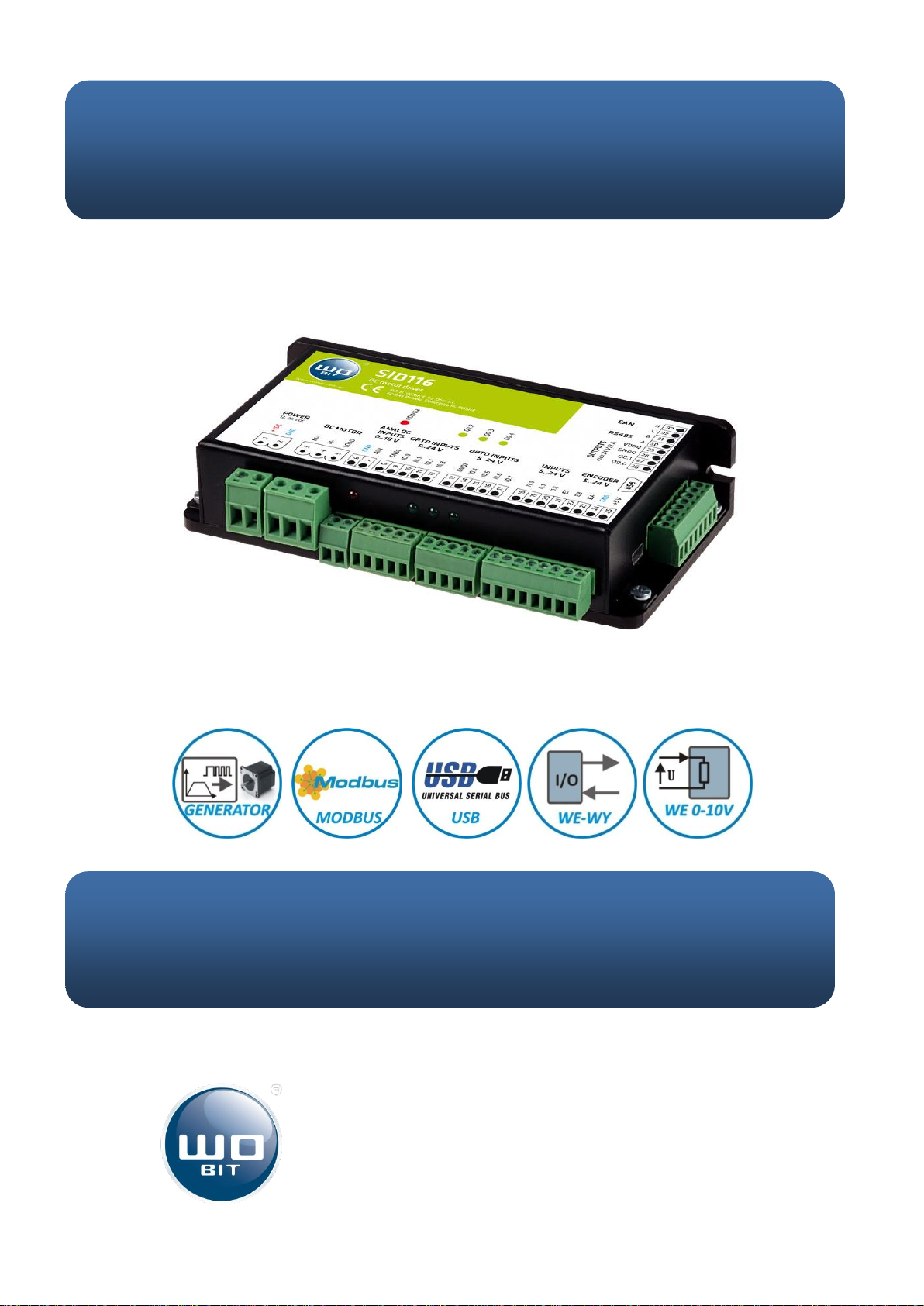
User manual SID116 –09.04.2015r. v.1.0
Contains
1. Safety and assembly rules.....................................................................................................................4
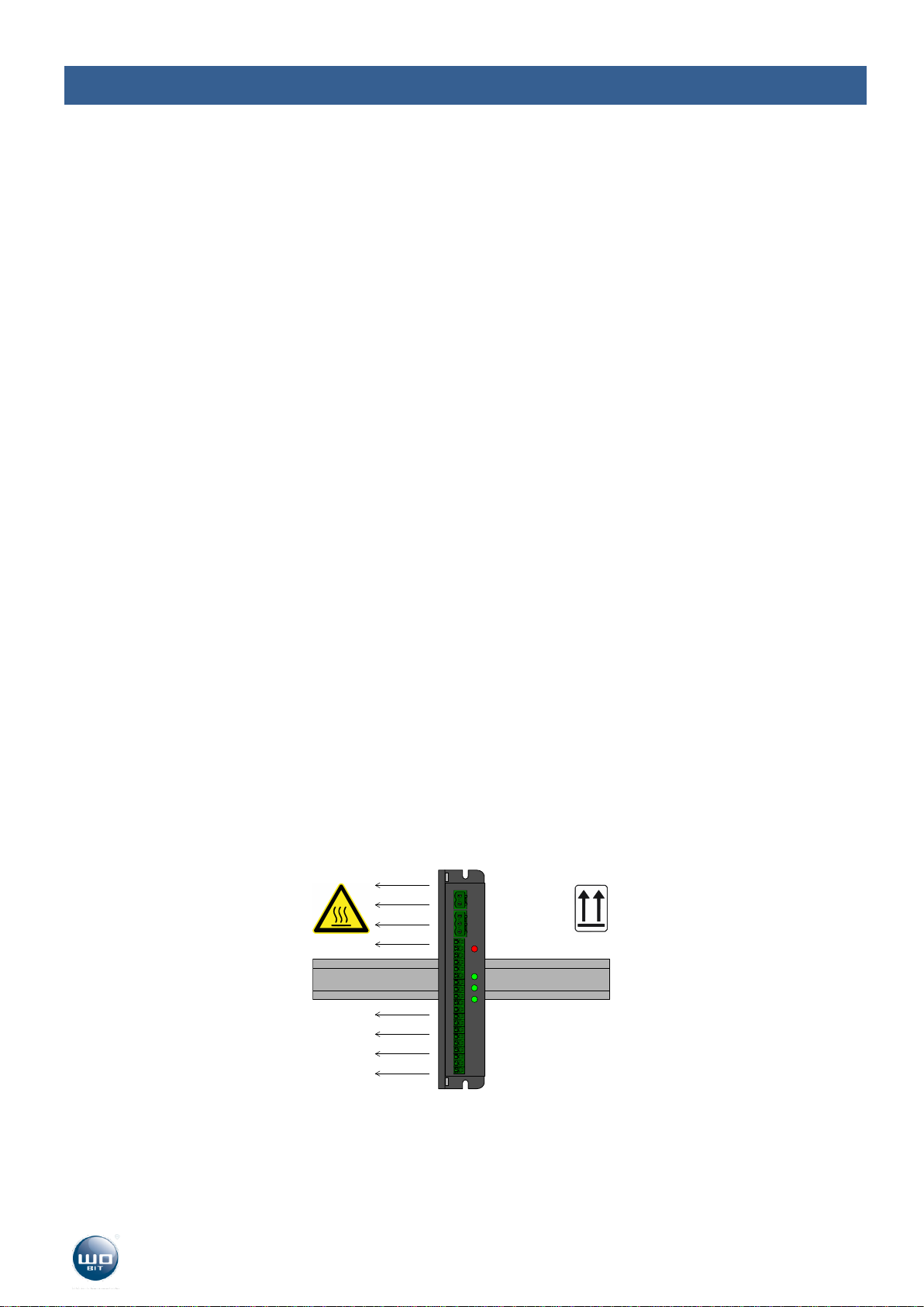
1.1 Safety rules ...................................................................................................................................................4
1.2 Assembly recommendation..........................................................................................................................4
2. Introduction .........................................................................................................................................5
2.1 Intended use.................................................................................................................................................5
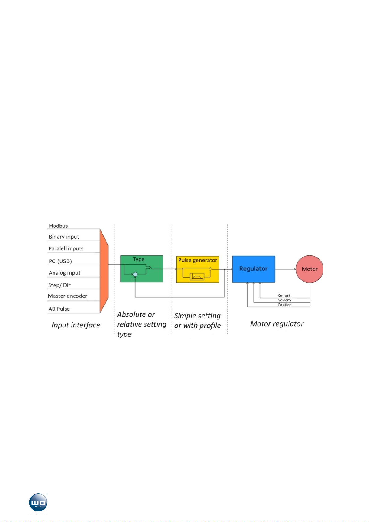
2.2 Functions ......................................................................................................................................................6
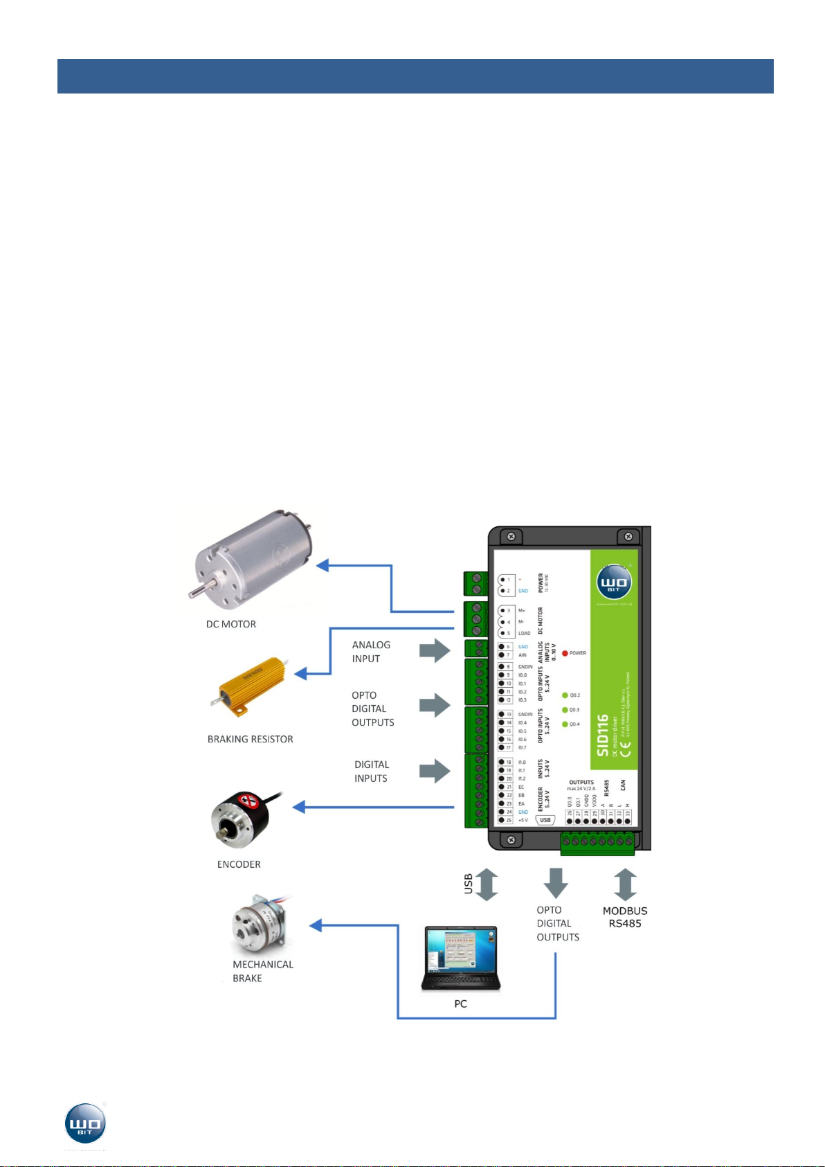
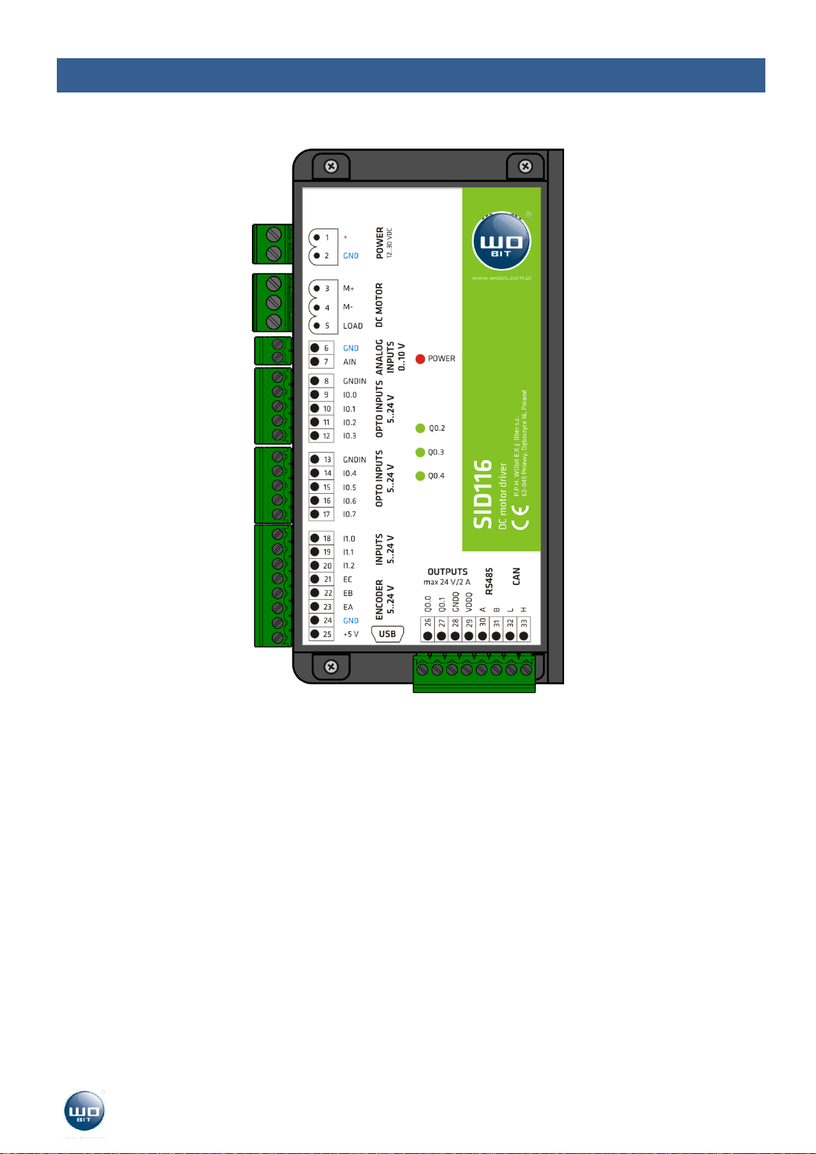
3. Device description ................................................................................................................................8
3.1 Connectors and indicators arrangement......................................................................................................8
3.2 Power supply ................................................................................................................................................9
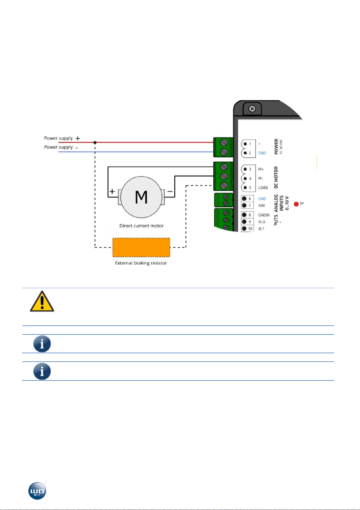
3.3 Motor and braking resistor.........................................................................................................................10
3.4 Incremental encoder ..................................................................................................................................11
3.5 Programmable inputs .................................................................................................................................12
3.6 Analog input ...............................................................................................................................................13
3.7 Programmable outputs...............................................................................................................................13
3.8 Control interfaces .......................................................................................................................................14
3.9 Communication interfaces .........................................................................................................................15
4. SID116 –PC software..........................................................................................................................16
4.1 USB connection with PC .............................................................................................................................16
4.2 Application interface description ...............................................................................................................16
5. Driver configuration............................................................................................................................25
5.1 Commissioning............................................................................................................................................25
5.2 Open loop operation (PWM mode)...........................................................................................................29
5.3 Regulator adjusting.....................................................................................................................................29
5.4 Current regulation ......................................................................................................................................31
5.5 Velocity regulation......................................................................................................................................32
5.6 Position regulator .......................................................................................................................................32
5.7 Dynamic braking (braking resistor).............................................................................................................34
5.8 Driver error handling. .................................................................................................................................36
6. MODBUS communication....................................................................................................................38
7. Record of changes...............................................................................................................................39
8. Technical parameters..........................................................................................................................40