WOBIT SMC50 User manual

P.P.H. WObit E.K.J. Ober s.c.
62-045 Pniewy, Dęborzyce 16
tel.+48 61 22 27 410, fax.+48 61 22 27 439
e-mail: wobit@wobit.com.pl
www.wobit.com.pl
SMC50 Manual
Miniature driver for stepper motors max. 0.75A

www.wobit.com.pl
Manual -SMC50 –27.10.2014 –v.1.1
page 2
Contains
1. Main characteristic of the driver......................................................................................................... 2
2. Connectors description: ...................................................................................................................... 3
3. Setting current phase .......................................................................................................................... 5
4. Setting division .................................................................................................................................... 6
5. Description of the controlling inputs.................................................................................................. 6
6. Power supply ....................................................................................................................................... 7
7. Connecting of the motor ..................................................................................................................... 7
8. Safety and installation rules ................................................................................................................ 8
9. Technical data.................................................................................................................................... 10
10. Kit assembly..................................................................................................................................... 10
Thank you for choosing our product!
This instruction will help you at correct service and accurate exploitation of described device.
Information included in this instruction were prepared with high attention by our specialists and is description of the
product. Based on the information should not be inferred a certain features or suitability for a particular application. This
information does not release the user from the obligation of own judgment and verification. P.P.H. WObit E.K.J. Ober s.c.
reserves the right to make changes without prior notice.
Please read instructions below carefully and adhere to its recommendation
Please pay special attention to the following characters:
CAUTION!
Not adhere to instruction can cause damage or impede the use of hardware or software.
1. Main characteristic of the driver
SMC50 is a driver designed for operation with 2-phase stepper motor. The driver provides controlling
by full step or by step divided into 2,4 or 8 parts, to extort proper current value in motor coiling,

www.wobit.com.pl
Manual -SMC50 –27.10.2014 –v.1.1
page 3
which is independent on driver power supply. Each square pulse appearing on step input causes in
motor jump by one step or microstep, depends on step division depth set in the driver by jumpers
(M1 and M2). Motor rated current is set by potentiometer, which is located on driver PCB. The
potentiometer enables change current phase of the driver in range from 0,15A to 0,75A. The driver
has a power supply indicator in the shape of red LED diode. SMC50 is available in two versions:
As a module adopted to pin in PCB (M),
As a drive on L-shape profile (B) with handle on mounting rail (35mm).
SMC50 driver is sell as a component for building a driving system and should be mounted according
to mounting rules of electrical devices. The user is responsible for providing the compliance with
norms of noise emission and electromagnetic compatibility (proper cable derivation, using shields
and ferrite ring).
Features:
Controlling interface STEP/DIRECTION,
Wide range of power supply +15V…+28V (30Vmax.),
Miniature dimensions (board 50,5x47,6mm height with elements 20mm),
High step frequency up to 500kHz,
Rated current max. 0.75A on phase,
Set current by miniature potentiometer on controller mainboard,
Microstep with division up to 1/8,
Thermal protection of power end,
Ant rupture protection,
Protection of power supply decline,
Connection controlling signals by double-breasted pin stripes, adapted for clamping 10pin
tape (IDC10 connector),
Aluminum profile L shaped (B) or module for plug in board (M).
2. Connectors description:

www.wobit.com.pl
Manual -SMC50 –27.10.2014 –v.1.1
page 4
SV3 connector :
1-4: V +power supply of 15-28 VDC range,
5-8: GND power supply mass
9-12: A beginning of coiling phase of the motor
13-16:/A end of coiling phase of the motor
17-20: B beginning of coiling phase of the motor
21-24:/B end of coiling phase of the motor
SV2 connector:
1,3,5,7,9 –controlling signal ground
2- M2 input setting depth of step division
4- M1 input setting depth of step division

www.wobit.com.pl
Manual -SMC50 –27.10.2014 –v.1.1
page 5
6- EN input permission for motion (Enable)
8- DIR input signal direction
10- CLK input signal step
SV1 connector –connector choice of active edge clock signal
1 and 2 connected by jumper –active falling edge
2 and 3 connected by jumper –active rising edge
3. Setting current phase
Current phase is set by miniature potentiometer R19 which is located on PCB of the driver. Current is
switched linear in range from 0.15A to 0.75A.

www.wobit.com.pl
Manual -SMC50 –27.10.2014 –v.1.1
page 6
4. Setting division
Step division is set by M1 and M2 inputs according to table below.
5. Description of the controlling inputs
On graphic below is shown illustrative way of controlling driver inputs. For generating controlling
signals you can use generator ( for example GEN2 manufactured by WObit), trajectory generator
providing programming of the motion trajectory (MI 1.3.2. manufactured by WObit), PLC driver with
proper output (enabling generate fast square pulses) or micro driver.

www.wobit.com.pl
Manual -SMC50 –27.10.2014 –v.1.1
page 7
6. Power supply
For supply the driver it should not be used regulated power supply, unless specially prepared for this
aim (adapted for operation with stepper motor drivers). It should be used non regulated power
supply, which has large electrolytic capacitors on inputs necessary for absorb energy generated by
motor.
You should put your attention for maximal voltage of power supply. Safe power supply is lower than
allowable maximum, because to power supply you have to add energy of motor at braking and short
pulses created as effect fast turn off a great inductive of motor coiling. So recommended power
supply is in range 15VDC up to 28VDC. To this voltage is added energy generated by motor (back
EMF) which can rise for the meantime value of the power supply.
At first connecting driver to power supply on one’s own it is recommended to use ammeter (the best
is with moving iron) to control current consumption. The control of rated current is available by
oscilloscope by implementing in phase measuring resistor with low resistance (for example 0.01 ohm
1% 2W). In view of channel 1 and channel 2 mass of oscilloscope it is not possible to use the second
channel at system after implementing measuring resistor ( the oscilloscope mass will not on device
mass).
7. Connecting of the motor
On the picture below is presented exemplary way of connecting 8 and 6-wire motors to the
controller. Colors of wires regards to 57BYG081 motor (8-wires) and 42BYG802U (6-wires). Each time
before connecting the motor should be acquaint oneself with correct color of the wires, which are

www.wobit.com.pl
Manual -SMC50 –27.10.2014 –v.1.1
page 8
determined by the manufacturer of the motor. Wire colors are mostly on motor’s label.
8. Safety and installation rules
1. Manipulating at mechanical parts of the machine (shafts, screws, rails) at turned on stepper motor
controllers is not allowed because it can be dangerous for health and life. It is caused that, especially
during setting and testing the machine stepper motor can accomplish non expected movements
caused for example interference from other units the machine or using tools (drills etc.).

www.wobit.com.pl
Manual -SMC50 –27.10.2014 –v.1.1
page 9
2. It is recommend to entwine the wires for motor in pairs. If generated noise creates problems or
wires for motor has to be longer, it is recommended to create shield by branding motor wires with
transmitting tape and connect it to mass. To reduce noises generated by supply wires it should be
used ferrite rings mounted on those wires.
3. As signal cables it can be used AWG14 cut up to 28 and for supplying AWG22 or bigger.
4. Signal wires should be move away from power supply line and motor wires for min. 10cm. At any
case it can’t be entwine together.
5. Regarding to the thermal factors (motor creates a lot of heat) it is recommended to install the
motor on aluminum plate, or on other part of the machine, which can take excess of a heat. At any
case is recommend to control motor temperature during first tests on the machine (max. motor
temperature 85C).
6. It is recommend to mount the controller as close to the motor as possible regarding to length of
the motor wires.
7. It is recommended to solder end of wires, especially of the motor (possibility of short circuit) or
after putting on them the spade tips to clamp it in device.
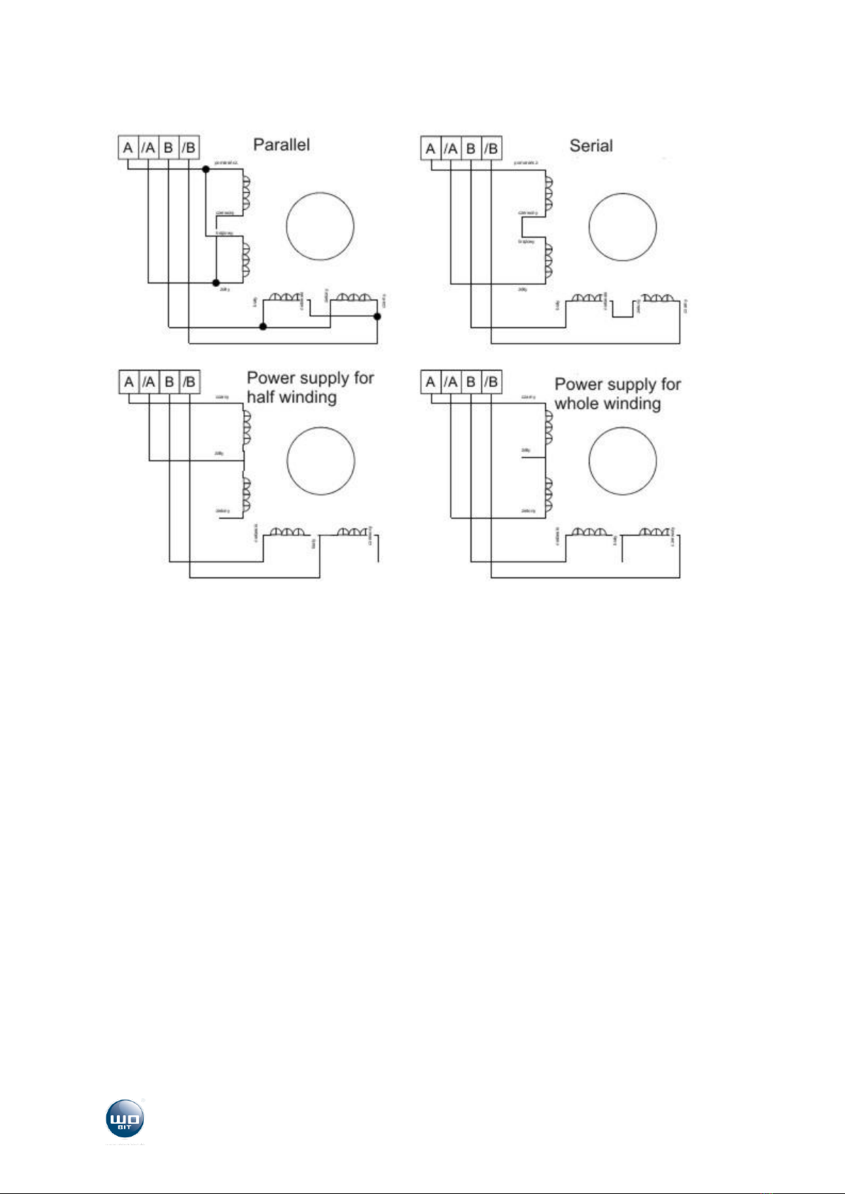
8. It is possible to make serial connection of bipolar windings (8-wires), when it is more important to
achieve rated torque, for example 1A winding controlled by rated current 1A or parallel by 2 bigger
current (about 1,4A for rated current of a half winding), when it is more important to achieve high
rotational speed of the motor (lower inductance of windings decides about faster rising the current
at winding). Nevertheless the temperature has to be controlled.
9. In case of transmitting power on different axle it is recommended to connect motor shafts and a
mechanism drives by clutch, specially adopted to this aim. It’s eliminate misalignment of installation
and prolong life time of motor bearings. This requirements very good fulfill Oldham clutches.
10. Do not screw, cut or drill motor shafts or its housing. Disassemble of the motor is possible only by
manufacturer, because after disassemble it the motor lose part of its torque as a result of
impairment of magnetic circuit. Disassemble of motor torque can also be caused by strong shocks
and vibrations.
11. To improve dynamic features can be used damper. Magnetic damper helps to reduce vibrations
and motor resonance and can enlarge maximal rotational speed even up to 2x.
12. Stepper motor is an electric device. Common rules regarding exploitation of electric devices are
binding. Before turn on of the controller, please make sure, that all moving parts of the machine or
motor itself will not interfere with other parts of the machine or will not hurt people.
13. Never connect supply cables of not discharged feeder (without load feeder can keep energy
accumulated in electrolytic capacitor for a long time). To discharge electrolytic capacitors is enough
to short-circuit low-impedance resistor clamp “+” with “-“ naturally at turn on power supply.

www.wobit.com.pl
Manual -SMC50 –27.10.2014 –v.1.1
page 10
9. Technical data
Electrical specification:
Power supply:
+15V..+28V (30V max.)
Phase current:
0,15..0,75A
Inputs:
3 (step, dir, disable)
Max. frequency of STEP signal:
500kHz
Resolution (motor 1,8):
200,400, 800, 1600 steps per
rotation
Power supply indicator:
red LED
Operating temperature:
0…+60C
Cooling version
gravitational
Recommended filling of STEP
signal
50%
Mechanical dimensions
50,5x47,5x22mm M version (plate
dimensions)
51x50x25mm B version
10. Kit assembly
Kit consist in :
SMC50 driver - 1pc.
Manual - 1pc.
Table of contents
Other WOBIT DC Drive manuals