Woelm HELM GT-L 80 User manual

Montageanleitung
Installation instructions
HELM GT-L 80
für Holztüren bis 80 kg
mit Einzugsdämpfung
einflügelig (mit Berechnungen)
Türstärken
von 30 - 50 mm
HELM GT-L 80
for timber doors up to 80 kg
with soft closing device
single leaf (with calculations)
Door thickness from
30 up to 50 mm
MA: DS020745/07.2017

2
SW 3 / 4 Nm
TX 30 / 17Nm
AF 3 / 4 Nm
TX 30 / 17Nm
Größe 2,5 / 3 / 4
Size 2,5 / 3 / 4
SW 8, 10, 13
AF 8, 10, 13
Technische Informationen
• maximales Flügelgewicht 80 kg
• Mindestflügelbreite bei der Verwendung der Einzugs-
dämpfung 700 mm
Benötigtes Werkzeug / Required tools
Technical information
• Maximum leaf weight 80 kg
• Minimum leaf width for use with soft closing
device 700 mm
DS020745/07.2017
HELM GT-L 80
Allgemeine Informationen / General information

3
min. 700
Lieferumfang
Scope of delivery
DS020745/07.2017
HELM GT-L 80
Allgemeine Informationen / General information
1. Laufschiene / Track
2. Blende / Pelmet
3. Abdeckkappen
4. Rollapparat / Trolley
5. Stopper links / End stop, left-hand side
6. Stopper rechts / End stop, right-hand side
7. Untere Führung / Bottom guide
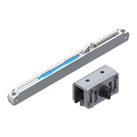
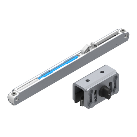
8. Einzugsdämpfer / Soft closing device
9. Auslösebolzen / Release bolt
10. Befestigungswinkel Rollapparat /
Mounting bracket trolley
11. Befestigungswinkel Auslösebolzen /
Mounting bracket release bolt

4
Türabstand bei Wandmontage
Door space with wall mount
Montage der Befestigungswinkel
Hinweis: Achten Sie bei der Montage auf das geeignete
Befestigungsmaterial.
Installation of mounting brackets:
Note: Please pay attention for the right mounting material.
Türabstand
Door space (TA)
TA = 23,75 – Y
Abstand Führung
Space lead (AF):
AF = (TD : 2) + TA
Legende:
TA = Türabstand
AF = Abstand Führung
Legend:
TA = Door space
AF = Space lead
DS020745/07.2017
HELM GT-L 80
Montage / Installation

5
Wandmontage
Wall mount
Deckenmontage
Ceiling mount
Bohrhöhe (BH)
Drilling height (BH):
BH = LH + X + 35
Türhöhe (TH)
Door heigth (TH):
TH = BH – 39 – 10
Türhöhe (TH)
Door height (TH):
TH = LH – 61 – 10
Wand-/Deckenmontage, bei durchlaufender Wand und verdecktem Muschelgriff
Wall/Ceiling mount, continuous wall with covered flush pull
1 Flügel
1 Panel
Bsp.: / Example: TH = 2157,00; GA1 = 80,00
LW = 950,00; GA2 = 60,00
Türbreite Schiebetür (TB)
Door width siding door (TB)
TB = LW + 50,00 + 30,00
Bsp.: / Example: TB = 950,00 + 50,00 + 30,00 = 1030,00
Laufschienenlänge (L) MG verdeckt
Track length (L) MG covered
L = TB + LW + 30,00
Bsp.: / Example: L = 1030,00 + 950,00 + 30,00 = 2010,00
Durchgangsbreite (DB) MG verdeckt
Walk-through distance (DB) MG covered
DB = LW
Bsp.: / Example: DB = 950,00
Legende:
LH = lichte Höhe
LW = lichte Weite
BH = Bohrhöhe
TH = Türhöhe
TB = Türbreite Schiebetür
MG = Muschelgriff
L = Laufschienenlänge
GA1 = Griffabstand 1
GA2 = Griffabstand 2
DB = Durchgangsbreite
Legend:
LH = Clear height
LW = Clear width
BH = Drill height
TH = Door height
TB = Door width (sliding door)
MG = Flush pull
L = Track length
GA1 = Handle distance 1
GA2 = Handle distance 2
DB = Walk through distance
DS020745/07.2017
HELM GT-L 80
Montage / Installation

6
1 Flügel
1Panel
Bsp.: / Example: TH = 2157,00; GA1 = 80,00
LW = 950,00; GA2 = 60,00
Türbreite Schiebetür (TB)/
Door width slinding door (TB)
TB = LW + 50,00 + 30,00
Bsp.: / Example: TB = 950,00 + 50,00 + 30,00 = 1030,00
Laufschienenlänge (L) MG halb verdeckt
Track length (L) Flush pull half covered
L = TB + LW - GA1
Bsp.: / Example: L = 1030,00 + 950,00 - 80,00 = 1900,00
Durchgangsbreite (DB) MG halb verdeckt
Walk-through distance (DB) MG half covered
DB = LW - GA1 - 30,00
Bsp.: / Example: DB = 950,00 - 80,00 - 30,00 = 840,00
Wand-/Deckenmontage bei durchlaufender Wand und halb verdecktem Muschelgriff
Wall/Ceiling mount, continuous wall with half covered flush pull
Wandmontage
Wall mount
Deckenmontage
Ceiling mount
Legende:
LH = lichte Höhe
LW = lichte Weite
BH = Bohrhöhe
TH = Türhöhe
TB = Türbreite Schiebetür
MG = Muschelgriff
L = Laufschienenlänge
GA1 = Griffabstand 1
GA2 = Griffabstand 2
DB = Durchgangsbreite
Legend:
LH = Clear height
LW = Clear width
BH = Drill height
TH = Door height
TB = Door width (sliding door)
MG = Flush pull
L = Track length
GA1 = Handle distance 1
GA2 = Handle distance 2
DB = Walk through distance
Bohrhöhe (BH)
Drilling height (BH):
BH = LH + X + 35
Türhöhe (TH)
Door heigth (TH):
TH = BH – 39 – 10
Türhöhe (TH)
Door height (TH):
TH = LH – 61 – 10
DS020745/07.2017
HELM GT-L 80
Montage / Installation

7
1 Flügel
1Panel
Bsp.: / Example: TH = 2157,00; GA1 = 80,00
LW = 950,00; GA2 = 60,00
Türbreite Schiebetür (TB)
Door width sliding door (TB)
TB = LW + 50,00 + 30,00
Bsp.: / Example: TB = 950,00 + 50,00 + 30,00 = 1030,00
Laufschienenlänge (L)
Track length (L)
L = TB + LW - GA1 - GA2
Bsp.: / Example: L = 1030,00 + 950,00 - 80,00 - 60,00 = 1840,00
Durchgangsbreite (DB)
Walk-through distance (DB):
DB = LW - GA1 - GA2 - 30,00
Bsp.: / Example: DB = 950,00 - 80,00 - 60,00 - 30,00 = 780,00
Wand-/Deckenmontage bei durchlaufender Wand und Stangengriff
Wall/Ceiling mount, continuous wall with door handle
Wandmontage
Wall mount
Deckenmontage
Ceiling mount
Legende:
LH = lichte Höhe
LW = lichte Weite
BH = Bohrhöhe
TH = Türhöhe
TB = Türbreite Schiebetür
MG = Muschelgriff
L = Laufschienenlänge
GA1 = Griffabstand 1
GA2 = Griffabstand 2
DB = Durchgangsbreite
Legend:
LH = Clear height
LW = Clear width
BH = Drill height
TH = Door height
TB = Door width (sliding door)
MG = Flush pull
L = Track length
GA1 = Handle distance 1
GA2 = Handle distance 2
DB = Walk through distance
Bohrhöhe (BH)
Drilling height (BH):
BH = LH + X + 35
Türhöhe (TH)
Door heigth (TH):
TH = BH – 39 – 10
Türhöhe (TH)
Door height (TH):
TH = LH – 61 – 10
DS020745/07.2017
HELM GT-L 80
Montage / Installation

8
1 Flügel
1 Panel
Bsp.: / Example: TH = 2157,00; GA1 = 80,00
LW = 950,00; GA2 = 60,00
Türbreite Schiebetür (TB)
Door width sliding door (TB)
TB = LW + 50,00 - 4,00
Bsp.: / Example: TB = 950,00 + 50,00 - 4,00 = 996,00
Laufschienenlänge (L) MG verdeckt
Track length (L) MG covered
L = TB + LW
Bsp.: / Example: L = 996,00 + 950,00 = 1946,00
Durchgangsbreite (DB) MG verdeckt
Walk-through distance (DB) MG covered
DB = LW
Bsp.: / Example: DB = 950,00
Wand-/Deckenmontage bei nicht durchlaufender Wand, mit verdecktem Muschelgriff
Wall/Ceiling mount without continuous wall, with covered flush pull
Wandmontage
Wall mount
Deckenmontage
Ceiling mount
Legende:
LH = lichte Höhe
LW = lichte Weite
BH = Bohrhöhe
TH = Türhöhe
TB = Türbreite Schiebetür
MG = Muschelgriff
L = Laufschienenlänge
GA1 = Griffabstand 1
GA2 = Griffabstand 2
DB = Durchgangsbreite
Legend:
LH = Clear height
LW = Clear width
BH = Drill height
TH = Door height
TB = Door width (sliding door)
MG = Flush pull
L = Track length
GA1 = Handle distance 1
GA2 = Handle distance 2
DB = Walk through distance
Bohrhöhe (BH)
Drilling height (BH):
BH = LH + X + 35
Türhöhe (TH)
Door heigth (TH):
TH = BH – 39 – 10
Türhöhe (TH)
Door height (TH):
TH = LH – 61 – 10
DS020745/07.2017
HELM GT-L 80
Montage / Installation

9
1 Flügel
1 Panel
Bsp.: / Example: TH = 2157,00; GA1 = 80,00
LW = 950,00; GA2 = 60,00
Türbreite Schiebetür (TB)
Door width sliding door (TB)
TB = LW + 50,00 - 4,00
Bsp.: / Example: TB = 950,00 + 50,00 - 4,00 = 996,00
Laufschienenlänge (L) MG halb verdeckt
Track length (L) MG half covered
L = TB + LW - GA1 + 4,00
Bsp.: / Example: L = 996,00 + 950,00 - 80,00 + 4,00 = 1870,00
Durchgangsbreite (DB) MG halb verdeckt
Walk-through distance (DB) MG half covered
DB = LW - GA1 + 4,00
Bsp.: / Example: DB = 950,00 - 80,00 + 4,00 = 874,00
Wand-/Deckenmontage bei nicht durchlaufender Wand, mit halb verdecktem Muschelgriff
Wall/Ceiling mount without continuous wall, with half covered flush pull
Wandmontage
Wall mount
Deckenmontage
Ceiling mount
Legende:
LH = lichte Höhe
LW = lichte Weite
BH = Bohrhöhe
TH = Türhöhe
TB = Türbreite Schiebetür
MG = Muschelgriff
L = Laufschienenlänge
GA1 = Griffabstand 1
GA2 = Griffabstand 2
DB = Durchgangsbreite
Legend:
LH = Clear height
LW = Clear width
BH = Drill height
TH = Door height
TB = Door width (sliding door)
MG = Flush pull
L = Track length
GA1 = Handle distance 1
GA2 = Handle distance 2
DB = Walk through distance
Bohrhöhe (BH)
Drilling height (BH):
BH = LH + X + 35
Türhöhe (TH)
Door heigth (TH):
TH = BH – 39 – 10
Türhöhe (TH)
Door height (TH):
TH = LH – 61 – 10
DS020745/07.2017
HELM GT-L 80
Montage / Installation

10
1 Flügel
1 Panel
Bsp.: / Example: TH = 2157,00; GA1 = 80,00
LW = 950,00; GA2 = 60,00
Türbreite Schiebetür (TB)
Door width sliding door (TB)
TB = LW + 50,00 - 4,00
Bsp.: / Example: TB = 950,00 + 50,00 - 4,00 = 996,00
Laufschienenlänge (L)
Track length (L)
L = TB + LW - GA1 - GA2 + 4,00
Bsp.: / Example: L = 996,00 + 950,00 - 80,00 - 60,00 + 4,00 = 1810,00
Durchgangsbreite (DB)
Walk-through distance (DB)
DB = LW - GA1 - GA2 + 4,00
Bsp.: / Example: DB = 950,00 - 80,00 - 60,00 + 4,00 = 814,00
Wand-/Deckenmontage bei nicht durchlaufender Wand, mit Stangengriff
Ceiling mount without continuous wall, with door handle
Wandmontage
Wall mount
Deckenmontage
Ceiling mount
Legende:
LH = lichte Höhe
LW = lichte Weite
BH = Bohrhöhe
TH = Türhöhe
TB = Türbreite Schiebetür
MG = Muschelgriff
L = Laufschienenlänge
GA1 = Griffabstand 1
GA2 = Griffabstand 2
DB = Durchgangsbreite
Legend:
LH = Clear height
LW = Clear width
BH = Drill height
TH = Door height
TB = Door width (sliding door)
MG = Flush pull
L = Track length
GA1 = Handle distance 1
GA2 = Handle distance 2
DB = Walk through distance
Bohrhöhe (BH)
Drilling height (BH):
BH = LH + X + 35
Türhöhe (TH)
Door heigth (TH):
TH = BH – 39 – 10
Türhöhe (TH)
Door height (TH):
TH = LH – 61 – 10
DS020745/07.2017
HELM GT-L 80
Montage / Installation

11
Montage
Installation
Die Stopper stirnseitig in die Laufschiene einschieben und am jeweiligen Schienenende grob positionieren, ohne eine Befestigungsbohrung zu
verdecken.
Slide stoppers into track and position in desired location without covering any fixing bore holes.
Die Klemmadapter (zwei Stück pro Meter) und Einzugsdämpfer wie dargestellt in die Laufschiene einschieben.
Slide clamp adapters (two per meter) and dampers into the track.
1
2
Größe 2,5
Size 2,5
Größe 2,5 / 3
Size 2,5 / 3
DS020745/07.2017
HELM GT-L 80
Montage / Installation
12
Montage
Installation
4
3Die Laufschiene waagerecht und lotrecht an die Wand bzw. Decke montieren.
Wichtig: Nur Befestigungsmaterial verwenden, das für den vorhandenen Untergrund geeignet ist.
Install track level either onto wall or ceiling.
NOTE: Fix track only with suitable load bearing materials (stud or solid wood blocking).
SW 8
SW 8
5
Die Sechskantschrauben (1) aus der oberen Position (Pos. 1)
lösen in die untere Position (Pos. 2) versetzten.
Solve the hexagon bolts (1) from the upper position (Pos. 1) and
move them into the lower position (Pos. 2).
DS020745/07.2017
HELM GT-L 80
Montage / Installation
Für die Verwendung der Befestigungswinkel müssen die Klemm-
einlagen im Rollapparat und Auslösebolzen, wie in nebenstehender
Abbildung dargestellt, eingesetzt werden.
Clamping inserts of trolley and release bolt for use with the
mounting brackets, have to be adjusted like shown in the left
figure.

13
Die Sicherungsschrauben (1) durch die mitgelieferten Sechskantschrauben M6 x 45 ersetzen und soweit eindrehen, bis diese bündig mit der Klemm-
platte sind.
Replace the lower safety screws (1) with provided hexagonal screws M6 x 45 and lower the safety screws until they are flush with clamping device.
6
Die Befestigungswinkel jeweils 45 mm von der Stirnseite des Flügels positionieren und festschrauben. Die Rollapparate ganz auf die Befestigungs-
winkel aufschieben, die schwarzen Schutzgummis müssen kopfseitig an den Winkeln anliegen und bündig mit der Stirnseite vom
Winkel positioniert sein. Anschließend die Rollapparate auf die Winkel mit einem Anzugsmoment von 17 Nm klemmen, hierfür einen Drehmoment-
schlüssel mit Torx-Aufsatz (TX30) verwenden. Den Auslösebolzen mittig auf das Türblatt
schieben und mit 4 Nm festziehen.
Position
each of the
mounting brackets 45 mm from the front side of the door leaf.
Push the trolley onto the mounting brackets until the protective
rubber pushes against the top of the bracket
and position flush with the front side of the mounting brackets.
Tighten trolleys with a torque of 17 Nm
and use a torque wrench with Torx bit (TX30).
Center the release bolt on the door leaf and tighten it with 4 Nm.
7
Größe / Size 3SW 10
Montage
Installation
SW 3 / 4 Nm
AF 3 / 4 Nm
TX 30 / 17 Nm
TX 30 / 17 Nm
DS020745/07.2017
HELM GT-L 80
Montage / Installation

14
Mit einem Lot die Position der unteren Führung ermitteln. Bohr-
bild übertragen, bohren und die untere Führung befestigen.
Use a plumb bob to determine the position of the bottom guide.
Transfer drilling pattern, drill and fix the bottom guide.
8
Montage
Installation
DS020745/07.2017
HELM GT-L 80
Montage / Installation
15
Größe 2,5 / 4
Size 2,5 / 4
SW/AF 10 / 13
9
Den Auslösebolzen mittels Einstellplatte in der Höhe so einstellen, dass der Auslösebolzen in der Fanggabel vom Einzugsdämpfer greift und bei Betäti-
gung diesen spannt.
Adjust actuator in height via setting plate. The actuator has to fit in the tappet and stretches the damper.
10
Wichtig: Die Laufflächen der Schiene und die Rollen vor
dem Einsetzen des Türblattes säubern. Die Rollapparate
sind mit wartungsfreien Kugellagern ausgestattet und
dürfen nicht nachgefettet werden.
Das Türblatt in die Laufschiene hängen und über die Exzenterschrau-
ben (1) mit Hilfe einer Wasserwaage ausrichten. Anschließend die
Exzenterschraube (1) über die Kontermuttern fixieren. Die Siche-
rungsschrauben soweit hoch drehen, bis ein leichter Kontakt zur
Laufschiene besteht, dann diese wieder um eine ½ Umdrehung
zurück drehen.
Wichtig: Die Sicherungsschrauben verhindern das Aushe-
ben der Tür bei unsachgemäßer Betätigung.
Die Stopper in der Laufschiene am jeweiligen Schienenende so posi-
tionieren, dass die gewünschte Türöffnung freigegeben wird und wie
folgt klemmen: zuerst die obere Schraube (5a) des Stoppers anzie-
hen, bis sich das Bauteil in der Schiene gesetzt hat. Nun die untere
Schraube (5b) leicht anziehen. Anschließend beide Schrauben eine
¼ Umdrehung nachziehen.
Important: Clean running surface before inserting door.
All trolleys are equipped with maintenance free bearings
and should not be greased.
Position the door pane in the track and align using the eccentric
screws (1) and a level. Then tighten the eccentric screws (1) using the
counter nuts. Turn the locking screws until they are in light contact
with the track, then turn them back again by a ½ turn.
Important: The locking screws serve as the anti-jump sys-
tem and prevent the door from jumping if improperly
used.
Position the trolley stops in the track at the respective end of the
track so that the required door opening is achieved and clamp as
follows: screw the top screw (5a) on the stopper until the component
has set in the track. Now tighten the bottom screw (5b) slightly. Then
retighten both screws by turning them a additional ¼ turn.
Montage
Installation
SW/AF 8
DS020745/07.2017
HELM GT-L 80
Montage / Installation

16
Montage
Installation
Größe / Size 3
Größe / Size 3
12 Die Klemmadapter wie dargestellt an der Laufschiene verteilen und fixieren.
Spread the clamp adapters on the track and fix them.
11 Das Türblatt mit dem Auslösebolzen in den rechten gelösten Einzugsdämpfer wie dargestellt einschieben. Türe mit dem Einzugsdämpfer gegen den
rechten Stopper schieben und die Befestigungsschrauben vom Einzugsdämpfer festziehen. Den Vorgang für den linken Einzugsdämpfer wiederholen.
Slide the door with the actuator into the right non-attached damper. Slide the door with the damper to the right end-stop and tighten the damper
screws. Repeat those steps on the other side for the left damper.
DS020745/07.2017
HELM GT-L 80
Montage / Installation

17
Blende nach Abbildung unten an den Klemmadaptern ansetzen
und an der oberen Klemmstelle andrücken.
Place pelmet at the bottom part of the clamp adapter and clip-on
at the top.
13
Montage
Installation
14 Bei Verwendung der optionalen Abdeckkappen:
Die Stirnseiten der Profile mit z.B. UV-Spezialreiniger oder Aceton reinigen, anschließend die optionalen Abdeckkappen seitlich auf die Blende
kleben.
(Zubehör siehe Katalog TDH_02G)
When using the optional end caps:
Clean the end faces of the pelmet, e.g. with white spirits or acetone, then glue the caps onto the side of the pelmet.
(Accessories can be found in Catalogoue TEH_02G)
DS020745/07.2017
HELM GT-L 80
Montage / Installation

18
Um Verletzungsgefahren zu minimieren sind folgende Maßnahmen bei Betrieb und Wartung von Ganzglaselementen zu beachten:
• Sitz und Gängigkeit der Beschläge überprüfen und Justierung der Tür regelmäßig kontrollieren. Notwendige Einstellungen sind durch eine Fachfirma
durchzuführen
• Glastüren und Glaselemente die Beschädigungen aufweisen (z. B. Kantenverletzungen, muschelförmige Ausbrüche und Kratzer) sind abzusperren
und auszutauschen
• Der Kontakt zwischen Glas und Metall ist zu vermeiden, dies umfasst auch die Wahl von Montagehilfen
• Verschmutzungen sollten von den Laufflächen der Laufschiene regelmäßig entfernt werden
• Bei der Reinigung der Glasscheibe ist der Einsatz von mechanischen Reinigungsklingen zu vermeiden (um einer Beschädigung des Glases
vorzubeugen)
To minimise the risk of injury, comply with the following measures during operation and maintenance of all-glass elements:
• Regularly check the fit and smooth engagement of the panes and the adjustment of the door. Have a specialist company make any necessary
adjustments
• Cordon off and replace glass doors and glass elements that exhibit damages (e.g. edge damages, shell-shaped chips or scratches)
• Prevent contact between glass and metal; this also includes the selection of installation aids
• Regularly remove soiling from the track rail running faces
• When cleaning the glass pane, avoid the use of mechanical cleaning blades (to prevent damage of the glass)
Bei der alltäglichen Verwendung beugen diese Punkte einer Beschädigung der Glastür und den Beschlägen vor:
• Das Schiebeelement nicht verkeilen
• Handbetätigte Schiebeelemente nur an den hierfür vorgesehenen Türgriffen und Türdrückern öffnen und schließen
• Handbetätigte Schiebeelemente nicht zuwerfen und nicht stoßen, sondern langsam in die gewünschte Position führen
• Wenn die Leichtgängigkeit des Schiebelements nicht mehr gegeben ist, nach Ursachen suchen und diese beseitigen. Keine Gewalt anwenden!
During daily use, these points prevent damage to the glass door and the fittings:
• Do not wedge-in the sliding element
• Open and close hand-operated sliding elements using only the intended door handles and door openers
• Do not slam and shove hand-operated sliding elements; slowly guide them into the desired position
• If a pane is no longer easy to move, find the cause and repair it. Do not use force!
Pflege
Care
Die Reinigung von eloxiertem Aluminium darf nicht mit Säuren oder anderen alkalischen Reinigern erfolgen. Weiterhin sollten zur Reinigung keine Scheuer-
mittel und auch keine Stahlwolle verwendet werden. Staub, Flecken und leichte Verschmutzungen lassen sich mit lauwarmem Wasser entfernen.
Hartnäckige Schmutzstellen, wie Gips- oder Zementreste, lösen sich leicht, wenn Sie einige Spritzer eines herkömmlichen Netzmittels (z.B. Geschirrspül-
mittel) ins Wasser geben. Ein kleiner Spritzer vom Netzmittel reicht aus, um gute Ergebnisse bei der Reinigung zu erzielen. Wir weisen ausdrücklich darauf
hin, dass die Eloxalschicht mit Mörtel oder Kalkwasser beschädigt werden kann. Es ist also wichtig, dass der Eimer mit Wasser absolut keine anderen Stoffe
enthält, außer einem Netzmittel.
Do not clean anodised aluminium with acids or other alkaline cleaners. Furthermore, scouring powder and steel wool should not be used for cleaning. Dust,
stains and light soiling can be removed with lukewarm water. Stubborn soiling such as gypsum or cement remnants can be easily removed if you add a few
squirts of a conventional wetting agent (like dish washing liquid) to the water. A small squirt of a wetting agent is sufficient to obtain good results during
cleaning. We explicitly point out that the anodised coating can be damaged by mortar and lime water. That means it is important that the bucket with
water does not contain any substances other than a wetting agent.
Wartung
Maintenance
Bestimmungsgemäße Verwendung
Intended use
DS020745/07.2017
HELM GT-L 80
Pflege- und Wartungshinweise / Service notes


Die technischen Angaben entsprechen dem neusten
Stand. Änderungen in Konstruktion und Formgestal-
tung, die dem Fortschritt dienen, behalten wir uns
vor. Wir bitten um Verständnis, dass für Druckfehler
oder Irrtümer keine Haftung übernommen werden
kann. Der Nachdruck ist, auch auszugsweise, ohne
unsere ausdrückliche Genehmigung nicht gestattet.
Art.-Nr.: DS020745/07.2017
Hiermit werden alle früheren Montageanleitungen
ungültig.
Woelm GmbH
Hasselbecker Str. 2-4
D-42579 Heiligenhaus
Tel.: + 49 (0) 20 56 - 18 - 0
Fax: + 49 (0) 20 56 - 18 - 21
www.woelm.de
Woelm Austria GmbH
Seewalchen 5a
A-5201 Seekirchen
Tel.: + 43 (0) 62 12 - 25 02
Fax: + 43 (0) 62 12 - 69 95
www.woelm.at
The technical specifications are up-to-date. We reserve
the right to make modifications with regard to design
and styling which serve the purpose of technical
improvement. We appreciate your understanding
that we assume no liability for any typing errors or
any other errors. The reproduction of this document,
in extracts or complete, is not permitted without our
express written permission.
Part no.: DS020745/07.2017
This installation instructions supersedes all
previous installation instructions.
Other manuals for HELM GT-L 80
1
Table of contents
Other Woelm Door Opening System manuals
Popular Door Opening System manuals by other brands

DITEC
DITEC DOD Series Installation & maintenance manual

Assa Abloy
Assa Abloy Norton SafeZone 7100SZ Series Installation and instruction manual

MOTION4
MOTION4 EvoDrive+ installation manual

Assa Abloy
Assa Abloy DC3210 Series installation instructions

PDQ
PDQ DOOR CLOSER instruction sheet

Von Duprin
Von Duprin 33A Series installation instructions

ECO Schulte
ECO Schulte FH842 Assembly instructions

EZ-ACCESS
EZ-ACCESS CONCIERGE 23DL installation manual

MS Sedco
MS Sedco ID20 installation instructions

Aumuller
Aumuller FTA600 R Assembly and commissioning instructions

Von Duprin
Von Duprin 98/9975 Series installation instructions

Dorma
Dorma 8900 PT manual