8
DS032050/01.2018
1 Flügel
1 Panel
Bsp.: TH = 2157,00; GA1 = 80,00
LW = 950,00; GA2 = 60,00
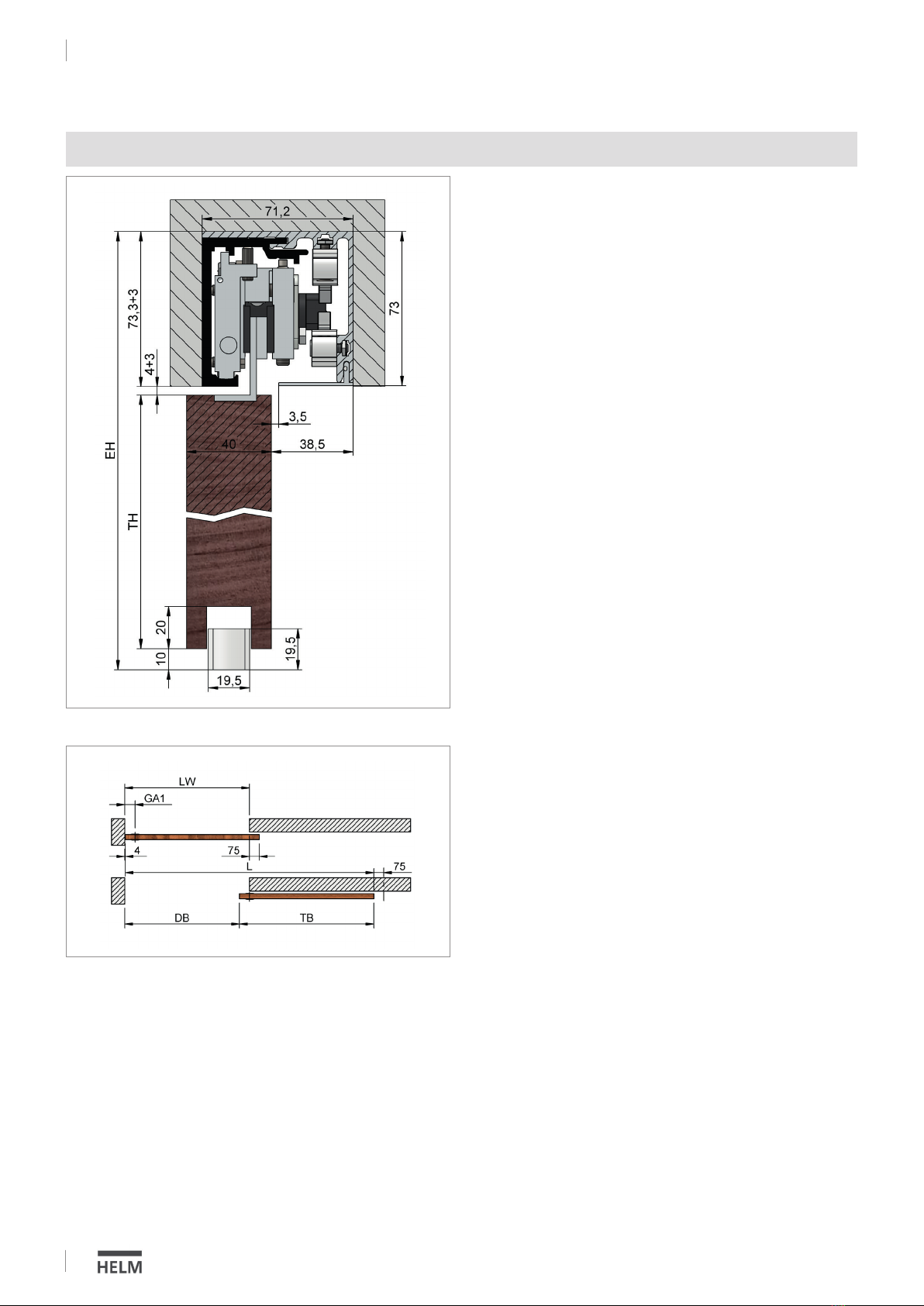
Türbreite Schiebetür (TB)
Door width sliding door (TB)
TB = LW + 75,00 - 4,00
Bsp.: TB = 950,00 + 75,00 - 4,00 = 1021,00
Laufschienenlänge (L) MG halb verdeckt
Track length (L) MG half covered
L = TB + LW - GA1 + 4,00 + 75,00
Bsp.: L = 1021,00 + 950,00 - 80,00 + 4,00 + 75,00 = 1970,00
Durchgangsbreite (DB) MG halb verdeckt
Walk-through distance (DB) MG half covered
DB = LW - GA1 + 4,00
Bsp.: DB = 950,00 - 80,00 + 4,00 = 874,00
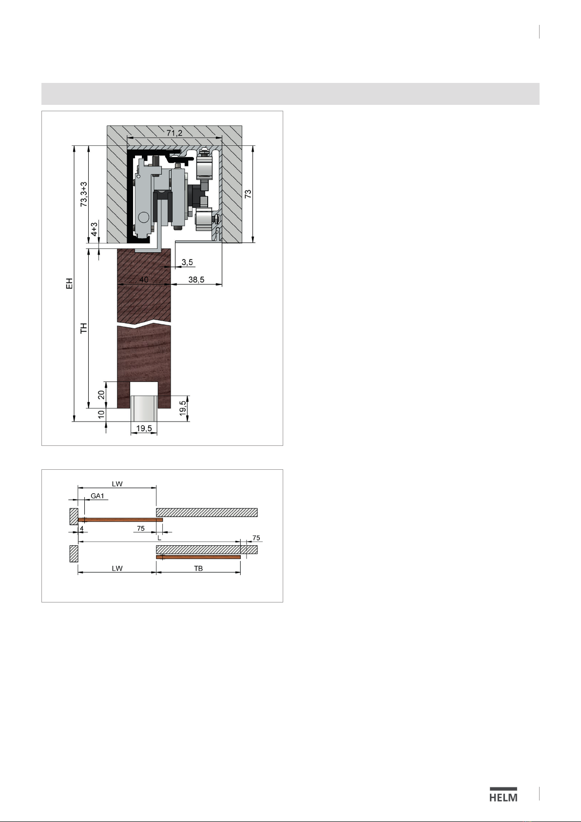
Legende:
LH = lichte Höhe
LW = lichte Weite
BH = Bohrhöhe
TH = Türhöhe
TB = Türbreite Schiebetür
MG = Muschelgriff
L = Laufschienenlänge
GA1 = Griffabstand 1
GA2 = Griffabstand 2
DB = Durchgangsbreite
Key:
LH = Clear height
LW = Clear width
BH = Drill height
TH = Door height
TB = Door width (sliding door)
MG = Flush pull
L = Track length
GA1 = Handle distance 1
GA2 = Handle distance 2
DB = Walk through distance
Türhöhe (TH) /
Door heigth (TH)
TH = EH – 77,3 - 10
Wand-/Deckenmontage bei nicht durchlaufender Wand, mit halb verdecktem Muschelgriff
Wall/Ceiling mount without continuous wall, with half covered flush pull
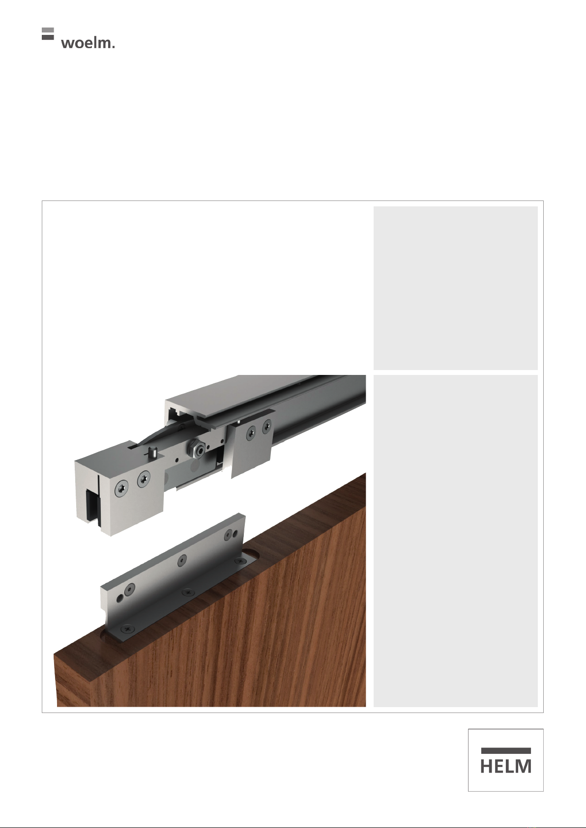
HELM GT-S 150
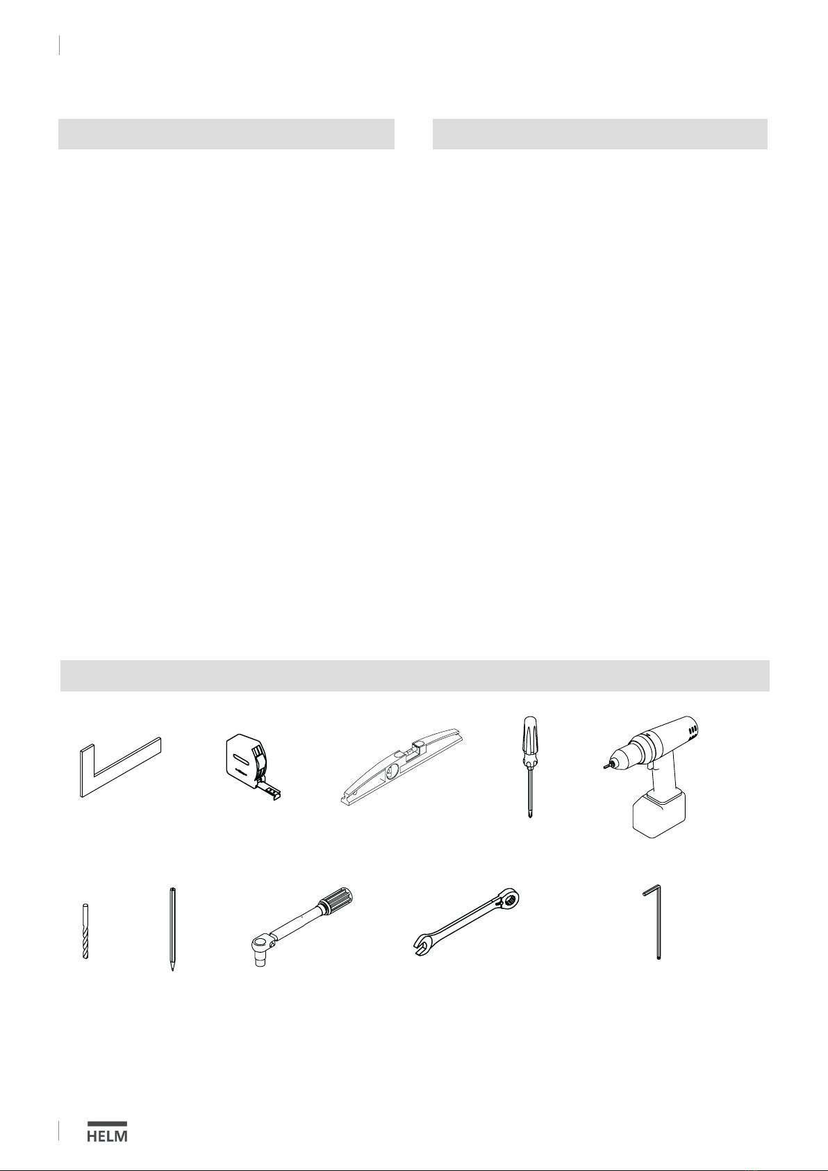
Montage / Installation