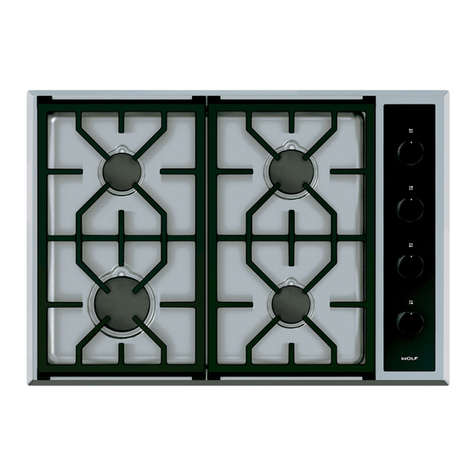
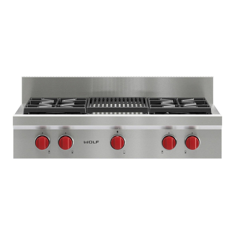
Wolf CG Series User manual

SERVICE MANUAL INTRODUCTION
This service manual assists with troubleshooting and
diagnosing malfunctions, completion of repairs, and return of
the product to proper operational condition. Read the complete
instructions contained within before initiating any repairs.
This guide is intended for use by Factory Certified Service. Wolf
Appliance, Inc. recommends that repairs be performed by
Factory Certified Service companies only.
Warning and Caution product safety labels appear throughout
this manual. Product safety labels appear at the beginning of
some sections. Follow the instructions in the product safety
labels to avoid personal injury and/or product damage. The
sample safety labels explain the types of notices that appear in
this manual.
WARNING
States a hazard that may cause serious injury or
death if precautions are not followed.
CAUTION
Indicates minor injury or product damage may occur
if instructions are not followed.
IMPORTANT NOTE: Highlights especially important information.
TIP: Indicates additional, useful information.
Information and images contained herein are copyright of Wolf
Appliance, Inc. Neither this manual nor any information or
images contained herein may be copied or used in whole or in
part without the express written consent of Wolf Appliance, Inc.
©Wolf Appliance, Inc., all rights reserved.
WOLF PRODUCT RATING PLATE INFORMATION
For CG Gas Cooktops, the product rating plate is located below
the burners.
Product
Rating
Plate
Important information for each product is listed on the product
rating plate. Rating plates identify:
▪Model
▪Serial number
▪Electrical information, including current draw
▪Burner heat ratings (in Btu)
▪Type and pressure of gas
MODEL DESCRIPTIONS AND SALES ACCESSORIES
For more details on individual model descriptions and a listing
of all compatible sales accessories, see the
Wolf Distributor
Price List
.
CG Series Gas Cooktops Service Manual
General Information
GENERAL INFORMATION
service.subzero.com
824779 REV. C 1

CG SERIES GAS COOKTOPS MODEL KEY
Model Character Description
ICB International Designation
C Product: Cooktop
G Type: Gas
15, 24, 30, or 36 Size (in Inches)
2, 3, 4, or 5 Number of Burners
C Style: Contemporary
P Style: Professional
T Style: Transitional
F Installation: Paired-Frame
S Finish: Classic Stainless Steel
LP Fuel: Liquid Propane (Natural Gas if Not Present)
PRODUCT USE AND CARE AND INSTALLATION GUIDES
Product Use and Care Guides, Installation Guides, and other
product specifications are available in the
Product
Specifications and Manuals Library
.
UNIT WARRANTY
Product warranty is determined by the installation location and
the date of installation.
▪View product warranties at
http://service.subzero.com/
ClaimsAndOrderProcessing/Pages/WarrantyInfo
.
▪Warranties start on the day of product installation.
▪Search for warranty and service information by serial
number, customer last name, and address using Unit
History at
http://service.subzero.com/Tools/UnitHistory
.
CG Series Gas Cooktops Service Manual
General Information
service.subzero.com
824779 REV. C 2

COMPONENT REMOVAL AND INSTALLATION
CG Series Gas Cooktops Service Manual
Component Removal and Installation
service.subzero.com
824779 REV. C 3

TROUBLESHOOTING GUIDE
CG Series Gas Cooktops Service Manual
Troubleshooting Guide
service.subzero.com
824779 REV. C 4

TROUBLESHOOTING GUIDE
Problem Possible Cause Test/Action
Constant sparking at surface
burner
Reverse polarity on outlet or unit (all burners) Test the polarity of the outlet. May have to call an
electrician. Check internal connections.
Ground wire disconnected or loose at outlet or
inside unit (all burners)
Check ground from unit to the ground terminal on
another outlet. May have to call an electrician.
Check internal connections.
Dirty igniter Clean with wire brush or emery cloth.
Cracked or damaged igniter Replace igniter.
Spark module(s) wired incorrectly or defective
(single burner) Re-wire or replace spark module(s)
Igniter not positioned properly (single burner) Reposition igniter. Igniter should be seated down
to burner pan.
Defective microswitch at burner valve (single
burner) Replace microswitch.
Cut or splice in igniter wire (single burner) Replace igniter wire.
Intermittent sparking at surface
burner
Dirty igniter Clean with wire brush or emery cloth.
Cracked or damaged igniter Replace igniter.
Cut or splice in igniter wire Replace igniter wire.
Bad wire connection at spark module Repair wire connection.
Defective spark module Replace spark module
Poor ignition at surface burner(s)
Igniter not positioned properly (single burner) Reposition igniter. Igniter should be seated down
to burner pan.
Partially-plugged ports in burner assembly Clear/clean as necessary.
Improper gas orifice Check orifice stamp number.
Gas pressure Check gas pressure with a manometer.
Improper gas type Check for gas type. Advise owner if improper. May
have to convert the unit to LP/natural gas.
Defective microswitch at burner valve Replace microswitch.
Defective/dirty igniter Replace/clean igniter.
Defective or loose wiring Replace/repair wiring.
Defective spark module(s) Replace spark module(s).
No spark at burner assembly or
assemblies
No power (all burners) Check outlet and circuit breaker.
Igniter wire disconnected or damaged. Replace igniter wire.
Loose or damaged wire to spark module Reconnect wire, or repair wire harness.
Defective 1-point spark module Replace 1-point spark module.
Popping noise at burner
assembly during simmer mode
Burner assembly damaged or dirty with food
debris Replace/clean burner assembly.
Burner assembly cracked or warped Replace burner assembly.
Supply gas impurities Especially common with LP gas
Flame appearance on burner
assembly or assemblies
▪Tall flame
▪Yellow flame
▪Pulsing flames
Port holes in burner assembly not to specification
or damaged/dirty Replace/clean burner assembly.
Incorrect gas orifices Check stamp number on orifices.
Gas pressure Check gas pressure using a manometer.
Secondary gas regulator within 10 feet of unit
regulator
Secondary regulator and unit regulator should be
at least 10 feet apart.
Unit regulator damaged Check gas pressure with manometer.
No knob or lighted knob display All light displays are dim Issue with neutral side of light circuit.
CG Series Gas Cooktops Service Manual
service.subzero.com
824779 REV. C 5

Problem Possible Cause Test/Action
No display lights check voltage to display light board.
No knob or lighted knob display No light in bezel
1Check voltage to bezel.
2Check the electrical connection.
3Replace the bezel.
REMOVE THE GAS VALVE BYPASS SCREW ORIFICE
Each gas valve has two bypass screw orifices installed on the
valve body. On sealed burners, this bypass screw is not
adjustable. If there is concern that the wrong bypass screw has
been installed into a gas valve, the size of the bypass screw can
be confirmed by comparing the number stamped on the bypass
screw to the
orifice chart
.
GAS PRESSURE TESTING
Testing gas supply pressure to a unit is a critical tool in properly
diagnosing a problem. Gas supply pressure issues are
common, and many times they are the root cause of recurring
issues. On CG units, each burner has an individual spark
module. There are no fuel-to-air ratio adjustments. Intermittent
sparking issues, flame quality issues, and ignition issues that
affect all burners are almost always related to gas pressure or
the supply regulator. Also, because there are three different
sizes of burner assemblies on each unit, pressure issues can
affect different sized burners in different ways. Gas pressure
must be checked by the method listed. The reason for this is so
that recorded pressures can be used to diagnose a specific
issue.
Natural Gas Specifications
The supply pressure to the inlet of the unit regulator must be
between a minimum of 7” water column (WC) and a maximum
of 14” WC.
The outlet of the regulator must be 5” - 5.5" WC.
The maximum pressure drop from maximum flow to low flow
must be less than .5” WC.
Liquid Propane Specifications
The supply pressure to the inlet of the unit regulator must be
between a minimum of 11” WC and a maximum of 14” WC. The
outlet of the regulator must be 10” - 10.5" WC.
The maximum pressure drop from maximum flow to low flow
must be less than .5” WC.
Connecting to the Unit Manifold
To check pressure on a CG unit:
1Uninstall the unit.
2Remove the burner pan.
3Once the burner pan is removed, reassemble the burners.
WARNING
Do not over-tighten the burner assembly
screws. The burner is designed to have the
burner pan between the burner assembly and
the orifice holder. A small amount of gas
leakage is normal during testing.
4Disconnect the main gas tube from a 9.2 K orifice holder,
and connect the manometer to the main gas tube. Set the
burner to High.
WARNING
Professional models have bezel connectors that may
short to the knob. Connect the bezel, and install it
loosely in the display bracket.
Static Pressure
Static pressure is the gas pressure when there is no gas
movement. Taking this pressure is not an effective diagnostic
tool. Pressure will equalize across any regulator in the gas
supply system. It is not possible to determine what pressure
should be recorded when checking any part of unit by static
pressure.
Low Flow Pressure
Low flow pressure is manifold pressure on the unit taken when
there is minimum gas flow. This pressure will provide an idea if
the unit regulator is operating properly. Low flow pressure must
be within PLUS .5” WC and MINUS 0.0” WC of the
designated manifold pressure. Low flow pressure on CG units is
obtained by lighting one of the 9.2 K burners in the simmer
range, while connected to the other 9.2 K burner main gas line.
Example: Low flow manifold pressure reading taken with left
rear burner on low simmer on CG365T/S with natural gas was
5.4” WC. Low flow pressure is good. It falls in range of 5” - 5.5"
WC.
Example: Low flow manifold pressure reading taken with
right front burner on low simmer on CG304P/S-LP with liquid
propane (LP) was 9.7” WC. Low flow pressure is bad. Outside
of range of 10” - 10.5" WC.
Maximum Flow Pressure
Maximum flow pressure is the manifold pressure when all
burners are set to High. It is normal for the pressure to drop
slightly. The difference in pressure from the low flow pressure to
the maximum flow pressure must be less than .5" WC.
Example: Low flow manifold pressure is 5.4" WC on
CG365T/S. Maximum flow manifold pressure is 5.2" WC.
Pressure test is good. Pressure drop was .2" WC, and low flow
was 5.4" WC. Unit is not experiencing a gas pressure issue.
CG Series Gas Cooktops Service Manual
service.subzero.com
824779 REV. C 6

Example: Low flow pressure is 10" WC on CG304P/S-LP
after gas company raised the supply pressure. Maximum flow
pressure is 9.5" WC. Pressure drop is .5" WC. Unit fails
pressure test.
Common Reasons for Pressure Issues
Most often, an excessive drop in pressure between low flow
and maximum flow is caused by insufficient volume of gas.
Ensure the following items are to specification:
▪If a flex-line is installed, it must be at least 1/2" internal
diameter (ID) and no longer than 3 feet long. Many times,
the line is 1/2" OD.
▪Shut-off valve should be 3/4". Most of the 1/2" shut-off ball
valves are 3/8" through the ball.
▪Ensure the supply pressure stays at or above the minimum
supply pressure at full load. Full load is when all gas
appliances in the home are on including the cooktop.
▪Supply line to the unit is not 3/4".
Note: If the customer has multiple issues, correct the flex-line
and shut-off first before requesting that the customer replace
the gas line.
CG Series Gas Cooktops Service Manual
GAS PRESSURE TESTING (continued)
service.subzero.com
824779 REV. C 7

GAS PRESSURE REFERENCE
GAS PRESSURE
Pressure Value
Gas supply
line pressure
Natural gas and liquid propane
maximum 14" WC
Natural gas minimum 7" WC
Liquid propane minimum 11" WC
Natural gas manifold pressure, with standard
orifice 5" WC
Liquid propane manifold pressure, with standard
orifice 10" WC
ORIFICE QUICK REFERENCE CHART
Part
Description
Part
Number
Orifice Size
Part Number Stamped MM
Burner valve,
18 K, Nat. 9017243 Simmer 817308 62 .79 mm
Main 819770 67 .67 mm
Burner valve,
18 K, LP 9017244 Simmer 816465 43 .43 mm
Main 816465 43 .43 mm
Burner valve,
12 K, Nat. 9017241 Simmer 816788 50 .50 mm
Main 816731 57 .57 mm
Burner valve,
12 K, LP 9017242 Simmer 816538 33 .33 mm
Main 817372 38 .38 mm
Burner valve,
9.2 K, Nat. 9017239 Simmer 816788 50 .50 mm
Main 816610 54 .54 mm
Burner valve,
9.2 K, LP 9017240 Simmer 816538 33 .33 mm
Main 816823 34 .34 mm
Orifice
holder, 20 K,
Nat.
826443
Simmer 817193 79 .79 mm
Main 824936 205 2.05
mm
Orifice
holder, 20 K,
LP
826444
Simmer 817192 47 .79 mm
Main 824937 132 2.05
mm
Orifice
holder, 18 K,
Nat.
823061
Simmer 817193 79 .79 mm
Main 824936 205 2.05
mm
Orifice
holder, 18 K,
LP
823074
Simmer 817192 47 .47 mm
Main 824937 132 1.35
mm
Orifice
holder, 12 K,
Nat.
819299
Simmer 816749 65 .65 mm
Main 816750 159 1.59
mm
Orifice
holder, 12 K,
LP
824288
Simmer 817192 47 .47 mm
Main 819768 105 1.05
mm
Orifice
holder, 9.2 K,
Nat.
819297
Simmer 816749 65 .65 mm
Main 816664 140 1.40
mm
Orifice
holder, 9.2 K,
LP
819298
Simmer 817371 41 .41 mm
Main 817370 93 .93 mm
Note: Natural gas units installed over 9,900 feet may require a high
altitude conversion kit.
CG Series Gas Cooktops Service Manual
Technical Data
TECHNICAL DATA
service.subzero.com
824779 REV. C 8

WOLF GAS COOKTOP WIRING DIAGRAMS
24" Transitional Gas Cooktop (CG243T)
DISPLAYLIGH TPCB
CG Series Gas Cooktops Service Manual
Wiring Diagrams
WIRING DIAGRAMS
service.subzero.com
824779 REV. C 9

30” Transitional Gas Cooktop (CG304T)
DISPLAYLIGH TPCB
CG Series Gas Cooktops Service Manual
Wiring Diagrams
Wolf Gas Cooktop Wiring Diagrams
service.subzero.com
824779 REV. C 10

36” Transitional Gas Cooktop (CG365T)
DISPLAYLIGH TPCB
CG Series Gas Cooktops Service Manual
Wiring Diagrams
Wolf Gas Cooktop Wiring Diagrams
service.subzero.com
824779 REV. C 11

30” Professional Gas Cooktop (CG304P)
CG Series Gas Cooktops Service Manual
Wiring Diagrams
Wolf Gas Cooktop Wiring Diagrams
service.subzero.com
824779 REV. C 12

36” Professional Gas Cooktop (CG365P)
CG Series Gas Cooktops Service Manual
Wiring Diagrams
Wolf Gas Cooktop Wiring Diagrams
service.subzero.com
824779 REV. C 13

36” Contemporary Gas Cooktop (CG365C)
826929
826946
CG Series Gas Cooktops Service Manual
Wiring Diagrams
service.subzero.com
824779 REV. C 14
Other manuals for CG Series
1
This manual suits for next models
6
Table of contents
Other Wolf Cooktop manuals

Wolf
Wolf RT484CG Instructions for use

Wolf
Wolf CT30I/S User manual

Wolf
Wolf CT15I User manual

Wolf
Wolf CT15G-3 User manual

Wolf
Wolf RT366 Instructions for use

Wolf
Wolf CG365C/S Guide

Wolf
Wolf 24 inch E Series User manual

Wolf
Wolf CT30I/S User manual

Wolf
Wolf CG365P/S User manual

Wolf
Wolf CT30S Instructions for use

Wolf
Wolf CT36EU User manual

Wolf
Wolf CT36U Instructions for use

Wolf
Wolf CT15G Instructions for use

Wolf
Wolf GAS COOK TOPS User manual

Wolf
Wolf REV-A 5/2010 814990 User manual

Wolf
Wolf ICBCT15G/S User manual

Wolf
Wolf ICBMM15TF-S User manual

Wolf
Wolf CT36IU User manual

Wolf
Wolf ICBCI152 User manual

Wolf
Wolf CG Series User manual