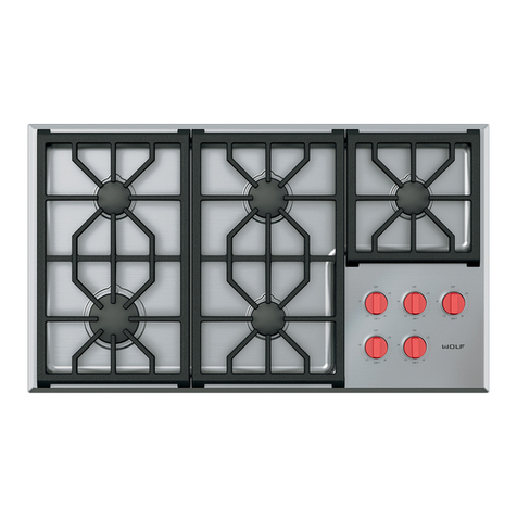
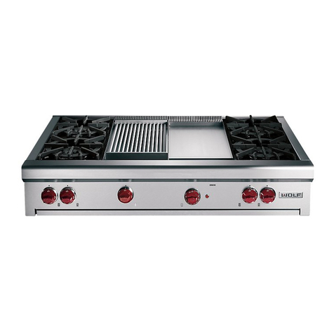
Wolf CG365P/S User manual

Page 2
SERVICE MANUAL INTRODUCTION
This service manual assists with troubleshooting and
diagnosing malfunctions, completion of repairs, and return of
the product to proper operational condition. Read the complete
instructions contained within before initiating any repairs.
This guide is intended for use by Factory Certified Service. Wolf
Appliance, Inc. recommends that repairs be performed by
Factory Certified Service companies only.
Warning and Caution product safety labels appear throughout
this manual. Product safety labels appear at the beginning of
some sections. Follow the instructions in the product safety
labels to avoid personal injury and/or product damage. The
sample safety labels explain the types of notices that appear in
this manual.
WARNING
States a hazard that may cause serious injury or
death if precautions are not followed.
CAUTION
Indicates minor injury or product damage may occur
if precautions are not followed.
IMPORTANT NOTE: Highlights especially important information.
TIP: Indicates additional, useful information.
Information and images contained herein are copyright of Wolf
Appliance, Inc. Neither this manual nor any information or
images contained herein may be copied or used in whole or in
part without the express written consent of Wolf Appliance, Inc.
©Wolf Appliance, Inc., all rights reserved.
WOLF PRODUCT RATING PLATE INFORMATION
For CG Gas Cooktops, the product rating plate is located below
the unit.
Product
Rating Plate
Important information for each product is listed on the product
rating plate. Rating plates identify:
▪Model
▪Serial number
▪Electrical information, including current draw
▪Burner heat ratings (in Btu)
▪Type and pressure of gas
MODEL DESCRIPTIONS AND SALES ACCESSORIES
For more details on individual model descriptions and a listing
of all compatible sales accessories, see the
Wolf Distributor
Price List
.
CG SERIES GAS COOKTOPS MODEL KEY
Model Character Description
ICB International Designation
C Cooktop
G Gas
15, 24, 30, or 36 Size (in Inches)
2, 3, 4, or 5 Number of Burners
C Contemporary
P Professional
T Transitional
F Paired-Frame
S Classic Stainless Steel
LP Liquid Propane (Natural Gas if
Not Present)
PRODUCT USE AND CARE AND INSTALLATION GUIDES
Product Use and Care Guides, Installation Guides, and other
product specifications are available in the
Product
Specifications and Manuals Library
.
CG Contemporary Gas Cooktop Service Manual
General Information
GENERAL INFORMATION
service.subzero.com
828389 REV. A 06/2018 1
Page 3
UNIT WARRANTY
Product warranty is determined by the installation location and
the date of installation.
▪View product warranties at
http://service.subzero.com/
ClaimsAndOrderProcessing/Pages/WarrantyInfo
.
▪Warranties start on the day of product installation.
▪Search for warranty and service information by serial
number, customer last name, and address using Unit
History at
http://service.subzero.com/Tools/UnitHistory
.
CG Contemporary Gas Cooktop Service Manual
General Information
service.subzero.com
828389 REV. A 06/2018 2

Page 4
COMPONENT REMOVAL AND INSTALLATION
SPARK MODULE REMOVAL
TIP: Individual spark modules are accessible through panels on
the bottom of the unit.
WARNING
Turn off the power to the product before starting this
procedure.
Remove the Spark Module
1Use a 1/4" nut driver or socket to remove the screw holding
the igniter bracket to the burner box.
2Lower the screw side of the igniter bracket.
3Disconnect the electrode wire from the spark module.
4Disconnect the red wire connector from the L1 terminal.
5Disconnect the white wire connector from the neutral (N)
terminal.
6Use a Phillips screwdriver to remove the screws holding the
spark module to the igniter bracket.
7Remove the spark module from the unit.
SPARK MODULE INSTALLATION
Install the Spark Module
1Place the spark module onto the igniter bracket.
2Use a Phillips screwdriver to install the screws holding the
spark module to the igniter bracket.
3Connect the white wire connector to the neutral (N)
terminal.
4Connect the red wire connector to the L1 terminal.
5Connect the electrode wire to the spark module.
6Raise the screw side of the igniter bracket.
7Use a 1/4" nut driver or socket to install the screw holding
the igniter bracket to the burner box.
BURNER BOX BOTTOM PANEL REMOVAL
The burner box bottom panel is removable and allows access
to the unit harness. First, remove all spark modules.
Remove All Spark Modules
To remove each spark module:
1Use a 1/4" nut driver or socket to remove the screw holding
the igniter bracket to the burner box.
2Lower the screw side of the igniter bracket.
3Disconnect the electrode wire from the spark module.
4Disconnect the red wire connector from the L1 terminal.
5Disconnect the white wire connector from the neutral (N)
terminal.
6Use a Phillips screwdriver to remove the screws holding the
spark module to the igniter bracket.
CG Contemporary Gas Cooktop Service Manual
Component Removal and Installation
service.subzero.com
828389 REV. A 06/2018 3

Page 5
7Remove the spark module from the unit.
Remove the Burner Box Bottom Panel
1Use a Phillips screwdriver to remove the screws from the
burner box bottom panel.
2Remove the harness from the wire retention clip.
3Remove the burner box bottom panel.
Burner Box
Bottom Panel
Igniter
Brackets
BURNER BOX BOTTOM PANEL INSTALLATION
Install the Burner Box Bottom Panel
1Insert the harness into the wire retention clip.
2Place the burner box bottom panel on the unit.
3Use a Phillips screwdriver to install the screws into the
burner box bottom panel.
Install All Spark Modules
To install each spark module:
1Place the spark module onto the igniter bracket.
2Use a Phillips screwdriver to install the screws holding the
spark module to the igniter bracket.
3Connect the white wire connector to the neutral (N)
terminal.
4Connect the red wire connector to the L1 terminal.
5Connect the electrode wire to the spark module.
6Raise the screw side of the igniter bracket.
7Use a 1/4" nut driver or socket to install the screw holding
the igniter bracket to the burner box.
MANIFOLD BOTTOM COVER REMOVAL
The manifold bottom cover is located on the bottom of the
manifold behind the cabinet face. Removing the manifold
bottom cover allows access to the AC-DC rectifiers and
manifold harness.
TIP: The manifold bottom cover may not be removable
depending on the cabinet design.
Remove the Manifold Bottom Cover
1Use a Phillips screwdriver to remove the screws from the
manifold bottom cover.
CG Contemporary Gas Cooktop Service Manual
REMOVE ALL SPARK MODULES (continued)
service.subzero.com
828389 REV. A 06/2018 4

Page 6
2Remove the manifold bottom cover.
MANIFOLD BOTTOM COVER INSTALLATION
Install the Manifold Bottom Cover
1Place the manifold bottom cover on the unit.
2Use a Phillips screwdriver to install the screws into the
manifold bottom cover.
BURNER GRATE REMOVAL
Remove the Burner Grate
Lift the burner grate from the unit.
BURNER GRATE INSTALLATION
Install the Burner Grate
Place the burner grate onto the cooktop.
BURNER CAP REMOVAL
To remove the burner cap, first remove the burner grate.
Remove the Burner Grate
Lift the burner grate from the unit.
Remove the Burner Cap
Remove the burner cap from the burner assembly.
CG Contemporary Gas Cooktop Service Manual
REMOVE THE MANIFOLD BOTTOM COVER (continued)
service.subzero.com
828389 REV. A 06/2018 5

Page 7
BURNER CAP INSTALLATION
Install the Burner Cap
Place the burner cap onto the burner assembly.
Install the Burner Grate
Place the burner grate onto the cooktop.
KNOB REMOVAL
Remove the Knob
Pull the knob away from the unit.
KNOB INSTALLATION
Install the Knob
Push the knob onto the valve shaft.
BEZEL REMOVAL
To remove the bezel, first remove the knob.
Remove the Knob
Pull the knob away from the unit.
Remove the Bezel
Use a 3/4" socket to remove the bezel from the unit.
BEZEL INSTALLATION
Install the Bezel
1Insert the bezel into the unit.
2Use a 3/4" socket to install the bezel on the unit.
Install the Knob
Push the knob onto the valve shaft.
CG Contemporary Gas Cooktop Service Manual
service.subzero.com
828389 REV. A 06/2018 6

Page 8
LIGHT MODULE REMOVAL
To access the light modules on a Contemporary model, remove
the knobs and bezels.
WARNING
Turn off the power to the product before starting this
procedure.
Remove the Knob
Pull the knob away from the unit.
Remove the Bezel
Use a 3/4" socket to remove the bezel from the unit.
Remove the Light Module
1Pull the light module forward out of the receptacle.
2Disconnect the AC-DC rectifier wire connector from the light
module.
LIGHT MODULE INSTALLATION
Install the Light Module
1Connect the AC-DC rectifier to the light module.
2Insert the tabs of the light module into the receptacle.
3Push the light module into the receptacle.
Install the Bezel
1Insert the bezel into the unit.
2Use a 3/4" socket to install the bezel on the unit.
Install the Knob
Push the knob onto the valve shaft.
BURNER ASSEMBLY REMOVAL
To remove a burner assembly, first remove the burner grate and
burner cap.
CAUTION
The unit might be supported by the burner pan. The
unit must be uninstalled if more than one burner
assembly or the burner pan is being removed.
WARNING
Turn off the power to the product before starting this
procedure.
CG Contemporary Gas Cooktop Service Manual
service.subzero.com
828389 REV. A 06/2018 7

Page 9
Remove the Burner Grate
Lift the burner grate from the unit.
Remove the Burner Cap
Remove the burner cap from the burner assembly.
Remove the Burner Assembly
1Use a T-15 Torx bit to remove the screws holding the burner
assembly to the orifice holder.
2Lift the burner assembly from the burner pan.
3Remove the electrode wire from the igniter.
4Remove the burner assembly from the unit.
Burner Cap
Burner Assembly
Igniter
Electrode Wire
BURNER ASSEMBLY INSTALLATION
Install the Burner Assembly
1Attach the electrode wire to the igniter.
2Place the burner assembly into the burner pan.
3Use a T-15 Torx bit to install the screws holding the burner
assembly to the orifice holder, torqued to 24 in lb.
Install the Burner Cap
Place the burner cap onto the burner assembly.
Install the Burner Grate
Place the burner grate onto the cooktop.
IGNITER REMOVAL
To remove the igniter, first remove the burner grate, burner cap,
and burner assembly.
CG Contemporary Gas Cooktop Service Manual
service.subzero.com
828389 REV. A 06/2018 8

Page 10
Remove the Burner Grate
Lift the burner grate from the unit.
Remove the Burner Cap
Remove the burner cap from the burner assembly.
Remove the Burner Assembly
1Use a T-15 Torx bit to remove the screws holding the burner
assembly to the orifice holder.
2Lift the burner assembly from the burner pan.
3Remove the electrode wire from the igniter.
4Remove the burner assembly from the unit.
Burner Cap
Burner Assembly
Igniter
Electrode Wire
Remove the Igniter
1Use a Phillips screwdriver to remove the screw from the
underside of the burner assembly.
2Remove the igniter from the burner assembly.
IGNITER INSTALLATION
Install the Igniter
1Install the igniter into the burner assembly.
2Use a Phillips screwdriver to install the screw into the
underside of the burner assembly.
Install the Burner Assembly
1Attach the electrode wire to the igniter.
2Place the burner assembly into the burner pan.
3Use a T-15 Torx bit to install the screws holding the burner
assembly to the orifice holder, torqued to 24 in lb.
CG Contemporary Gas Cooktop Service Manual
service.subzero.com
828389 REV. A 06/2018 9

Page 11
Install the Burner Cap
Place the burner cap onto the burner assembly.
Install the Burner Grate
Place the burner grate onto the cooktop.
ORIFICE REMOVAL
The main and simmer orifices are threaded into the orifice
holder and may be removed without removing the orifice holder.
To access the orifice, first remove the burner grate, burner cap,
and burner assembly.
WARNING
Turn off the power to the product before starting this
procedure.
Remove the Burner Grate
Lift the burner grate from the unit.
Remove the Burner Cap
Remove the burner cap from the burner assembly.
Remove the Burner Assembly
1Use a T-15 Torx bit to remove the screws holding the burner
assembly to the orifice holder.
2Lift the burner assembly from the burner pan.
3Remove the electrode wire from the igniter.
4Remove the burner assembly from the unit.
Burner Cap
Burner Assembly
Igniter
Electrode Wire
CG Contemporary Gas Cooktop Service Manual
service.subzero.com
828389 REV. A 06/2018 10

Page 12
Remove the Orifice
Use a 9/32” socket with extension to remove the orifice from
the orifice holder.
Simmer
Orifice
Main
Orifice
ORIFICE INSTALLATION
WARNING
When installing the orifice to the orifice holder, only
pipe thread compound should be used. Do not use
Teflon tape to seal gas connections.
Install the Orifice
Use a 9/32” socket with extension to install the orifice into
the orifice holder.
Install the Burner Assembly
1Attach the electrode wire to the igniter.
2Place the burner assembly into the burner pan.
3Use a T-15 Torx bit to install the screws holding the burner
assembly to the orifice holder, torqued to 24 in lb.
Install the Burner Cap
Place the burner cap onto the burner assembly.
Install the Burner Grate
Place the burner grate onto the cooktop.
BURNER PAN REMOVAL
The burner pan is held to the burner box by the screws that
mount the burner assemblies to the orifice holder assemblies.
To remove the burner pan, first remove all burner grates, burner
caps, knobs, and bezels. Uninstall the unit, and then remove the
burner assemblies.
WARNING
Turn off the power and gas to the product before
starting this procedure.
CAUTION
The unit might be supported by the burner pan. The
unit must be uninstalled if more than one burner
assembly or the burner pan is being removed.
CAUTION
If the gas line is not long enough to stay connected
when the unit is pulled out of the opening, the gas
may need to be disconnected.
Remove All Burner Grates
Lift all burner grates from the unit.
TIP: Remove the center grate first.
CG Contemporary Gas Cooktop Service Manual
service.subzero.com
828389 REV. A 06/2018 11

Page 13
Remove All Burner Caps
Remove all burner caps from the burner assemblies.
Remove All Knobs
Pull all of the knobs away from the unit.
Remove All Bezels
To remove each bezel:
Use a 3/4" socket to remove the bezel from the unit.
Uninstall the Unit
Remove the unit from the installation.
Remove All Burner Assemblies
To remove each burner assembly:
1Use a T-15 Torx bit to remove the screws holding the burner
assembly to the orifice holder.
2Lift the burner assembly from the burner pan.
3Remove the electrode wire from the igniter.
4Remove the burner assembly from the unit.
Burner Cap
Burner Assembly
Igniter
Electrode Wire
Remove the Burner Pan
Lift the burner pan from the burner box.
BURNER PAN INSTALLATION
Install the Burner Pan
Place the burner pan on the burner box.
CG Contemporary Gas Cooktop Service Manual
service.subzero.com
828389 REV. A 06/2018 12

Page 14
Install All Burner Assemblies
To install each burner assembly:
1Attach the electrode wire to the igniter.
2Place the burner assembly into the burner pan.
3Use a T-15 Torx bit to install the screws holding the burner
assembly to the orifice holder, torqued to 24 in lb.
Install the Unit
Install the unit.
Install All Bezels
To install each bezel:
1Insert the bezel into the unit.
2Use a 3/4" socket to install the bezel on the unit.
Install All Knobs
Push each knob onto each valve shaft.
Install All Burner Caps
Install all burner caps onto the burner assemblies.
Install All Burner Grates
Place all burner grates onto the cooktop.
TIP: Place the side grates first and the center grate last.
RECEPTACLE REMOVAL
To remove the receptacle, first remove the grates, burner caps,
knobs, and bezels. Then, remove the unit from the installation
and remove the light modules.
WARNING
Turn off the power to the product before starting this
procedure.
CAUTION
If the gas line is not long enough to stay connected
when the unit is pulled out of the opening, the gas
may need to be disconnected.
Remove All Burner Grates
Lift all burner grates from the unit.
TIP: Remove the center grate first.
Remove All Burner Caps
Remove all burner caps from the burner assemblies.
Remove All Knobs
Pull all of the knobs away from the unit.
CG Contemporary Gas Cooktop Service Manual
service.subzero.com
828389 REV. A 06/2018 13

Page 15
Remove All Bezels
To remove each bezel:
Use a 3/4" socket to remove the bezel from the unit.
Remove the Light Module
1Pull the light module forward out of the receptacle.
2Disconnect the AC-DC rectifier wire connector from the light
module.
Uninstall the Unit
Remove the unit from the installation.
Remove the Receptacle
1Use a Phillips screwdriver to remove the screws from the
receptacle.
2Remove the receptacle from the burner valve.
TIP: The spacer(s) typically remain attached to the receptacle.
RECEPTACLE INSTALLATION
Install the Receptacle
1Install the receptacle onto the burner valve.
2Use a Phillips screwdriver to install the screws into the
receptacle.
Install the Unit
Install the unit.
Install the Light Module
1Connect the AC-DC rectifier to the light module.
2Insert the tabs of the light module into the receptacle.
3Push the light module into the receptacle.
Install All Bezels
To install each bezel:
1Insert the bezel into the unit.
2Use a 3/4" socket to install the bezel on the unit.
Install All Knobs
Push each knob onto each valve shaft.
CG Contemporary Gas Cooktop Service Manual
service.subzero.com
828389 REV. A 06/2018 14

Page 16
Install All Burner Caps
Install all burner caps onto the burner assemblies.
Install All Burner Grates
Place all burner grates onto the cooktop.
TIP: Place the side grates first and the center grate last.
ORIFICE HOLDER REMOVAL
To remove the orifice holder, first remove the burner grates,
burner caps, knobs, and bezels. Uninstall the unit, and then
remove the burner assemblies and the burner pan.
WARNING
Turn off the power to the product before starting this
procedure.
CAUTION
If the gas line is not long enough to stay connected
when the unit is pulled out of the opening, the gas
may need to be disconnected.
Remove All Burner Grates
Lift all burner grates from the unit.
TIP: Remove the center grate first.
Remove All Burner Caps
Remove all burner caps from the burner assemblies.
Remove All Knobs
Pull all of the knobs away from the unit.
Remove All Bezels
To remove each bezel:
Use a 3/4" socket to remove the bezel from the unit.
CG Contemporary Gas Cooktop Service Manual
service.subzero.com
828389 REV. A 06/2018 15

Page 17
Uninstall the Unit
Remove the unit from the installation.
Remove All Burner Assemblies
To remove each burner assembly:
1Use a T-15 Torx bit to remove the screws holding the burner
assembly to the orifice holder.
2Lift the burner assembly from the burner pan.
3Remove the electrode wire from the igniter.
4Remove the burner assembly from the unit.
Burner Cap
Burner Assembly
Igniter
Electrode Wire
Remove the Burner Pan
Lift the burner pan from the burner box.
Remove the Orifice Holder
CAUTION
Do not lift the manifold to remove the tube fittings.
Gas tubes provide support to the manifold.
Deforming the gas tube may cause knob alignment
issues.
1Use a 3/8” combination wrench to remove the simmer gas
line.
2Use a 1/2” combination wrench to remove the main gas line.
3Use a Phillips screwdriver to remove the screws holding the
orifice holder to the sealed burner bracket.
Gas Line
Orifice Holder
Screw
Sealed Burner
Bracket
ORIFICE HOLDER INSTALLATION
Install the Orifice Holder
1Use a Phillips screwdriver to install the two screws holding
the orifice holder to the sealed burner bracket.
2Use a 1/2” combination wrench to connect the main gas
line.
3Use a 3/8” combination wrench to connect the simmer gas
line.
CAUTION
Do not over-torque brass fittings.
Install the Burner Pan
Place the burner pan on the burner box.
Install All Burner Assemblies
To install each burner assembly:
1Attach the electrode wire to the igniter.
2Place the burner assembly into the burner pan.
3Use a T-15 Torx bit to install the screws holding the burner
assembly to the orifice holder, torqued to 24 in lb.
CG Contemporary Gas Cooktop Service Manual
service.subzero.com
828389 REV. A 06/2018 16

Page 18
Install the Unit
Install the unit.
Install All Bezels
To install each bezel:
1Insert the bezel into the unit.
2Use a 3/4" socket to install the bezel on the unit.
Install All Knobs
Push each knob onto each valve shaft.
Install All Burner Caps
Install all burner caps onto the burner assemblies.
Install All Burner Grates
Place all burner grates onto the cooktop.
TIP: Place the side grates first and the center grate last.
AC-DC RECTIFIER REMOVAL
TIP: If servicing one rectifier, determine whether the bottom
manifold cover is easily removable. It may be simpler than
uninstalling the unit.
If it is necessary to uninstall the unit, first remove the burner
grates, burner caps, knobs, bezels, and the necessary light
module. Then, uninstall the unit.
WARNING
Turn off the power to the product before starting this
procedure.
CAUTION
If the gas line is not long enough to stay connected
when the unit is pulled out of the opening, the gas
may need to be disconnected.
Remove All Burner Grates
Lift all burner grates from the unit.
TIP: Remove the center grate first.
Remove All Burner Caps
Remove all burner caps from the burner assemblies.
Remove All Knobs
Pull all of the knobs away from the unit.
CG Contemporary Gas Cooktop Service Manual
service.subzero.com
828389 REV. A 06/2018 17

Page 19
Remove All Bezels
To remove each bezel:
Use a 3/4" socket to remove the bezel from the unit.
Remove the Light Module
1Pull the light module forward out of the receptacle.
2Disconnect the AC-DC rectifier wire connector from the light
module.
Uninstall the Unit
Remove the unit from the installation.
Remove the AC-DC Rectifier
1Disconnect the AC-DC rectifier from the unit harness.
2Cut the wire ties holding the AC-DC rectifier to the manifold.
3Remove the AC-DC rectifier.
AC-DC RECTIFIER INSTALLATION
Install the AC-DC Rectifier
1Place the AC-DC rectifier in the unit.
2Use wire ties to secure the AC-DC rectifier to the manifold.
3Connect the AC-DC rectifier to the unit harness.
Install the Unit
Install the unit.
Install the Light Module
1Connect the AC-DC rectifier to the light module.
2Insert the tabs of the light module into the receptacle.
3Push the light module into the receptacle.
Install All Bezels
To install each bezel:
1Insert the bezel into the unit.
2Use a 3/4" socket to install the bezel on the unit.
Install All Knobs
Push each knob onto each valve shaft.
CG Contemporary Gas Cooktop Service Manual
service.subzero.com
828389 REV. A 06/2018 18

Page 20
Install All Burner Caps
Install all burner caps onto the burner assemblies.
Install All Burner Grates
Place all burner grates onto the cooktop.
TIP: Place the side grates first and the center grate last.
AC-DC RECTIFIER REMOVAL (WITHOUT REMOVING THE UNIT
FROM THE INSTALLATION)
TIP: If servicing one rectifier, determine whether the bottom
manifold cover is easily removable. It may be simpler than
uninstalling the unit.
If it is not necessary to uninstall the unit, first remove the
manifold bottom cover, knob, bezel, and light module.
WARNING
Turn off the power to the product before starting this
procedure.
Remove the Manifold Bottom Cover
1Use a Phillips screwdriver to remove the screws from the
manifold bottom cover.
2Remove the manifold bottom cover.
Remove the Knob
Pull the knob away from the unit.
Remove the Bezel
Use a 3/4" socket to remove the bezel from the unit.
Remove the Light Module
1Pull the light module forward out of the receptacle.
2Disconnect the AC-DC rectifier wire connector from the light
module.
CG Contemporary Gas Cooktop Service Manual
service.subzero.com
828389 REV. A 06/2018 19
Other manuals for CG365P/S
2
Table of contents
Other Wolf Cooktop manuals

Wolf
Wolf CI36560T/S User manual

Wolf
Wolf CT30E/S User manual

Wolf
Wolf ICBCT15E Owner's manual

Wolf
Wolf IM15/S User manual

Wolf
Wolf ICBCT15I/S Owner's manual

Wolf
Wolf CT36U Instructions for use

Wolf
Wolf CT30EU Instructions for use

Wolf
Wolf ICBIM15G Owner's manual

Wolf
Wolf CT15G/S User manual

Wolf
Wolf ICBIM15 User manual

Wolf
Wolf CT30I/S User manual

Wolf
Wolf SRT364C User manual

Wolf
Wolf ICBCT30I User manual

Wolf
Wolf IM15SLP User manual

Wolf
Wolf DF366 Instructions for use

Wolf
Wolf Sealed Burner RangeTop Owner's manual

Wolf
Wolf ICBMM15TF-S User manual

Wolf
Wolf 24 inch E Series User manual

Wolf
Wolf Gas Multi-Function Cooktop User manual

Wolf
Wolf SRT304 User manual