Wolf ICBIS15/S User manual

STEAMER MODULE
INSTALLATION INSTRUCTIONS
MÓDULODE VAPORIZADOR INSTRUCCIONES DE INSTALACIÓN
CUIT VAPEUR INSTRUCTIONS D’INSTALLATION
MODULO PER LA COTTURA ISTRUZIONI PER L’INSTALLAZIONE

3
ENGLISH 4
ESPÃNOL 14
FRANÇAIS 24
ITALIANO 34

As you follow these instructions, you will
notice WARNING and CAUTION symbols.
This blocked information is important for the
safe and efficient installation of Wolf equip-
ment. There are two types of potential
hazards that may occur during installation.
Another footnote we would like to identify is
IMPORTANT NOTE: This highlights informa-
tion that is especially relevant to a problem-
free installation.
signals a situation where minor injury or
product damage may occur if you do not
follow instructions.
states a hazard that may cause serious
injury or death if precautions are not
followed.
WOLF®is a registered trademark of Wolf Appliance Company, Inc.
CONTACT
INFORMATION
Website:
wolfappliance.com

5
INSTALLATION REQUIREMENTS
IMPORTANT NOTE:
Save these Installation
Instructions for the local inspector’s use.
Please read the entire Installation
Instructions prior to installation.
This installation must be completed by a
qualified technician.
Installer:
please retain these instructions
for local inspector’s reference, then leave
them with the homeowner.
Homeowner:
please read and keep
these instructions for future reference and
be sure to read the entire Use & Care
Information prior to use.
IMPORTANT NOTE:
This appliance must be
installed in accordance with local codes. The
correct voltage, frequency and amperage
must be supplied to the appliance from a
dedicated, grounded circuit which is protected
by a properly sized circuit breaker or time
delay fuse. The proper voltage, frequency,
and amperage ratings arelisted on the
product rating plate.
Record the model and serial numbers before
installing the steamer module. Both numbers
are listed on the product rating plate located
on the underside of the module. Refer to the
illustration below.
BEFORE YOU START
IMPORTANT NOTE:
Installation and service
must be performed by a qualified installer or
service agency.
Installation of the steamer module must
meet the minimum clearance requirements
for safe operation. Refer to Site Preparation
onpage 6.
Electrical installation must be adequate
and in compliance with all local codes and
ordinances. Electrical ground is required,
refer to Electrical Requirements on page 10.
The steamer module must be installed with
adrain connection and access to the drain
through the base cabinet. Refer to Drain
Connection on page 8.
If the steamer module is to be used with
any combination of additional cooktop units
or modules, refer to Multiple Cooktop
Installation on page 8.
IMPORTANT NOTE:
Aventilation hood is
recommended (but not required) for use with
the Wolf electric steamer module.
This module is intended for indoor use.
WOLF STEAMER MODULE
Model ICBIS15/S
Rating plate location
Model Number
ICBIS15/S
Serial Number
Location of rating
plate under module

6
LOCATION IN COUNTERTOP
A)
Minimum flat countertop surface. Must be
equal to or greater than the width of the
module(s).
B)
Minimum 152 mm wide clearance from the
module side edge to any combustible
surface up to 457 mm above the countertop
(noted by shaded area).
OVERHEAD CABINET DIMENSIONS
C)
Minimum spacing between overhead side
cabinets must be greater than or equal to
the nominal width of the module(s).
D)
Minimum 457 mm vertical distance from
the countertop to the bottom of side
cabinets within minimum side clearance.
E)
Minimum vertical distance between the
countertop and combustible materials
above the module must be 762 mm.
F)
Minimum 25 mm from rear wall.
G)
Maximum 330 mm depth of overhead and
side cabinets directly above and within side
clearance.
SITE PREPARATION
IMPORTANT NOTE:
Installation of the Wolf
electric steamer module must meet the follow-
ing location requirements. All dimensions
listed are minimum requirements for safe
operation. Refer to the illustration below.
Toeliminate the risk of burns or fire by
reaching over heated surface units,
cabinet storage space located above the
surface units should be avoided. If
cabinet storage is to be provided, the risk
can be reduced by installing a ventilation
hood that protects horizontally a
minimum of 127 mm beyond the bottom
of the cabinets.
Failure to locate the cooktop module
without the proper clearances will result
in a fire hazard.
WOLF STEAMER MODULE
C
G
D
A
B
B
E
F
Minimum installation clearances

7
INSTALLATION SPECIFICATIONS
The illustrations below provide the overall
dimensions, finished cut-out dimensions and
electrical placement for the Wolf electric
steamer module.
The steamer module is designed to fit a
standard 610 mm deep base cabinet with
635 mm deep countertop. Before making the
countertop cut-out, verify that the module will
clear the side walls of the base cabinet below.
178 mm
CUT-OUT TO
COMBUSTIBLE
MATERIALS
(BOTH SIDES)
356 mm
COOKTOP CUT-OUT
WIDTH
356 mm
COOKTOP CUT-OUT
WIDTH
838 mm
RECOMMENDED
CABINET WIDTH
457 mm
NOTE: Application shown allows for installation of two 381 mm modules side-by-side with 838 mm recommended cabinet width. 457 mm
recommended cabinet width for installation of single 381 mm cooktop or module. *Minimum clearance from both side edges of cooktop cut-out
to combustible materials up to 457 mm abovecountertop. **Minimum clearance from rear edge of cooktop cut-out to combustible materials up
to 457 mm abovecountertop.
489 mm
COOKTOP CUT-OUT
DEPTH
64 mm
min
914 mm
STANDARD
FLOOR TO
COUNTERTOP
HEIGHT
330 mm
max 762 mm
COUNTERTOP TO
COMBUSTIBLE
MATERIALS
ABOVE COOKTOP
FRONT OF COUNTERTOP
64 mm
489 mm
COOKTOP
CUT-OUT DEPTH
194
mm
314 mm
DRAIN OUTLET
LOCATION
E
343 mm
381
mm
381 mm
314 mm
152
mm
DRAIN
OUTLET
LOCATION
**64
mm
381 mm
OVERALL
WIDTH
533 mm
OVERALL
DEPTH
343 mm
TO DRAIN
OUTLET
191 mm
MODEL
ICBIS15/S
DIMENSIONS
Overall Width 381 mm
Overall Height 343 mm
Overall Depth 533 mm
Minimum Cabinet Depth 578 mm
Minimum Height Clearance 343 mm
Cut-Out Width 356 mm
Cut-Out Depth 489 mm
Unit dimensions may vary to ± 3 mm.
INSTALLATION INSTRUCTIONS
Overall Dimensions
Installation Specifications
Countertop Cut-Out
Dimensions

8
MULTIPLE COOKTOP INSTALLATION
IMPORTANT NOTE:
Ifthe steamer module is
to be used with a combination of additional
cooktop units or modules with a filler strip,
the cut-out width is calculated by adding the
corresponding units' cut-out dimensions plus
32 mm for each additional unit.
When multiple units are installed side by side,
each unit must have its own separate recom-
mended electrical circuit.
When two or more modules are installed
together, an integrated module filler strip
(IFILLER/S) is recommended. Contact your
Wolf dealer for information on accessories.
IMPORTANT NOTE:
Review specific
installation instructions for product to product
capabilities.
WOLF STEAMER MODULE
INSTALLATION SPECIFICATIONS
DRAIN CONNECTION
IMPORTANT NOTE:
The steamer module
must be installed with a drain connection and
access to the drain through the base cabinet.
For the drain connection, the 16 mm outlet
from the valve will accept a drain hose that
must flow downward to and tie into an
existing sink drain, or a separate drain with a
freefall may be installed. Following local
building codes; your plumber will dictate how
to plumb the unit. As a third option, the
consumer will supply a heat resistant bucket
for drainage in the location of the drain outlet.
Refer to the illustration on page 7 for location
of the drain outlet.
64 mm
min
FRONT OF COUNTERTOP
489 mm
CUT-OUT
DEPTH
743 mm
TWO MODULES WIDTH
1130 mm
THREE MODULES WIDTH OR
1124 mm
/762 mm COOKTOP AND ONE MODULE
1518 mm
FOUR MODULES WIDTH OR
1511 mm
/762 mm COOKTOP AND TWO MODULES OR
1276 mm
/914 mm COOKTOP AND ONE MODULE
356
mm
CUT-OUT
WIDTH
Countertop cut-out dimensions for installation of multiple cooktops
This steamer module must be installed
at least 381 mm away from a Wolf fryer
module, as contact between water and hot
oil may cause burns from steam and hot oil.
If there is no fixed drain connection, use a
heat-resistant receptacle with a minimum
7.6 L capacity. The doors of the base
cabinet must be locked.

9
VENTILATION OPTIONS
IMPORTANT NOTE:
It is recommended that
you operate the Wolf electric steamer module
with either a Wolf cooktop or Pro ventilation
hood or hood liner. Contact your Wolf dealer
for details.
Cooktop Wall Hood –
762 mm or 914 mm
widths in classic stainless steel.
Cooktop Island Hood –
1067 mm width in
classic stainless steel.
Pro Wall Hood –
559 mm, 610 mm or
686 mm depths and 762 mm to 1676 mm
widths in classic stainless steel.
Pro Island Hood –
914 mm to 1676 mm
widths in classic stainless steel.
Pro Hood Liner –
available in widths to
accommodate 914 mm to 1524 mm hoods.
All hoods have welded seams, sealed halogen
lighting and removable, dishwasher-safe
filters.
IMPORTANT NOTE:
Wolf does not recom-
mend the use of downdraft ventilation with the
steamer module.
IMPORTANT NOTE:
When installing a ventila-
tion hood, refer to the specific requirements of
the hood for the minimum dimension to the
countertop.
INSTALLATION INSTRUCTIONS
ACCESSORIES
Optional
accessories are
available through
your Wolf dealer.

10
ELECTRICAL REQUIREMENTS
Required Power Supply
220–240 V AC, 50 Hz, 15 amp service
Maximum Connected Load
2.6 kW
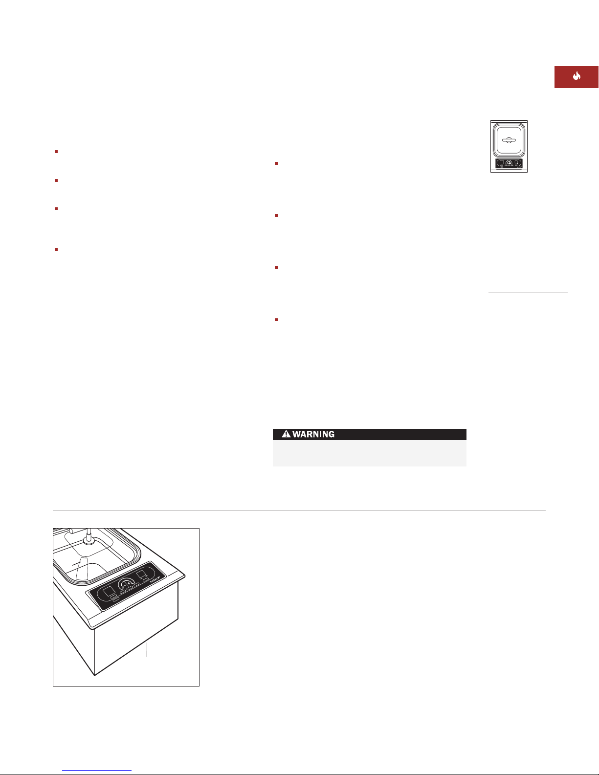
The Wolf electric steamer module requires a
separate, grounded 3-wire 220–240 V AC,
50/60 Hz, 15 amp service with its own circuit
breaker or fuse. A properly rated cord should
be attached to the power supply box of the
steamer as shown in the illustration below.
Open the power box to expose the screws with
corresponding numbers. Loosen the 1, 5, and
ground screws. Run the cordthrough the
circular hole and into the power supply box.
Attach the Neutral wire to the number 1
position. Line should be attached to the 5
position and attach the ground to the corre-
sponding ground screw. After tightening the
screws, close the cover to the power supply
box without pinching any of the wires.
Attach the power cord to the unit before
plugging the cord into the wall.
You must follow local codes and ordinances
when installing your service.
IMPORTANT NOTE:
The correct voltage,
frequency and amperage must be supplied to
the appliance from a dedicated, grounded
circuit which is protected by a properly sized
circuit breaker or time delay fuse. The proper
voltage, frequency, and amperage ratings are
listed on the product rating plate located on
the underside of the module. Refer to the illus-
tration on page 5.
The wiring diagram covering the control circuit
is located inside the module control box.
IMPORTANT NOTE:
To avoid electrical shock
when disconnecting the steamer module, all
poles/wires must be disconnected from the
power supply box.
The complete appliance must be properly
grounded at all times when electrical
power is applied.
Improper connection can result in a fire
hazard!
WOLF STEAMER MODULE
Power supply box

11
MODULE INSTALLATION
To prevent pollution from entering the
controller and transformer area, attach the
foam strip to the underside of the module
frame. Refer to the illustration below.
Gently lower the steamer module into the cut-
out area in the countertop and center. Check
that the front edge of module is parallel to the
front edge of the countertop. Check that all
required clearances are met.
To attach the brackets to the sides of the
module, insert the clip into the rectangular
punchout in the pan, and push down. Install
the clamping screw into the bracket and
tighten until the screw contacts the underside
of the countertop. Do not overtighten screws.
Refer to the illustration below.
IMPORTANT NOTE:
Do not use caulk or
silicone to seal the module to the countertop.
The unit must be readily removable for
service.
BEFORE OPERATING
Read the entire Wolf Steamer Module Use &
Care Information included with the module.
Important safety and service information is
contained within the book.
Thoroughly clean the stainless steel steamer
basin and insert pans with mild soap and
water before use.
MODULE
FOAM
STRIP
89 mm
CLAMPING
SCREW
MODULE
COUNTERTOP
BRACKET
CLIP
Foam strip Installation brackets
INSTALLATION INSTRUCTIONS
Never operate the steamer module
without water, damage to the unit may
result. Water or liquid must be added to
the steamer basin before turning the
module on. Never use oil, damage to the
unit may result.

12
TROUBLESHOOTING
IMPORTANT NOTE:
If the steamer module
does not operate properly, follow these
troubleshooting steps:
Verify that power is being supplied to the
module.
Check electrical connections to ensure that
the installation has been completed
correctly.
Follow troubleshooting procedures as
described in the Wolf Steamer Module
Use & Care Information.
If the module still does not work, contact
your Wolf dealer or regional distributor. Do
not attempt to repair the cooktop module
yourself.
MODULE REMOVAL
IMPORTANT NOTE:
Removal of the steamer
module should only be performed by a Wolf
service center technician.
Ifremoving the steamer module is necessary
for cleaning or service, first disconnect the
electric supply. Remove the mounting brackets
oneach side of module and remove. To
reinstall, refer to page 11.
The module must be disconnected from
power prior to removal and service.
WOLF STEAMER MODULE

13
IF YOU NEED SERVICE
For service in your area, contact either your
Wolf dealer or visit the Locator page of our
website,
wolfappliance.com
tofind the
regional distributor by country.
When calling for service, be sure to have
the model and serial number of the steamer
module. Both numbers are listed on the
product rating plate located on the under-
side of the module. Refer to the illustration
on page 5.
IMPORTANT NOTE:
Installation and service
must be performed by a qualified installer or
service agency.
INSTALLATION INSTRUCTIONS
The information and images are the copyright
property of Wolf Appliance Company, Inc., an
affiliate of Sub-Zero Freezer Company, Inc.
Neither this book nor any information or images
contained herein may be copied or used in whole
or in part without the express written permission
of Wolf Appliance Company, Inc., an affiliate of
Sub-Zero Freezer Company,Inc.
©Wolf Appliance Company, Inc. all rights reserved.
CONTACT
INFORMATION
Website:
wolfappliance.com

Amedida que sigue las instrucciones que
aparecen en esta guía, encontrará símbolos
de AVISO y PRECAUCIÓN. Esta información
es importante para instalar el equipo de Wolf
de forma segura y eficaz. Existen dos tipos
de riesgos potenciales que pueden surgir
durante la instalación.
Otro tipo de anotación que debe identificar
es la que se incluye en NOTA IMPORTANTE:
En esta nota se resalta la información que
resulta especialmente importante para que la
instalación se pueda realizar sin problemas.
indica una situación en la que se pueden
sufrir heridas leves o provocar daños
secundarios al producto si no se siguen
las instrucciones.
indica peligro de que se produzcan heridas
personales graves o incluso puede provocar
la muerte si no se siguen las precauciones
advertidas.
WOLF®es una marca comercial registrada de Wolf Appliance Company, Inc.
INFORMACIÓN
DE CONTACTO
Página Web:
wolfappliance.com

15
REQUISITOS DE INSTALACIÓN
NOTA IMPORTANTE:
Guarde estas instruc-
ciones de instalación para que el inspector
pueda utilizarlas.
Lea las instrucciones de instalación antes
de llevar a cabo la instalación.
La instalación debe ser realizada por un
técnico cualificado.
Instalador:
guarde estas instrucciones para
que el inspector pueda utilizarlas como
referencia y, a continuación, entréguelas
el propietario del aparato.
Propietario:
lea y guarde estas instruc
ciones para que pueda utilizarlas como
referencia en el futuro y asegúrese de leer
la guía de uso y mantenimiento antes de
utilizar el módulo.
NOTA IMPORTANTE:
Este aparato debe ser
instalado siguiendo las normativas nacionales
correspondientes. Se debe aplicar al aparato el
voltaje, la frecuencia y el amperaje adecuados
desde una instalación eléctrica resistente con
toma de tierra y protegida por un fusible de
retardo. El voltaje, la frecuencia y el amperaje
se muestran en la placa de datos de voltaje del
producto.
Apunte la referencia del modelo y el número
de serie antes de instalar el módulo de vapor-
izador.Esta información se muestra en la placa
de datos de voltaje del producto situada en la
parte inferior del módulo. Observe la siguiente
ilustración.
ANTES DE COMENZAR
NOTA IMPORTANTE:
La instalación y el
mantenimiento deben ser realizados por un
instalador cualificado o por un centro de
asistencia técnica.
La instalación del módulo de vaporizador
debe cumplir los requisitos mínimos de
espacio para que funcione de manera segura
yeficaz. Consulte la sección Preparación del
sitio en la página 16.
La instalación eléctrica debe ser la adecuada
ydebe cumplir las normativas y ordenanzas
nacionales sobre instalaciones eléctricas.
Este aparato necesita una conexión a tierra;
consulte la sección Requisitos eléctricos en
la página 20.
El módulo de vaporizador debe instalarse
con una conexión de desagüe a la que se
pueda obtener acceso a través del armario
inferior. Consulte la sección Conexión de
desagüe en la página 18.
Si el módulo de vaporizador se va a utilizar
con otra combinación de módulos o
unidades de cocción adicionales, consulte
la sección Instalación de otras superficies
de cocción en la página 18.
NOTA IMPORTANTE:
Se recomienda utilizar
una campana extractora con el módulo de
vaporizador eléctrico de Wolf, aunque no
es obligatorio.
Este módulo está diseñado para que se
utilice en espacios interiores.
MÓDULO DE VAPORIZADOR DE WOLF
Modelo ICBIS15/S
Ubicación de la placa de voltaje
Referencia
del modelo
ICBIS15/S
Número
de serie
Ubicación de la
placa de datos de
voltaje debajo
del módulo

16
COLOCACIÓN EN LA ENCIMERA
A)
Superficie mínima de encimera plana. Debe
ser igual o superior al ancho del módulo o
módulos.
B)
Espacio mínimo de 152 mm desde el borde
lateral del módulo a cualquier superficie
combustible situada 457 mm por encima
de la encimera (área sombreada de la
ilustración).
MEDIDAS DE LOS ARMARIOS
SUPERIORES
C)
El espacio mínimo entre los armarios superi-
ores laterales debe ser igual o superior al
ancho nominal del módulo o módulos.
D)
Debe existir una distancia vertical mínima
de 457 mm desde la encimera hasta la parte
inferior de los armarios laterales con una
distancia lateral mínima.
E)
La distancia vertical mínima entre la
encimera y los materiales combustibles
superiores debe ser de 762 mm.
F)
Distancia mínima de 25 mm a la pared
trasera.
G)
El fondo máximo de los armarios superiores
ylaterales, situados en la parte superior,
debe ser de 330 mm con una distancia
lateral mínima.
PREPARACIÓN DEL SITIO
NOTA IMPORTANTE:
La instalación del
módulo de vaporizador eléctrico de Wolf debe
cumplir los siguientes requisitos de colocación.
Las medidas que se especifican son las
mínimas para que el funcionamiento del
módulo sea seguro. Observe la siguiente
ilustración.
Para eliminar el riesgo de sufrir
quemaduras o de que se produzca un
incendio al tocar las superficies calientes,
debe evitar colocar armarios por encima
de los módulos de superficie. Si va a
colocar armarios, el riesgo se puede
reducir instalando una campana de
extracción que sobresalga horizontal-
mente un mínimo de 127 mm de la parte
inferior de los armarios.
Si no coloca la superficie de cocción
manteniendo las distancias de separación
adecuadas, existirá riesgo de incendio.
MÓDULO DE VAPORIZADOR DE WOLF
C
G
D
A
B
B
E
F
Distancias mínimas de instalación

17
ESPECIFICACIONES DE LA
INSTALACIÓN
Las siguientes ilustraciones proporcionan las
medidas totales, las medidas de corte acabado
yla colocación de la conexión eléctrica del
módulo de vaporizador eléctrico de Wolf.
El módulo de vaporizador está diseñado para
que se adapte a un armario inferior de 610 mm
de fondo con una encimera de 635 mm de
fondo. Antes de cortar la encimera, compruebe
que el módulo va a quedar separado de las
paredes laterales del armario inferior.
DIMENSIONES DEL MODELO
ICBIS15/S
Anchura total 381 mm
Altura total 343 mm
Fondo total 533 mm
Fondo mínimo del armario 578 mm
Espacio mínimo de altura 343 mm
Ancho del corte 356 mm
Fondo del corte 489 mm
Las medidas de la unidad puede variar en ± 3 mm.
INSTRUCCIONES DE INSTALACIÓN
Medidas totales
Especificaciones de la instalación
Medidas de corte
de la encimera

18
INSTALACIÓN DE OTRAS
SUPERFICIES DE COCCIÓN
NOTA IMPORTANTE:
Si el módulo de vapor-
izador se va a utilizar con otros módulos o
unidades de cocción adicionales con un embe-
llecedor, el ancho del corte se calcula añadiendo
las medidas de corte de la unidad correspondi-
ente más 32 mm por cada unidad adicional.
Cuando se instalen varias unidades juntas,
cada unidad debe tener un circuito eléctrico
propio recomendado.
Cuando se instalen dos o más módulos
juntos, se recomienda utilizar un embellecedor
(IFILLER/S) de módulo integrado. Póngase en
contacto con su distribuidor de Wolf para
obtener información sobrelos accesorios.
NOTA IMPORTANTE:
Revise las instrucciones
de instalación específicas para conocer las
capacidades de cada uno de los productos.
MÓDULO DE VAPORIZADOR DE WOLF
ESPECIFICACIONES DE LA
INSTALACIÓN
CONEXIÓN DE DESAGÜE
NOTA IMPORTANTE:
El módulo de vapor-
izador debe instalarse con una conexión de
desagüe a la que se pueda obtener acceso
através del armario inferior.
Para la conexión de desagüe, la salida de
16 mm de la válvula admite una manguera de
drenaje que debe fluir de manera descendente
yunirse a un desagüe existente o a un
desagüe independiente de caída libre. Siguien-
do la normativa nacional de construcción,
el fontanero determinará cómo realizar las
conexiones de fontanería. Como tercera opción,
el cliente puede proporcionar un recipiente
resistente al calor para colocarlo en la salida
del desagüe. Consulte la ilustración de la
página 17 para ubicar la salida del desagüe.
64 mm
min
PARTE DELANTERA DE LA ENCIMERA
489 mm
FONDO
DE CORTE
743 mm
ANCHURA DE DOS MÓDULOS
1130 mm
ANCHURA DE TRES MÓDULOS O
1124 mm
SUPERFICIE DE COCCIÓN Y UN MÓDULO
1518 mm
ANCHURA DE CUATRO MÓDULOS O
1511 mm
SUPERFICIE DE COCCIÓN Y DOS MÓDULOS O
1276 mm
SUPERFICIE DE COCCIÓN Y UN MÓDULO
356 mm
ANCHURA
DE CORTE
Dimensiones de corte de la encimera para la instalación
de otras superficies de cocción
Este módulo de vaporizador debe instalarse
manteniendo una distancia de al menos
381 mm respecto al módulo de freír de Wolf
ya que el contacto entre el agua y el aceite
caliente puede causar quemaduras provo-
cadas por el vapor yel aceite caliente.
Si no existe ninguna conexión de desagüe
fija, utilice un recipiente resistente al
calor con una capacidad mínima de 7,6 L.
Las puertas del armario inferior deben
estar cerradas.

19
OPCIONES DE VENTILACIÓN
NOTA IMPORTANTE:
Se recomienda utilizar
el módulo de vaporizador eléctrico de Wolf con
una superficie de cocción de Wolf o con una
campana extractora o integrable de la serie
Pro. Póngase en contacto con su distribuidor
deWolf para obtener más detalles.
Campana de pared –
762 mm ó 914 mm
de ancho en acero inoxidable clásico.
Campana isla –
1067 mm de ancho en
acero inoxidable clásico.
Campana de pared Pro–
559 mm, 610 mm
ó686 mm de fondo y 762 mm a 1676 mm
de ancho en acero inoxidable clásico.
Campana isla Pro –
914 mm a 1676 mm
de ancho en aceroinoxidable clásico.
Campana integrable Pro –
disponible en
distintos anchos para que se pueda ajustar
acampanas de 914 mm a 1524 mm.
Todas las campanas tienen uniones soldadas,
lámparas halógenas herméticas y filtros
extraíbles que se pueden lavar en el lavavajillas
de manera segura.
NOTA IMPORTANTE:
Wolf no recomienda
utilizar el extractor de superficie con el módulo
de vaporizador.
NOTA IMPORTANTE:
Cuando instale una
campana extractora, consulte los requisitos
específicos de la campana para obtener las
medidas mínimas que debe mantener respecto
ala encimera.
INSTRUCCIONES DE INSTALACIÓN
ACCESORIOS
Podrá disponer
de accesorios
opcionales a
través de su
distribuidor
de Wolf.

20
REQUISITOS ELÉCTRICOS
Alimentación eléctrica requerida
220–240 V CA, 50 Hz, 15 amperios
Carga máxima conectada
2,6 kW
El módulo de vaporizador eléctrico de Wolf
requiere una red eléctrica de 220–240 V CA,
50/60 Hz y 15 amperios, individual con toma a
tierra con un cable de tres hilos y con su propio
cortacircuitos o fusible. Debe conectar un cable
apto para el voltaje correspondiente a la caja de
suministro eléctrico del módulo tal y como se
muestra en la siguiente ilustración. Abra la caja
de suministroeléctrico para ver los tornillos con
los números correspondientes. Afloje los torni-
llos 1, 5 y el tornillo de conexión a tierra. Pase
el cable por el agujerocircular e introdúzcalo en
la caja de suministro eléctrico. Conecte el cable
neutro en la posición número 1. El cable de
línea debe conectarse en la posición número 5
yel cable de conexión a tierra en el tornillo de
conexión a tierra correspondiente. Una vez que
haya apretado los tornillos, cierre la tapa de la
caja de suministroeléctrico asegurándose de
que los cables no quedan enganchados.
Conecte el cable de alimentación a la
unidad antes de conectar éste a la toma
de pared.
Deberá cumplir las ordenanzas y normativas
nacionales cuando instale el aparato.
NOTA IMPORTANTE:
El voltaje, la frecuencia
yel amperaje correctos deben suministrarse
desde una red eléctrica adecuada con toma de
tierra y fusible de retardo. El voltaje, la frecuen-
cia y el amperaje correctos se muestran en la
placa de datos de voltaje del producto situada
en la parte inferior del módulo. Consulte la
ilustración de la página 15.
El diagrama de cableado que incluye informa-
ción sobre el circuito de control está situado
dentro de la caja de control del módulo.
NOTA IMPORTANTE:
Para evitar que se
produzca una descarga eléctrica al desconectar
el módulo de vaporizador, debe desconectar
el aparato de la red eléctrica.
El aparato debe estar conectado a tierra
de manera correcta siempre que esté
conectado a la red eléctrica.
Si la conexión no se realiza de manera
correcta, existe riesgo de que se
produzca un incendio.
MÓDULO DE VAPORIZADOR DE WOLF
Caja de suministro eléctrico

21
INSTALACIÓN DEL MÓDULO
Para evitar que entre suciedad en el área del
controlador y del transformador, coloque el
embellecedor en la parte inferior del marco
del módulo. Observe la siguiente ilustración.
Coloque con cuidado el módulo de vaporizador
en el área recortada de la encimera y céntrelo.
Compruebe que el borde delantero del módulo
se coloca en paralelo al borde delantero de la
encimera. Compruebe que se han dejado los
espacios mínimos requeridos.
Para colocar los soportes en los laterales del
módulo, inserte el fijador en el hueco rectangu-
lar de la bandeja y presione hacia abajo. Instale
el tornillo de sujeción en el soporte y apriételo
hasta que el tornillo toque la parte inferior de la
encimera. No apriete los tornillos demasiado.
Observe la siguiente ilustración.
NOTA IMPORTANTE:
No utilice masilla ni
silicona para sellar el módulo a la encimera.
La unidad debe extraerse con facilidad para
realizar las tareas de mantenimiento.
ANTES DE UTILIZAR LA UNIDAD
Lea la guía de uso y mantenimiento del módulo
de vaporizador de Wolf que se incluye con el
módulo. Esta guía contiene información impor-
tante sobre la seguridad y el mantenimiento
del módulo.
Limpie con detenimiento la cubeta del vapor-
izador y las bandejas de acero inoxidable con
detergente suave y agua antes de utilizarlas.
MÓDULO
EMBELLECEDOR
Embellecedor Soportes de instalación
INSTRUCCIONES DE INSTALACIÓN
No ponga nunca en funcionamiento el
módulo de vaporizador sin agua ya que
se podrían producir daños en la unidad.
El agua o el líquido debe añadirse a la
cubeta del vaporizador antes de encender
el módulo. No utilice nunca aceite ya que
se podrían producir daños en la unidad.
Table of contents
Languages:
Other Wolf Electric Steamer manuals