Wolf CWL-300 Excellent User manual

HEAT-RECOVERY-UNIT
CWL - 300 (B)
CWL - 400 (B)
WITH OPTION-PCB
Installation Instructions
Wolf GmbH D-84048 Mainburg Postbox 1380 Tel. +49(0)8751/74-0 Fax +49(0)8751/741600 Internet www.wolf-heiztechnik.de
$UW1U 0RGL¿FDWLRQVUHVHUYHG
D
GB

2 Heat Recovery unit CWL-300(B) / CWL-400(B) with option PCB
Table of contents
Application 1 3
Assembly option PCB Assembly option PCB by installer
Connections option PCB
24
5
Controlpanel LED-display controlpanel
Menustrukture controlpanel
36
6
Settings Reading out settings
Reading out settings by the user
Reading out settings by the installer
Read out data user/ installer
Modifying settings
Modifying settings bij the user
Modifying settings by the installer
Explanation setting parameters
Setting range and factory settings parameters
Modifying setting parameters
Switch input incident
6ZLWFKLQSXWEHGURRPYDOYH
Programmable contact 1
Programmable contact 2
Humidity sensor input
Input for CO2-sensor
Control postheater up to 1000 W
Control preheater up to 1000 W
47
7
7
7
7
7
9
10
11
12
12
12
12
12
12
12
12
12
Faults Fault codes table 513
Electric diagrams &RQQHFWLRQGLDJUDPEHGURRPYDOYH9$&
&RQQHFWLRQGLDJUDPÀXHJDVYDOYH9$&
Wiring diagram proportional input 1
Wiring diagram proportional input 2
Wiring diagram postheater
Wiring diagram preheater
614
14
15
15
16
16
Service $UWLFOHFRGHVVHUYLFHSDUWV
Notes
717
17
Declaration of conformity 18
Chapter Page

Heat Recovery unit CWL-300(B) / CWL-400(B) with option PCB 3
Application Chapter 1
The functionality of CWL 300 & 400 can be extended with the
VHSDUDWHO\DYDLODEOHRSWLRQSFE
7KLVRSWLRQSFEDOORZVFRQQHFWLRQRIYDULRXVH[WUDV7KLVPD-
QXDO GHVFULEHV KRZ WKH YDULRXV FRQQHFWLRQV PXVW EH PDGH
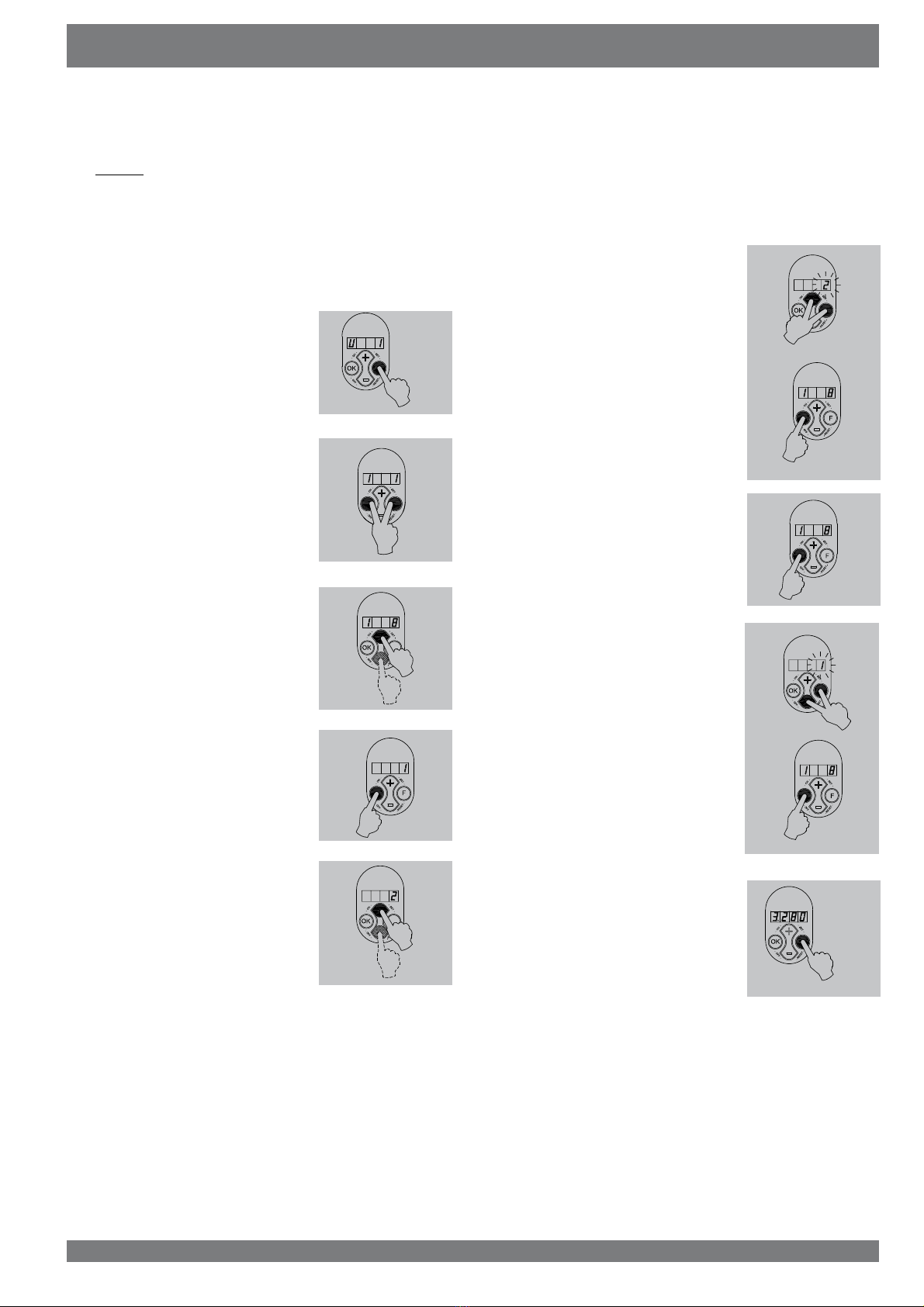
(§ 2.2 and chapter 6) and what the setting parameters are
(§ 4.3). For general information on the CWL-series we refer to
the installation instructions of the CWL- 300/400.
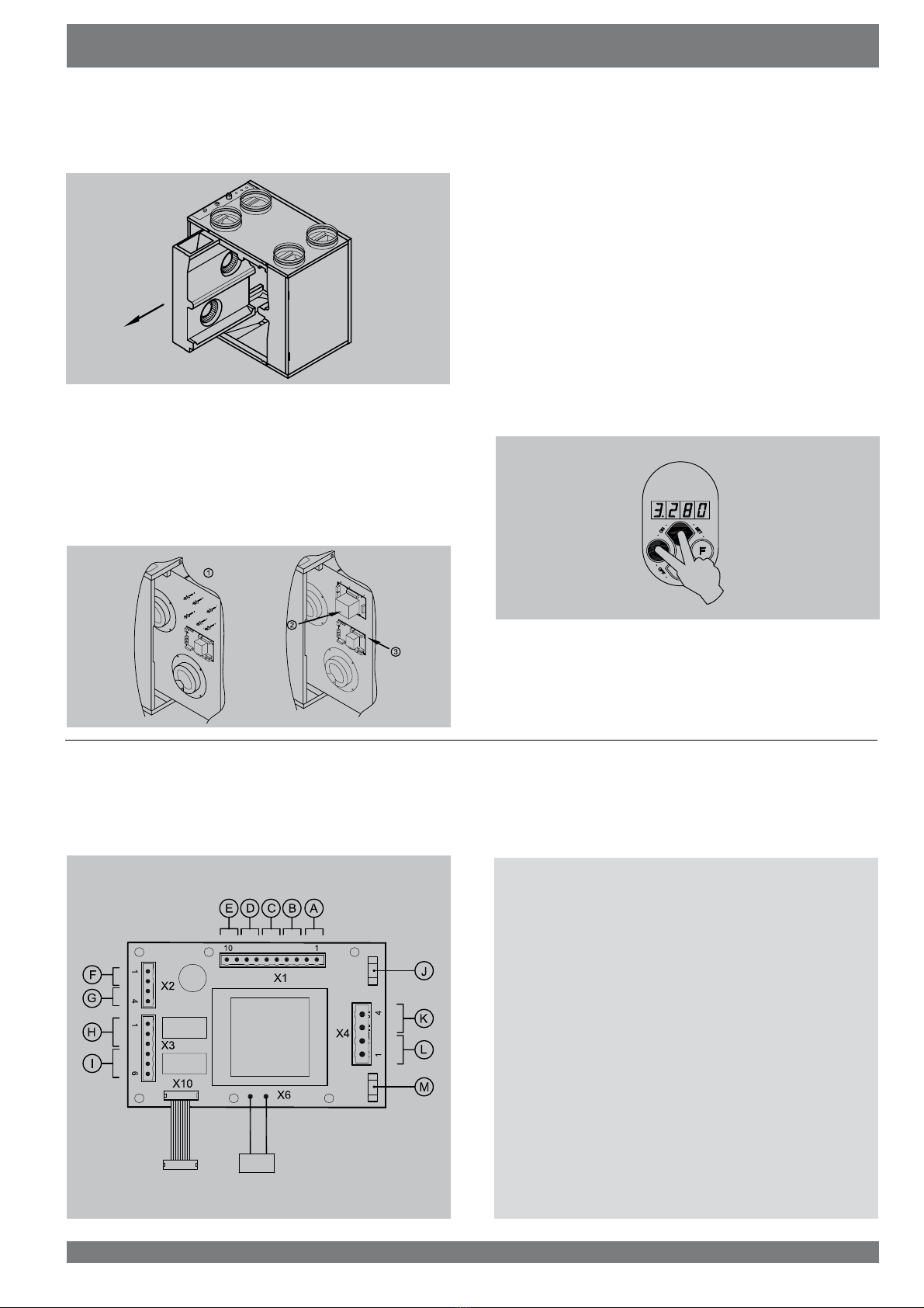
The CWL-appliance can be equipped with an option pcb.
,WSURYLGHVWKHIROORZLQJIXQFWLRQV
Input 0-10 V for a carbon dioxide sensor
When there are more people in the home, more CO
2
is produ-
FHGDQGWKHQWKLVVHQVRU DXWRPDWLFDOO\ LQFUHDVHV WKHYHQWLOD-
tion quantity. For that purpose the CO
2
VHQVRUPXVWKDYHDWR
PD[LPXP9FRQWURO
Input 0-10 V for a moisture sensor
When the moisture content in the dwelling increases, for in-
stance when someone is taking a shower, this sensor automa-
WLFDOO\ LQFUHDVHV WKH YHQWLODWLRQ TXDQWLW\ 7KH PRLVWXUH VHQVRU
PXVWKDYHDWRPD[LPXP9FRQWURO
Switching input for bedroom valve.
:LWKWKLVLQSXWPDNHFRQWDFWWKHEHGURRPYDOYHFDQEHFRQ-
trolled, for example by using a time switch.
Switching output for bedroom valve 24 VAC
7KH RSWLRQ SFE KDV D EXLOWLQ FRQWURO IRU D 9$& EHGURRP
YDOYH6XFKDYDOYHFDQGLUHFWO\EHFRQQHFWHGWRWKHSFE7KH
YDOYH FDQ EH FRQWUROOHG IURP WKH VZLWFKLQJ LQSXW IRU WKH EH-
GURRPYDOYH
6ZLWFKLQJRXWSXWIRU9$&ÀXHJDVVDIHW\YDOYH
If it is recommended to combine the discharge of the central
heating and the CWL appliance, the CWL connection to the
MRLQWGLVFKDUJHPXVWEHSURWHFWHGZLWKDÀXHJDVVDIHW\YDOYH
7KHYDOYHFDQGLUHFWO\EHFRQQHFWHGWRWKLVSFE:KHQWKHRXW-
SXWIDQKDVVWRSSHGRULILWLVGHIHFWLYHWKLVYDOYHLVDFWLYDWHG
Control for preheater up to 1000 W
7KHSUHKHDWHUHQVXUHVWKDWWKHLQSXWDLULVNHSWDERYH&VR
WKH&:/DSSOLDQFHFDQFRQWLQXHWKHEDODQFHGYHQWLODWLRQDOVR
DW YHU\ ORZ DWPRVSKHULF WHPSHUDWXUHV
The option pcb con-
tains a control for a preheater up to 1000 W.
The preheater can
be connected to the option pcb without separate control. The
hook-up wire of the preheater must be fed into the appliance;
WKH 9 SRZHU FDEOH PXVW VHSDUDWHO\ EH FRQQHFWHG WR WKH
option pcb (see § 6.6).
It is also possible to connect a preheater to the basic pcb of the
CWL-appliance if no option pcb is mounted (see §9.4 of the
installation instructions CWL-300/400).
Control for postheater up to 1000 W
The postheater ensures that the supply air that is blown into
the dwelling can be kept at the preset temperature. That way
additional warmth can be brought into the dwelling. The option
pcb contains a control for a postheater up to 1000 W. The pos-
theater can be connected to the option pcb without separate
control. The hook-up wire of the postheater must be fed into
WKHDSSOLDQFHWKH9SRZHUFDEOHPXVWVHSDUDWHO\EHFRQ-
nected to the option pcb (see § 6.5).
Two freely programmable make contact inputs
These inputs make it possible :
• to open the bypass without regard for the temperature con-
ditions;
WRVZLWFKWKHLQSXWRURXWSXWORZRUKLJKWRFLUFXPYHQWWKH
frost protection;
• to switch the input low when the bypass opens.
Switch input for incidents
$¿UHDODUPFDQEHFRQQHFWHGWRWKLVLQSXW$VVRRQDVWKH¿UH
alarm is triggered, the appliance switches to incident mode.
As standard that is set to switch off the fans.

4 Heat Recovery unit CWL-300(B) / CWL-400(B) with option PCB
1 Switch off the appliance on the control panel (simulta-
neously press keys "OK” and “-“ for 3 seconds) and switch
off the power supply.
2SHQWKH¿OWHUGRRU
5HPRYHWKH¿OWHUV
5HPRYHWKHIURQWFRYHU
4 If the appliance is equipped with the optional bypass unit,
LWPXVWQRZEHUHPRYHG
)LUVWUHPRYHWKHGLVSOD\VHHLWHPIRUDSSOLDQFHZLWKRXW
bypass unit) and unscrew the four hexagon socket bolts
0[SXOORXWWKHFRQQHFWRUVDQGUHPRYHWKHE\SDVV
unit from the appliance.
5HPRYHWKHFRQWUROSDQHO
5HPRYHWKHKHDWH[FKDQJHU%HFDUHIXOQRWWRGDPDJHWKH
foam parts in the appliance.
Chapter 2 Assembly option PCB
5388-A
5418-0
2.1 Assembly option pcb by installer
Only for CWL-appliance equipped with the
optional bypass unit!
without bypass unit with bypass unit

Heat Recovery unit CWL-300(B) / CWL-400(B) with option PCB 5
7 Slide the fan unit forward from the appliance far enough to
access the basic pcb.
8 Mount the 6 pcb feet that came with the option pcb. Then
press the option pcb on the pcb feet and connect the 2
cables from the option pcb to the basic pcb (connector X12
and X13; see also §9.4 in the installation instructions CWL
300/400). Connect the desired options to the option pcb;
UHPRYHWKHVHDOLQJSOXJVPRXQWWKHQHFHVVDU\VZLYHOVLQ
the top panel and feed the additional cables through those
out of the appliance.
9 Slide the fan unit back into the appliance.
5H¿WWKHFRQWUROSDQHO)RUDQDSSOLDQFHZLWKE\SDVVXQLW
¿UVWPRXQWWKHKHDWH[FKDQJHUDQGWKHE\SDVVXQLW
11 Place the heat exchanger back into the appliance.
3ODFHWKHIURQWFRYHU
3ODFHWKH¿OWHUVLQWKHDSSOLDQFHZLWKWKHFOHDQVLGHIDFLQJ
the exchanger.
&ORVHWKH¿OWHUGRRUDQGVZLWFKRQWKHSRZHUVXSSO\
15 Switch on the appliance on the control panel (simultane-
ously press keys “OK” and “+“ for 3 seconds).
$IWHUFOHDQLQJWKH¿OWHURUDSODFLQJDQHZ¿OWHUWKH¿OWHULQ-
dication must be reset by pressing key “OK” for 1 second.
Assembly option PCB Chapter 2
5383-0
5442-0
2.2 Connections option pcb
7KH RSWLRQ SFE LV ¿WWHG ZLWK D QXPEHU RI VFUHZ FRQQHFWRUV
7KHVHFDQEHXVHGWRFRQQHFWYDULRXVFRPSRQHQWV7KH¿JXUH
EHORZVKRZVWKHORFDWLRQRIWKHYDULRXVWHUPLQDOV
The moment the option pcb is connected, it will automatically
be detected by the basic pcb.
A = Switching input for incident
% 6ZLWFKLQJLQSXWIRUEHGURRPYDOYH
C = Programmable make contact P1
D = Programmable make contact P2
E = Temperature sensor postheater
F = Input moisture sensor
G = Input CO
2
sensor
+ 6ZLWFKLQJRXWSXWIRUEHGURRPYDOYH9$&
, 6ZLWFKLQJRXWSXWÀXHJDVYDOYH9$&
J = Fuse postheater 4AT
K = Switching output postheater
L = Switching output preheater
M = Fuse preheater 4AT

6 Heat Recovery unit CWL-300(B) / CWL-400(B) with option PCB
7KH&:/DSSOLDQFHLV¿WWHGZLWKDFRQWUROSDQHO,WFDQEHXVHG
WRUHWULHYHDQGPRGLI\WKHVHWWLQJVLQWKHFRQWUROXQLWSURJUDP
The control panel has four keys and a display
2QWKHOHIW WKH GLVSOD\LQGLFDWHV WKH YHQWLODWLRQVHWWLQJ RU WKH
SDUDPHWHU W\SH 2Q WKH ULJKW LW VKRZV WKH UHDGRXW YDOXH IRU
LQVWDQFHWKHSUHVHWDLUÀRZ
7KHNH\VKDYHWKHIROORZLQJIXQFWLRQV
• F Function key / switching on and off parameter menu
1H[WSDUDPHWHULQFUHDVHYDOXH
3UHYLRXVSDUDPHWHUGHFUHDVHYDOXH
• OK Switching on and off settings menu / manual
IDXOWUHVHW¿OWHULQGLFDWLRQUHVHW
Other commands can be entered with key combinations.
)VHW FRQ¿UPSDUDPHWHUYDOXH
)UHVHW SDUDPHWHUYDOXHEDFNWRIDFWRU\
setting
• OK & + (ON), switch on appliance
• OK & - (OFF), switch off appliance
:KHUHYHUWKLVERRNOHWVWDWHVWKDWDNH\KDVWREHSUHVVHGWKH
key in question is printed in quotation marks and in bold.
Example: - press key “OK”.
Chapter 3 Controlpanel
5493-0
Controlpanel
5493-1
3.1 LED display control panel
1 = Display
.H\³2.´FRQ¿UPUHDG\¿OWHULQGLFDWLRQUHVHW
3 = Key increase parameter
4 = Function key
5 = Key reduce parameter
Example:
The display now shows that the
DSSOLDQFHLVUXQQLQJDWYHQWLODWL-
RQVHWWLQJDWDÀRZUDWHRI
m³/h.
3.2 Menu structure control panel
7KHPHQXVWUXFWXUHLVGLYLGHGLQWRDUHDGRXWVHFWLRQDQGDVHW-
WLQJV VHFWLRQ 7KH QXPEHU RI YLVLEOH SDUDPHWHUV GHSHQGV RQ
the parameter set. The user has the parameter set "user"; a
PRUHFRPSUHKHQVLYHSDUDPHWHUVHWLQVWDOOHULVDYDLODEOHIRU
the installer.

Heat Recovery unit CWL-300(B) / CWL-400(B) with option PCB 7
$ PRUH FRPSUHKHQVLYH UHDGRXW SURJUDP LV DYDLODEOH IRU WKH
installer. Pressing keys “F” and “OK” for 3 seconds calls up all
LQVWDOOHUGDWD,QWKLVPHQXWKHYDOXHVcannotEHPRGL¿HG
$FWLYDWLQJWKLVPHQXDOZD\VFDOOVXSVWHSQRVHHWDEOHVHF-
tion 4.2.1); pressing key "+" calls up the installer and user data
and pressing key "-" takes you back to step no. 1.
After 5 minutes this menu automatically disappears and the
display will show the operational situation again.
When an option pcb is mounted, the installer has one additio-
QDO UHDGRXW RSWLRQ FRPSDUHG WR WKH VWDQGDUG YHUVLRQ WKDW LV
step no.16.
,QWKHHYHQWRIDIDXOWWKHIDXOWFRGHDSSHDUVRQWKHGLVSOD\
see also chapter 5
Settings Chapter 4
5497-0
4.1 Reading out settings
4.1.1 Read out settings by the user
4.1.2 Read out settings by the installer
4.1.3 Readout data user / installer
The next page (page 6) contains a table with all step numbers,
with description, for the user as well as the installer.
4.2 Modifying settings
$QXPEHURIVHWWLQJVFDQEHPRGL¿HGWRDGDSWWKHDSSOLDQFH
WRWKH VSHFL¿F VLWXDWLRQ$JDLQDGLVWLQFWLRQ LVPDGH EHWZHHQ
VHWWLQJVWKDWFDQEHPRGL¿HGE\WKHXVHURUE\WKHLQVWDOOHU
4.2.1 Modifying settings by the user
The user can modify a limited number of settings, that is U1 to
U8 inc. (see table section § 4.2.3); how to modify these settings
is shown in the menu structure diagram §6.5 and described in
detail in §6.2 of the installation instructions CWL-300/400.
As standard the present position of the multiple switch and the
FRQQHFWHGRXWSXWYROXPHDUHVKRZQ2SHUDWLRQDOPRGH 2Q
the left the position of the multiple switch (position 1, 2 or 3) is
VKRZQDQGWRWKHULJKWRIWKHGRWWKHYROXPHRIWKHRXWSXWIDQ
is shown.
a = Setting multiple switch
E 9ROXPHRXWSXWIDQ
7KHXVHUFDQUHDGRXWRWKHUUHOHYDQWGDWDXVLQJNH\V+” and “-”
(step 0 to step 8). Step numbers are not shown on the display!
See the table of section 4.2.1 for user readout; when no key
is operated for 5 minutes, the display automatically returns to
operational mode. Key “+” can be used to scroll through the
menu; key “-” always takes you back to step 0. Modifying set-
tings is not possible in this situation.
When an option pcb is mounted, the installer has two additional
UHDGRXWRSWLRQFRPSDUHGWRWKHVWDQGDUGYHUVLRQWKDWLVVWHSV
no 7 and 8.
>3s

8 Heat Recovery unit CWL-300(B) / CWL-400(B) with option PCB
Chapter 4 Settings
user
Step
no.
Readout
(example
Description Remark
installer
No.1 2,200 &XUUHQWSRVLWLRQRXWSXWYROXPH>P
3
/h]
No.2 C 0 Message code operating condition C0 = No message
C3 = Input fan running at constant pressure
C6 = Output fan running at constant pressure
& &RUUHFWLRQPD[LPXPDLUÀRZ
C8 = Imbalance detected, if not permissible
(I7=0). No response to multiple switch
until “OK“ has been pressed
C12= Incident setting triggered
No.3 bP.1 Bypass status
(only if mounted) E\SDVVYDOYHVKXW
E\SDVVYDOYHDXWRPDWLF
2 = input at minimum
No.4 tP.9 7HPSHUDWXUHIURPDWPRVSKHUH>&@ $WQHJDWLYHWHPSHUDWXUH&WKHQUHDGRXWW3
No.5 tS.21 7HPSHUDWXUHIURPLQGRRUV>&@
No.6 In.0 Not applicable
No.7 P1.6.2 9ROWDJHRQSURSRUWLRQDOLQSXW9
for moisture sensor ,QSXW3ZLWKDYROWDJHRI9ROW
No.8 P2.5.2 9ROWDJHRQSURSRUWLRQDOLQSXW9@
for carbon dioxode sensor (P2) ,QSXW3ZLWKDYROWDJHRI9ROW
No.9
u
.186 &XUUHQWLQSXWYROXPH>P
3
/h]
No.10
U
.186 &XUUHQWRXWSXWYROXPH>P
3
/h]
No.11 t.180 &XUUHQWSUHVVXUHLQSXWGXFW>3D@
No.12 A.180 &XUUHQWSUHVVXUHRXWSXWGXFW>3D@
No.13 u0.0 Status frost protection
QRWDFWLYH
1 to 4 = imbalance
5 = input fan off
No. 14 St.9 Temperature to atmosphere
(sensor not connected as standard) If not connected Pt.75
No.15 Pt.18 7HPSHUDWXUHWRGZHOOLQJ>&@
(sensor not connected as standard) If not connected Pt.75
No.16 tn.25 7HPSHUDWXUHSRVWKHDWHU>&@ &QRWDFWLYH

Heat Recovery unit CWL-300(B) / CWL-400(B) with option PCB 9
The installer can modify more settings. When parameters are
set incorrectly, the appliance can no longer perform up to stan-
GDUGVRPDNHVXUHQRSDUDPHWHUVDUHPRGL¿HGLQFRUUHFWO\$OVR
refer to the menu structure diagram § 6.5.1 in the installation
instructions CWL-300/400. The following actions are required
to modify the settings from operational mode.
(By way of example parameter I8 is changed from 1 to 2.)
1. Press key “F” during 3 seconds
WRDFWLYDWHWKHVHWWLQJVPHQX
2. Press key “F” and “OK” for 3 se-
FRQGVWRDFWLYDWHWKHFRPSUHKHQ-
VLYHLQVWDOOHUSDUDPHWHUVVHW
3 The desired parameter can be
found with the aid of keys “+” and
“-”.
4. Pressing key “OK” calls up this
setting.
5 Use keys “+” and “ -” to modify
WKHYDOXH
7KHPRGL¿HGVHWWLQJFDQQRZEH
A saved and stored
B be removed
C restored to factory setting
ASimultaneously press keys “F”
and “+´¿UVW³F” and then “+” )
WRVDYHWKHPRGL¿HGVHWWLQJWKH
PRGL¿HGYDOXHZLOOQRZEOLQN[
DV FRQ¿UPDWLRQ WKH YDOXH UH-
mains on the display. Press key
“OK” to return to the settings
menu; if desired, more settings
can now be changed.
(see item 2 to 5)
Continue with step 7.
BPress key “OK” to go back
to the settings menu without
VDYLQJWKHPRGL¿HGVHWWLQJWKH
SUHYLRXVVHWWLQJZLOOEHPDLQWDL-
ned. Continue with step 7.
CSimultaneously press keys “F”
and “ -´¿UVWSUHVV³F” and then
“-“ ) to go back to the factory
setting. The factory setting will
blink 3 times and remain at that
YDOXH7KHPRGL¿HGVHWWLQJKDV
QRZEHHQUHPRYHG3UHVVNH\
“OK” to return to the settings
menu. Continue with step 7.
7 Press key “F” for 1 second to lea-
YHWKHVHWWLQJVPHQX
Settings Chapter 4
5423-0
>3s
>3s
4.2.2 Modifying settings by the installer

10 Heat Recovery unit CWL-300(B) / CWL-400(B) with option PCB
Chapter 4 Settings
U1 to U5 & U8 These settings are described in chapters 6.2 , 6.3 and 6.7.3 of the general installation instructions CWL 300/400(B).
U6 Target temperature postheater (only if a postheater is mounted)
U7 'HWHUPLQHVKRZWKHFRQWUROUHVSRQGVWRWKHYROWDJHVDWWKHSURSRUWLRQDOLQSXWV
A = only 3-way switch
b = moisture sensor
C = carbon dioxide sensor
d = moisture sensor and carbon dioxide sensor (moisture sensor before carbon dioxide sensor)
I1 - I19 These settings are described in chapters 6.4 and 6.7.3 of the general installation instructions CWL 300/400(B)
P1 Air quantity input fan when incident input is switched
P2 Air quantity output fan when incident input is switched
P3 $GGLWLRQDODLUTXDQWLW\LQSXWIDQZKHQLQSXWEHGURRPYDOYHLVFORVHG
P4 $GGLWLRQDODLUTXDQWLW\RXWSXWIDQZKHQLQSXWEHGURRPYDOYHLVFORVHG
P5 Determines how programmable make contact 1 is linked to other functions: 0 = not linked
RYHUUXOHIURVWSURWHFWLRQ
2 = link to bypass conditions
3 = link to frost conditions
4 = control bypass damper
P6 Determines how the input fan responds when make contact 1 is made: YROXPHWRDEVROXWHPLQLPXP
YROXPHDVSHUVHWWLQJZD\VZLWFK
YROXPHDVSHUVHWWLQJRIWKHZD\VZLWFK
3 = fan off
P7 Determines how the output fan responds when make contact 1 is made: YROXPHWRDEVROXWHPLQLPXP
YROXPHDVSHUVHWWLQJZD\VZLWFK
YROXPHDVSHUVHWWLQJRIWKHZD\VZLWFK
3 = fan off
P8 Determines how programmable make contact 2 is linked to other functions: 0 = not linked
RYHUUXOHIURVWSURWHFWLRQ
2 = link to bypass conditions
3 = link to frost conditions
4 = control bypass damper
P9 Determines how the input fan responds when make contact 2 is made: YROXPHWRDEVROXWHPLQLPXP
YROXPHDVSHUVHWWLQJZD\VZLWFK
YROXPHDVSHUVHWWLQJRIWKHZD\VZLWFK
3 = fan off
P10 Determines how the output fan responds when make contact 2 is made: YROXPHWRDEVROXWHPLQLPXP
YROXPHDVSHUVHWWLQJZD\VZLWFK
YROXPHDVSHUVHWWLQJRIWKHZD\VZLWFK
3 = fan off
P11 'HWHUPLQHVWKHWDUJHWYROWDJHRISURSRUWLRQDOLQSXW:LWKLQWKHSUHVHWFRQGLWLRQVWKHYROXPHFRQWUROWULHVWRFKDQJHWKHLQSXWYROWDJHWR
WKHWDUJHWYROWDJH
P12 'HWHUPLQHVWKHPD[LPXPYROWDJHRIWKHGHYLFHFRQQHFWHGWRSURSRUWLRQDOLQSXW7KHSURSRUWLRQDOEDQGRIWKH3,FRQWUROOHU
is adapted automatically.
P13 Determines the integration time of the PI controller of proportional input 1. The PI controller will control purely proportional when the integration
period is 0 seconds.
P14 'HWHUPLQHVWKHWDUJHWYROWDJHRISURSRUWLRQDOLQSXW:LWKLQWKHSUHVHWFRQGLWLRQVWKHYROXPHFRQWUROWULHVWRFKDQJHWKHLQSXWYROWDJHWR
WKHWDUJHWYROWDJH
P15 'HWHUPLQHVWKHPD[LPXPYROWDJHRIWKHGHYLFHFRQQHFWHGWRSURSRUWLRQDOLQSXW7KHSURSRUWLRQDOEDQGRIWKH3,FRQWUROOHU
is adapted automatically.
P16 Determines the integration time of the PI controller of proportional input 2. The PI controller will control purely proportionally when the integration
period is 0 seconds.
P17 /LQNLQJEHGURRPYDOYH 0 = no link,
1 = link to bypass control
2 = link to frost safety
The user-adjustable parameters are indicated with “U”.
The installer-adjustable parameters are indicated with “I” (basic pcb) and “P” (option pcb).
4.2.3 Explanation setting parameters

Heat Recovery unit CWL-300(B) / CWL-400(B) with option PCB 11
Settings Chapter 4
4.2.4 Setting range and factory setting parameters
User
Adjustable
parameter Description Setting range Factory setting
installer
U 1 9ROXPHVHWWLQJ 50..(max. -10) 100
U 2 9ROXPHVHWWLQJ 50..(max. -5) 150 CWL-300/ 200 CWL-400
U 3 9ROXPHVHWWLQJ 50..300 CWL-300/ 50..400 CWL-400 225 CWL-300/ 300 CWL-400
U 4 Minimum atmospheric temperature bypass 5..20 10
U 5 Minimum indoor temperature bypass 18..30 22
U 6 Target temperature postheater 0..30 0
U 7 Modus proportional inputs A,b,C,d A
U 8 N.a. 0.1 0 (off)
I 1 Fixed imbalance -100..+100 0
I 2 No contact step 0,1,2,3 1
I 3 N.a. 2,3 2
I 4 Switch setting 1 0,1,2,3 1
I 5 Switch setting 2 0,1,2,3 2
I 6 Switch setting 3 0,1,2,3 3
I 7 Imbalance permissible 0.1 1 (Yes)
I 8 Bypass mode 0.1, 2 1
I 9 Hysteresis indoor temperature bypass 0..5 2
I 10 Constant pressure switched off 0.1 0 (no)
I 11 Preheater or postheater 0, 1, 2, 3 0
I 12 Offset temperature preheater -30 ...+30 0,5
I 13 Filter message on/off 1, 0 1 (on)
I 14 Option pcb present 1, 0 0 (no)
I 15 +HDWUHFRYHU\FRQ¿JXUDWLRQ 0.1 0 (+HDWUHFRYHU\)
I 16 Fan off 1,2,3 1 (output fan)
I 17 Repeat time 1 .. 24 24 (hour)
I 18 Min. switch-off time fan(s) 1 .. 240 60 (second)
I 19 Min. switch-off time fans after
VZLWFKLQJRQ9 1 .. 240 1 (second)
P1 ,QSXWYROXPHDWLQFLGHQW 0..max 0
P2 2XWSXWYROXPHDWLQFLGHQW 0..max 0
P3 Bedroom correction input fan -100..+100 -20
P4 Bedroom correction output fan -100..+100 -20
P5 Link make contact 1 0,1,2,3,4 0
P6 Input mode make contact 1 0,1,2,3 0
P7 Output mode make contact 1 0,1,2,3 1
P8 Link make contact 2 0,1,2,3,4 0
P9 Input mode make contact 2 0,1,2,3 0
P10 Output mode make contact 2 0,1,2,3 1
P11 7DUJHWYROWDJHSURSRUWLRQDO 0..10 8
P12 0D[LPXPYROWDJHSURSRUWLRQDO 0..10 10
P13 Integration time proportional 1 0..1250 0
P14 7DUJHWYROWDJHSURSRUWLRQDO 0..10 4
P15 0D[LPXPYROWDJHSURSRUWLRQDO 0..10 10
P16 Integration time proportional 2 0..1250 0
P17 /LQNEHGURRPYDOYHV 0.1, 2 0

12 Heat Recovery unit CWL-300(B) / CWL-400(B) with option PCB
Parameter U6 must be set on the control panel. U6 shows the
target temperature of the postheater. The setting parameters
are shown in § 4.2.4.
Refer to § 6.5 for connecting the postheater.
Chapter 4 Settings
4.3 Modifying setting parameters
Chapter 1 indicates the connection possibilities offered by the
RSWLRQ SFE :KHQ FRQQHFWLQJ WKH YDULRXV FRPSRQHQWV SDUD-
meters must also be set on the control panel. Setting or mo-
difying parameters is described in § 4.2.1 and 4.2.2.
4.3.1 Switch input incidents
Parameters P1 and P2 must be set on the control panel.
P1 represents the air quantity of the input fan and P2 re-
presents the air quantity of the output
fan. When the switch
contact is made, both fans will run at the preset air quanti-
ties P1 and P2. The setting parameters as shown in § 4.2.4.
4.3.2 Switch input bedroom valve
Parameters P3 and P4 must be set on the control panel. P3
represents the additional air quantity of the input fan and P4
represents the additional air quantity of the output fan. When
the switch contact is made, both fans will run at the air quantity
of the 3-way switch, increased by the preset air quantities P3
and P4. The setting parameters are shown in § 4.2.4.
4.3.3 Programmable make contact 1
Parameters P5, P6 and P7 must be set on the control panel. P5
indicates where make contact 1 must be linked to, P6 and P7
indicate what the air quantity must be for the input and output
IDQUHVSHFWLYHO\7KHVHWWLQJSDUDPHWHUVDVVKRZQLQ
4.3.4 Programmable make contact 2
Parameters P8, P9 and P10 must be set on the control panel. P8
indicates where make contact 2 must be linked to, P9 and P10
indicate what the air quantity must be for the input and output
IDQUHVSHFWLYHO\7KHVHWWLQJSDUDPHWHUVDUHVKRZQLQ
4.3.5 Humidity sensor input
Parameters U7, P11, P12 and P13 must be set on the control
SDQHO 8 LQGLFDWHV KRZ WKH FRQWURO UHVSRQGV WR WKH YROWDJH
RIWKHSURSRUWLRQDOLQSXW3LQGLFDWHVWKHWDUJHWYROWDJH3
LQGLFDWHVWKHPD[LPXPYROWDJHRIWKHGHYLFHFRQQHFWHGWRWKH
input. P13 shows the integration time of the PI controller. The
setting parameters are shown in § 4.2.4.
4.3.6 Input for CO2 sensor
Parameters U7, P14, P15 and P16 must be set on the control
SDQHO8LQGLFDWHVKRZWKHFRQWUROUHVSRQGVWRWKHYROWDJHRI
WKH SURSRUWLRQDO LQSXW 3 LQGLFDWHV WKH WDUJHW YROWDJH 3
LQGLFDWHVWKHPD[LPXPYROWDJHRIWKHGHYLFHFRQQHFWHGWRWKH
input. P16 shows the integration time of the PI controller. The
setting parameters are shown in § 4.2.4.
4.3.7 Control postheater up to 1000 W
4.3.8 Control preheater up to 1000 W
Parameter U17 must be set on the control panel. P17 indicates
whether or not a preheater is present. The setting parameters
are shown in § 4.2.4.
Refer to § 6.6 for connecting the preheater.

Heat Recovery unit CWL-300(B) / CWL-400(B) with option PCB 13
Faults Chapter 5
Fault code Cause Action user Action installer
F2
The input fan has stopped. Contact the installer. • Replace the input fan.
F5
The output fan has stopped. Contact the installer. •Replace the output fan
.
F9
The temperature sensor that
measures the temperature of
WKHLQSXWDLULVGHIHFWLYH
The appliance operates as ex-
pected, but the bypass is out of
operation.
Contact the installer.
• Check the wiring from the sensor to the
basic pcb.
• Check the sensor connection to the
wiring.
• Replace the sensor.
F10
The temperature sensor that
measures the temperature of
WKHRXWSXWDLULVGHIHFWLYH
The appliance operates as ex-
pected, but the bypass is out of
operation
.
Contact the installer.
• Check the wiring from the sensor
to the basic pcb.
• Check the sensor connection to
the wiring.
• Replace the sensor
.
F11
The postheater sensor is not
FRQQHFWHGGHIHFWLYHVKRUWFLU-
cuited or it has come loose.
CWL operates as expected, but
the postheater is out of opera-
tion.
Contact the installer.
• Check the wiring and the connection to
the postheater sensor.
• Replace the sensor.
5.1 Fault codes table CWL 300/400(B) with option pcb

14 Heat Recovery unit CWL-300(B) / CWL-400(B) with option PCB
Chapter 6 Electric diagrams
6.1 Connection diagram bedroom valve 24 VAC
$ &RQQHFWLRQFRQWUROYDOYH
% &RQQHFWLRQVDIHW\YDOYH
& 6ZLWFKLQSXWEHGURRPYDOYH
0 9DOYHPRWRUFRQWUROYDOYH9$&9$HJEHGURRPYDOYH
P = Option pcb
:KHQ³VZLWFKLQSXWEHGURRPYDOYH´LVQRWPDGHWKHUHLV9RQSRVLWLRQRIWKH;FRQQHFWRU:KHQ³6ZLWFKLQSXWEHGURRP
YDOYH´LVPDGHWKHUHZLOOEH9RQSRVLWLRQRIWKH;FRQQHFWRU
E2090-0
$ &RQQHFWLRQFRQWUROYDOYH
% &RQQHFWLRQVDIHW\YDOYH
0 9DOYHPRWRUVDIHW\YDOYH9$&9$HJÀXHJDVYDOYH
P = Option pcb
:KHQWKHRXWSXWIDQLVUXQQLQJWKHUHLV9RQSRVLWLRQRIWKH;FRQQHFWRU:KHQWKHRXWSXWIDQLVVWRSSHGRUGHIHFWLYHWKHUH
ZLOOEH9RQSRVLWLRQRIWKH;FRQQHFWRU
E2091-0
:LULQJGLDJUDPÀXHJDVYDOYH9$&

Heat Recovery unit CWL-300(B) / CWL-400(B) with option PCB 15
Electric diagrams Chapter 6
6.3 Wiring diagram proportional input 1
A = Connection proportional input 1 (e.g. moisture sensor)
B = Connection proportional input 2
P = Option pcb
& &RQWURO±9IURPRZQSRZHU
E2088-0
A = Connection proportional input 1
B = Connection proportional input 2 (e.g. CO
2
sensor)
P = Option pcb
& &RQWURO±9IURPRZQSRZHU
E2089-0
6.4 Wiring diagram proportional input 2

16 Heat Recovery unit CWL-300(B) / CWL-400(B) with option PCB
Chapter 6 Electric diagrams
6.5 Wiring diagram postheater
A = Heating coil (max. 1000 W)
B = Maximum safety
C = Temperature sensor
' 3OXJ9
E = Cables to be connected by installer
F = Option pcb
L = LED maximum safety switched on
C1 = Brown
C2 = Blue
C3 = Green/yellow
C4 = Black
C5 = Yellow
The postheater sensor is connected to the X1 connectors no.
9 and no. 10 of the option pcb.
7KHSRVWKHDWHUFRQWUROVLJQDO9LVFRQQHFWHGWRWKH;
connectors no. 3 and no. 4 of the option pcb.
E2085-A
A = Heating coil (max. 1000 W)
B = Maximum safety
& 3OXJ9
D = Cable to be connected by installer
E = Option pcb
L = LED Maximum safety operational
C1 = Brown
C2 = Blue
C3 = Green/yellow
C4 = Black
7KHSUHKHDWHUFRQWUROVLJQDO9LVFRQQHFWHGWRWKH;
connectors no. 1 and no. 2 of the option pcb.
E2087-A
6.6 Wiring diagram preheater

Heat Recovery unit CWL-300(B) / CWL-400(B) with option PCB 17
Service Chapter 7
7.1 Article codes spare parts
Description Producte code
Option PCB 27 44 517
7.2 Notes

18 Heat Recovery unit CWL-300(B) / CWL-400(B) with option PCB
EU - DECLARATION OF CONFORMITY
Wolf GmbH
Industriestraße 1
D-84048 Mainburg
:HH[SODLQKHUHE\WKDWWKRVHFRUUHVSRQGLQWKHIROORZLQJGHVLJQDWHGGHYLFHVGXHWRLWVFRQFHLYLQJDQGGHVLJQDVZHOO
DVLQWKHYHUVLRQEURXJKWE\XVRQWKPDUNHWWRWKHUHOHYDQWIXQGDPHQWDOVDIHW\DQGKHDOWKUHTXLUHPHQWVRIWKH(XURSHDQ
8QLRQJXLGHOLQH:LWKRQHZLWKXVWKLVH[SODQDWLRQWKHLUYDOLGLW\ORVHVQRWFRRUGLQDWHGFKDQJHRIWKHGHYLFHV
Designation Heat Recovery units witgh option PCB
WKHGHYLFHV
Type CWL – 300
CWL – 400
5HOHYDQW 98/37/EG (*0DVFKLQHGLUHFWLYH
(*GLUHFWLYH
Applied DIN EN 12100 Part 1 and 2 Security of machines - fundamental ideas, general
harmonized organization guiding principles
Standards: DIN EN 294 Machine safety –
Safety margins against reaching danger places with the upper
appliance measured
DIN EN 349 Machine safety –
0LQLPXPGLVWDQFHVIRUWKHDYRLGDQFHRIVTXHH]LQJ
parts of the body
7KHHOHFWULFDOHTXLSPHQWIRUWKHVHGHYLFHVDVZHOODVWKHUHJXODWLRQDFFHVVRULHVFRUUHVSRQGWRWKHIROORZLQJUHJXODWLRQV
5HOHYDQW 73/23/EWG /RZYROWDJHGLUHFWLYH(:*
(*GHYLFH 89/336/EWG (09'HYLFH(:*
RoHS 2002/95/EG 'HYLFHIRUWKHUHVWULFWLRQRIWKHXVHRIFHUWDLQGDQJHURXV
PDWHULDOVLQHOHFWULFDODQGHOHFWURQLFVGHYLFHV
Applied EN 60335 Part 1 6HFXULW\RIHOHFWULFDOGHYLFHV
harmonized EN 60730 Automatic electrical Regulation- and Safety equipment
Standards: EN 61000-6-2 and -3 Electromagnetic compatibility
EN 61000-3-2 and -3 Electromagnetic compatibility
Mainburg, den 12.03.08
Dr. Fritz Hille
Technical managing director
Gerdewan Jacobs
Technical manager
Wolf GmbH D-84048 Mainburg Postbox 1380 Tel. +49(0)8751/74-0 Fax +49(0)8751/741600 Internet www.wolf-heiztechnik.de

Heat Recovery unit CWL-300(B) / CWL-400(B) with option PCB 19

611846/0
Wolf GmbH D-84048 Mainburg Postbox 1380 Tel. +49(0)8751/74-0 Fax +49(0)8751/741600 Internet www.wolf-heiztechnik.de
This manual suits for next models
3
Table of contents
Other Wolf Heating System manuals
Popular Heating System manuals by other brands

Airxcel
Airxcel Aqua-Hot 200 Series Use and care guide

THERMOROSSI
THERMOROSSI ECOTHERM H2O 25 Installation, use and maintenance guide

Hotstart
Hotstart OXM Installation & operation manual

Thermal Wave
Thermal Wave TW1510 owner's manual

aldes
aldes InspirAIR Commercial Series Installation and operation manual

Innova
Innova HRC Installation Manual - Use and Maintenance