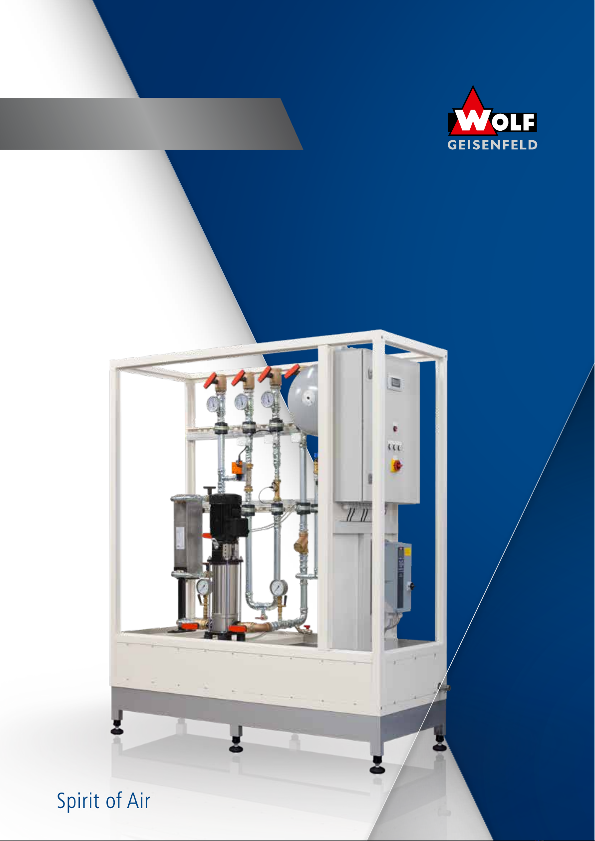
Wolf THERM CONNECT Instruction Manual

THERM CONNECT
WOLF WOLF run around coil systems
Operation & Maintenance
Translation of the original operating instruction

22
THERM CONNECT
WOLF run around coil systems
THERM CONNECT Zertifikate
WOLF run around coil systems
Quality Assurance
Declaration of incorporation

3
THERM CONNECT
WOLF run around coil systems
Content
1. Notes and regulations for the operator......................................4
2. Intended use ..........................................................4
3. Safety ...............................................................4
4. General information ....................................................6
04.01 Field of application .........................................................6
04.02 Accessories ...............................................................6
04.03 Protection measures taken ....................................................6
04.04 Material resistance to cleaning agents, disinfectants .................................6
04.05 Lightning protection ........................................................6
5. Storage, transport and assembly ..........................................7
05.01 Receipt of goods, transport damage .............................................7
05.02 Note on disposable packaging .................................................7
05.03 Storage and functional maintenance.............................................7
05.04 Construction site transport of air handling units and assemblies.........................8
05.05 Structure-borne sound decoupling .............................................10
05.06 Potential equalization ......................................................10
05.07 Medium-side connections ...................................................10
05.08 Drain-side connections......................................................10
05.09 Electrical connection .......................................................10
6. THERM-CONNECT basic .................................................11
06.01 General description ........................................................11
06.02 Control functions..........................................................11
06.03 Commissioning ...........................................................12
06.04 Faults and their elimination ..................................................12
06.05 Wiring diagram ...........................................................13
7. THERM-CONNECT defrost................................................14
07.01 General description ........................................................14
07.02 Frequency inverter display ...................................................15
07.03 Control functions..........................................................15
07.04 BMS connection ..........................................................16
07.05 Commissioning ...........................................................16
07.06 Faults and their elimination ..................................................18
07.07 Wiring diagram ...........................................................18
8. THERM-CONNECT magna ................................................19
08.01 General description ........................................................19
08.02 Display indication .........................................................20
08.03 Control functions..........................................................21
08.04 BMS connection ..........................................................23
08.05 Commissioning ...........................................................23
08.06 Faults and their elimination ..................................................24
08.07 Wiring diagram ...........................................................24
9. Maintenance .........................................................25
09.01 Warranty................................................................25
09.02 Electrical connections ......................................................25
10. Decommissioning, dismantling and disposal ................................25
10.01 Decommissioning .........................................................25
10.02 Recommissioning..........................................................25
10.03 Dismantling and disposal ....................................................26
11. Emergency..........................................................27
11.01 Fire fighting .............................................................27
11.02 Escaping harmful substances .................................................27

4
01 / 02 / 03 THERM CONNECT
WOLF run around coil systems
1. Notes and regulations for the operator
Meaning of the operating instructions
Read these operating and maintenance instructions carefully before installation and commissioning to ensure cor-
rect use! We would like to point out that these operating and maintenance instructions only apply to the unit and in
no case to the complete system! All unit-specific data such as order number, energy data, weight, dimensions, etc.
can be found either on the type plate of the respective unit component or in the technical order confirmation. These
operating and maintenance instructions are intended for safe working on and with the above-mentioned unit. They
contain safety instructions that must be observed as well as information that is necessary for trouble-free operation
of the unit. The operating and maintenance instructions must be kept with the unit. It must be ensured that all
persons who have to carry out activities on the unit can consult the operating and maintenance instructions at any
time. The operating and maintenance instructions must be kept for further use and must be passed on to every user
or end customer.
Duty of care of the operator
• The contractor or operator must ensure that the equipment and operating materials are operated and
maintained in accordance with the applicable rules and legal regulations.
• The operator is obliged to operate the unit only when it is in perfect condition.
• The unit may only be used for its intended purpose („area of use“).
• The safety devices must be checked regularly for proper functioning.
• The operating and maintenance instructions must always be kept available in a legible condition and complete
at the place of use of the unit.
• The personnel must be regularly instructed in all applicable questions of occupational safety and
environmental protection and must know the operating and maintenance instructions and in particular the
safety instructions contained therein.
• All safety and warning notices attached to the unit must not be removed and must remain legible.
2.Intended use
The intended use of these units is for heat recovery from the exhaust air stream of an air handling unit into the sup-
ply air stream. The idle pressure range must be operated in the range of 2.5 bar to 5 bar, depending on the specifi-
cations on the type plate of the unit. The exact idle pressure is specified on the type plate of the respective system.
Deviations require prior agreement or approval by the manufacturer. Any other use or use beyond this is considered
improper. The manufacturer is not liable for any damage resulting from this.
Before commissioning the THERM-CONNECT, the hydraulic system must be completely filled to the idle pressure
indicated on the type plate and vented. For this purpose, on-site air vents must be provided and the system must
be vented at the pump. If the pump is operated without sufficient filling with water-glycol mixture, damage to the
pump may occur!
3. Safety
The qualified personnel responsible for installation, commissioning, maintenance, troubleshooting and decommis-
sioning must be instructed to observe these operating instructions before starting work. All persons who carry out
an activity on this device must have read the operating and maintenance instructions. Non-observance of the oper-
ating instructions can endanger the persons entrusted with the work as well as cause malfunctions of the device.
Attention!
Activities on the air handling unit may only be started or carried out after the following functions have been
ensured:
After completion of the work, start up the plant according to >> Commissioning - Test run <<!
• Repair switches attached to the unit are connected
in the control circuit of the air handling unit.
• All poles of the power supply are voltage-free.
• Power-operated, rotating parts are secured against
restarting (repair switch can be shut off).
• Rotating parts are at standstill
• Device components have cooled down to normal
ambient temperatures (room temperature)

5
03 THERM CONNECT
WOLF run around coil systems
Attention!
Only qualified personnel may work on electrical components. The local Energy Supply Companies (german: EVU)
regulations and Association of Electrical, Electronic & Information Technologies (german: VDE) regulations must be
observed.
No changes or additions may be made to the unit, otherwise the manufacturer’s declaration of conformity will
become invalid!The WRG equipment can be a life-threatening source of danger due to rotating machine parts and
the risk of electric shock. Failure to observe the following safety instructions will result in DANGER FROM ELECTRI-
CAL SHOCK.
• The equipment contains high voltage capacitors that require a period of time to discharge after the main
power supply is interrupted.
• Make sure the hydraulic unit is disconnected from the power supply before performing any work.
Wait at least three minutes for the inverter to discharge to a safe voltage.
• Always disconnect the inverter from the circuit under test before performing a high voltage resistance test
on that circuit.
Symbols:
Opposite symbol is indicated in the operating instruc-
tions at any place where in case of non-observance
• there is danger to life and limb of persons
• damages of the machine can occur.
Opposite symbol is indicated in the operating
instructions at any place where there is danger
from electric components.
You find this symbol anywhere in these operating
instructions wherever there is a risk or need for incre-
ased protective measures due to areas at risk from
explosions.
You will find this symbol anywhere in these operating
instructions where there is a crushing hazard.
You will find this symbol anywhere in these operating
instructions where there is a suspended load hazard.
Warning against harmful and irritant substances
Opposite symbol in the operating instructions indicates
guidelines or cross-references which are important for
the operation of the RLT-plant.
Opposite symbol in the operating instructions indi-
cates information or application tips.
You will see the adjacent symbol anywhere, where
for example a risk of ignition can arise as a result of
electrostatic charge. The operator must earth (equi-
potential bonding) the entire unit according to state
of the art in order to prevent electrostatic charging.

6
04 THERM CONNECT
WOLF run around coil systems
4. General Information
04.01 Field of application
The area of application of the THERM-CONNECT unit supplied is for hydraulic heat recovery in air handling units.
Exact data can be taken from the order confirmation, in particular the technical unit design.
04.02 Accessories
The manufacturer offers or supplies units according to tenders from external designers of the entire air handling
unit. As a rule, this is only a part of the entire air handling system. Since the delivery is made only through special-
ized companies, certain accessories such as:
• Piping
• Insulation of piping and components
• High efficiency run around coils
• Complete regulation, control, power electrics
can be provided by the customer. In the technical design, reference is made to accessories provided by the customer.
Safety-relevant accessories must be installed by the specialist company before the first test run.
04.03 Protection measures taken
As a rule, our devices are equipped with the device-related safety measures. The repair switches are to be secured
against being switched on again during maintenance (repair switch can be shut off).
04.04 Material resistance to cleaning agents, disinfectants
For wipe disinfection of the inner surfaces of our air handling units in design
• Hot-dip galvanized
• Stainless steel (1. 4301)
• Aluminum (AlMg)
all commercially available disinfectants can be used.
We recommend disinfectants based on formaldehyde, whereby the information on the manufacturer’s safety data
sheets, with regard to
• material compatibility
• processing
must be observed.
04.05 Lightning protection
According to VDE 0185 T1 (VDE: Association of Electrical, Electronic & Information Technologies), a professional
lightning protection system must be installed on roof control centers.

7
05 THERM CONNECT
WOLF run around coil systems
5. Storage, Transport and Assembly
05.01 Receipt of goods, transport damage
Unpack the goods in the presence of the driver and check for completeness and damage using our delivery bill.
Transport damage must be acknowledged by the forwarder! (date and signature)
A subsequent claim will be rejected by the forwarding insurers.
05.02 Note on disposable packaging
This is purely transport packaging. It has been quantitatively reduced to the indispensable minimum in order to be
able to transport and unload the high-quality parts without damage.
The material is fully recyclable and can therefore be recycled.
The disposal costs are borne by the recipient of the goods.
Alternatively, it is possible to return the packaging material to us. The costs for the return transport are to be borne
by the customer of the goods. Please note that the packaging material must not be contaminated and must be
delivered separately according to groups.
05.03 Storage and functional maintenance
If parts are packed in foil, this must be removed immediately after delivery. Foils promote the formation of conden-
sation water and thus oxidation phenomena, especially on hot-dip galvanized material.
In the case of sendzimir-galvanized components, corrosion is possible at the cut edges. A reddish or whitish discol-
oration of the cut edge alone is not a sign of problematic corrosion. The corrosion protection is still guaranteed and
does not represent a reduction in its quality or a reason for complaint.
All device components and parts must be stored in such a way that impairments, damage due to contamination,
condensation, weathering or external influences are excluded. In case of storage, standstill or delayed commission-
ing (standstill longer than 3 months!), the belts of belt-driven components must be slackened. Rotating and rotating
components such as fans, motors, pumps, WRG rotors, actuators and louver dampers must be moved and rotated
monthly. In addition, the following measures should be observed:
• Remove foils
• Store units temporarily in a dry and dust-free place protected from the weather.
• Close device openings so that no impurities (dust, vermin) can penetrate.
• Avoid condensation
• Ensure functional integrity of the components and built-in parts
• Observe additional maintenance and operating instructions of the component manufacturers
The units must also be carefully protected from contamination during installation.
Maximum permissible storage period or downtime for:
Frequency converters, EC controllers, motors with integrated controllers.
Reforming of DC link capacitors
The maximum permissible storage period or the downtime without mains voltage depends in particular on the
electrolytic capacitors, since the dielectric in the capacitor degrades and the electrolyte evaporates.
Depending on the duration without supply with mains voltage, before applying the full mains voltage a the internal
capacitors before applying the full mains voltage.
Period without mains voltage Measure before commissioning
less than 1 year none
1-2 years connect device to mains for 1 hour without release
longer than 2 years reformatting (without enable) via adjustable supply voltage
1. 30% of mains voltage for 1 hour
2. for 1 hour 60% of the mains voltage
3. for 2 hours 85% of the mains voltage
4. for 3 hours 100% of the mains voltage
Mains voltage: Technical data of the respective device,
for wide voltage range = upper value of the mains voltage specification.

8
05 THERM CONNECT
WOLF run around coil systems
05.04 Construction site transport of air handling units and assemblies
Caution!
Serious personal injury or property damage may result from falling loads if the safety instructions are not observed.
Use and observe the safety instructions for the means of transport, lifting gear and approved lifting gear (according
to BGV D6, Regulations of the employers’ liability insurance association).
Do not stand under suspended loads!
Units without transport device: When transporting with a forklift or rollers, leave the transport pallet under the air
handling unit. When transporting with a forklift, ensure that the forks extend over the full width of the housing.
Frame must rest on forks on both sides.
The unit components may only be transported in the installed position. They must not be overturned or rotated in
the longitudinal axis, otherwise damage may occur to installed parts (e.g. fan vibration dampers shear off).
05.04.01 Fastening the load suspension brackets
Only the load suspension brackets specified or supplied
by the factory may be used to attach the suspension
ropes to the unit.
Attention! The use of the load suspension brackets
is only permitted for one device mounting!
The brackets must not be used for several devices, as pos-
sible hairline cracks could impair safety.
The load suspension brackets must be mounted using
hexagonal bolts DIN 933 M16 x 55 mm - 8.8 for stand-
ard design or hexagonal bolts DIN 933 M16 x 105 mm
- 8.8 for weatherproof design and washers 6.0 mm thick
with a minimum screw-in depth of 35 mm to ensure the
load capacity of the load suspension brackets.
The thread in the corner connector must not be dirty or
damaged.
For weatherproof units, use the spacer sleeves specified by the factory or supplied with the unit.
To fasten, align the lugs to the center (see illustration) and hand-tighten.
• Load suspension brackets with missing markings must not be used.
• Modifications and repairs, in particular welding, are not permitted.
• Use for or of other manufacturers’ products is not permitted.

9
05 THERM CONNECT
WOLF run around coil systems
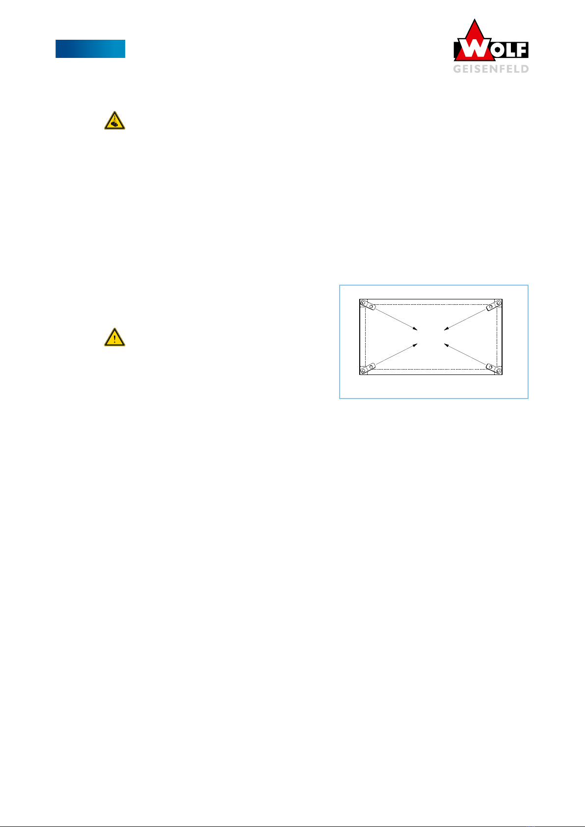
05.04.02 Attachment to lifting devices
Attachment to lifting devices must be carried out in accordance with the specifications in these operating instruc-
tions.
For fastening the suspension ropes or chains to the load suspension bracket, fastening elements appropriate to the load,
e.g. shackles, must be used! For crane transport, all applicable safety regulations according to DGUV regulation 52 Cranes
and DGUV 500 chapter 2.8 must be observed (DGUV german: German Statutory Accident Insurance).
Attention! The maximum load capacity per delivery unit incl. dead weight of the lifting aids must not be exceeded!
Exceeding the load capacity may result in damage to the delivery unit. There is a danger to life.
WK-com type max. load capacity / delivery unit max. load capacity / corner connector
N, N-W, H, H-W 2.500 kg 625 kg
S, S-W 3.000 kg 750 kg
When unloading, lifting and assembling, do not lift several equipment units together. Lift units with more than 4
lifting lugs only with a crane traverse.
The rope angle (S) must not exceed 60°.
The angle of inclination (A) must not exceed 30°.
The arrangement and dimensioning of the lifting lugs refers to a rope angle of 60° (corresponds to an angle of incli-
nation of 30°).
Larger rope or inclination angles cause an overload of the lifting straps and lead to damage to the device.
The length of the transport chain or ropes must at least correspond to the distance between the lifting straps.
Please take the prescribed values from the table “05.04.03 Standard values for attachment to lifting devices”.
The values in the table refer to a rope angle of 60° (= angle of inclination 30°).
05.04.03 Standard values for fastening to lifting devices
L = length of the module
width of the module H = hook height K = chain length
6,00 m 3,00 m 5,81 m 6,71 m
6,00 m 1,65 m 5,40 m 6,22 m
6,00 m 1,00 m 5,30 m 6,08 m
5,00 m 3,00 m 5,06 m 5,84 m
5,00 m 1,65 m 4,56 m 5,27 m
5,00 m 1,00 m 4,41 m 5,09 m
4,00 m 3,00 m 4,33 m 5,00 m
4,00 m 1,65 m 3,75 m 4,33 m
4,00 m 1,00 m 3,57 m 4,12 m
3,00 m 3,00 m 3,67 m 4,24 m
3,00 m 1,65 m 2,97 m 3,42 m
3,00 m 1,00 m 2,73 m 3,15 m
2,00 m 1,65 m 2,24 m 2,59 m
2,00 m 1,00 m 1,93 m 2,23 m
1,00 m 1,00 m 1,21 m 1,40 m

10
05 THERM CONNECT
WOLF run around coil systems
05.05 Structure-borne sound decoupling
For vibration isolation it is recommended to use suitable isolators.
05.06 Potential equalization
To avoid ignition hazards due to electrostatic charging, all electrically non-conductive connection points must be
bridged with potential equalization, e.g. elastic connections, decoupled frame, vibration damper, etc. All metal parts
of the device must be integrated into the local potential equalization measure. The base frames of the equipment
must be grounded according to the state of the art (foundation grounding).
05.07 Medium-side connections
The heat exchangers are connected with detachable connections. Care must be taken that access to other parts of
the unit is not obstructed by the connection lines (fan, filter, scrubber, etc.). When connecting the heat exchangers,
hold them with a pipe wrench.
The connections of the heat exchangers must not be loaded with expansion forces of the on-site supply lines. Use
expansion loops or compensators to absorb any forces that occur.
The flow of the heating or cooling system is connected to the exchanger on the air outlet side (counterflow principle).
Ensure that there is a venting and draining facility on site!
The connections on the THERM-CONNECT unit are provided with internal thread or flange. For the correct connec-
tion, the respective lines are provided with labels.
05.08 Drain-side connections
Depending on the unit type, the unit is equipped with a drain pan with ½” connection at the bottom or a glycol col-
lecting pan with 1” connection on the control cabinet side.
In the case of a drain pan, a collection device for the water-glycol mixture must be provided on site (retention
device for glycol-water mixture according to VAUwS , german: Directive on Installations for Handling Substances
Hazardous to Water!). The drain pan in the THERM-CONNECT unit provides a controlled discharge of leakages into
the drain.
If the unit is equipped with a drain pan, it offers sufficient volume to collect the entire amount of leaking fluid in
the event of an accident. In this case, the drain can be closed with a stopcock or forwarded to a collection device
provided by the customer
When installing the THERM-CONNECT unit in the unit, a suitable siphon must be provided at the drain!
05.09 Electrical connection
Attention!
During commissioning and maintenance, all terminal points of the electrical system must also be tightened.
EMC directives and radio interference suppression levels must be taken into account. For mains bypass circuits, the
relevant regulations according to VDE (Energy Supply Companies) and EVU (Association of Electrical, Electronic &
Information Technologies) for star-delta starting or direct starting must be observed. The connection guidelines of
the manufacturer must be observed!
The cross-section of the ground cable must be at least 10 mm², or two separately laid ground cables connected in
accordance with DIN EN 50178 or IEC 61800-5-1 must be used. Always follow the national and local regulations on
cable cross-section.
Commissioning: The operating instructions of the frequency inverter must be observed during commissioning. The
setting values of the frequency converter must be logged.
Caution:
Touching electrical components can be life-threatening even after disconnection from the power supply. Wait at
least 15 minutes.
Caution: The electrical connections as well as the wiring must be carried out by a qualified electrician. The applica-
ble standards must be observed.

11
06 THERM CONNECT basic
WOLF run around coil systems
6. THERM-CONNECT basic
06.01 General description
The high efficiency run around coil system consists of two heat exchangers with a high counterflow ratio and a
series connection of the individual heat transfer stages.
The heat is transferred via an intermediate medium consisting of a water-glycol mixture between the exhaust air coil
and the outdoor air coils.
The brine mass flow is controlled by the three-way control ball valve depending on the power demand of the BMS.
In addition, frost protection can be controlled via this using a temperature sensor provided by the customer. This
allows the brine mass flow to be routed past the supply air coil in order to prevent ice formation on the coil. The
pump is controlled digitally by switching the operating voltage through an on-site contactor.
VL
RL
M
P
AB
B
A
Outside air
Exhaust air
Supply Air
Exhaust air
Expansion tank
A3
Z2 Z1
VL
RL
A4
Drainage and venting on site
Liter limit
WOLF Geisenfeld
Liters
DN
Transfer points
Z1 "IG
Z2 "IG
A3 " IG
A4 " IG
Rotary valve
Fabr. Belimo
type:
High pressure pump
Fabr. EBARA
DN
Änderung
Qualitätsmanagement
DIN EN ISO 9001
zertifiziert nach
Zust. NameDatum
Norm
Gepr.
Bearb.
2018 Datum
Hochleistungs-KVS
Prinzipschema
Änderungen vorbehalten
MAßSTAB
AB-
Kom. THERM-CONNECT basic
Maßstab
Name
Bl
Blatt
GmbH & Co.KG
WOLF Anlagen-Technik
85290 Geisenfeld
Münchener Str. 54
Fax.08452 / 99-250
Tel. 08452 / 99-0
Diese Zeichnung darf ohne unsere ausdrückliche Genehmigung weder vervielfältigt, noch dritten Personen oder Konkurrenzfirmen im Original oder
als Kopie ausgehändigt werden. Eigentums- und Urheberrecht vorbehalten.
DN
19.01.2019 F.Franz
Safety valve
6 bar
1
2" Connection
for
on-site frost
protection
06.02 Control functions
• External release Pump On
• Pump starts up to set frequency.
• External power signal ( 0-10V DC) directly controls the three-way valve for power control.
• External enable pump off
• The system stops
Frost protection control:
An on-site temperature sensor for frost protection control can be integrated via the existing ½” connection in the
exhaust air flow.

12
06 THERM CONNECT basic
WOLF run around coil systems
06.03 Commissioning
06.03.01 Filling the system
Checking before filling the system
Before filling the hydraulic control group, check the following parameters
• Proper installation of all parts
• Vent valve installed at the highest point of piping
• Flow direction at valves, pumps, etc.
• Installation position of valves, etc.
• Connection of heaters, coolers in counterflow principle (otherwise considerable power losses will occur!)
• Tight fit of all connections (screwed connections, flanges, etc.)
• Smooth running of valves, slide valves, actuators
• Hydraulic lines must be flushed and cleaned
Attention! When filling and venting the system, there is a risk of injury due to
• Escaping pressure jet
• Scalding with hot heating media
• Burning in case of skin contact with antifreeze additives
Filling and bleeding
Fill hydraulic control group slowly - vent carefully. During the filling process, open the venting valve. During the fill-
ing process, check all connection points for leaks, eliminate them if necessary. After reaching the system pressure on
the medium side, close the venting valve.
Attention
When opening the venting device of the run around coil system, the plant must be switched off. Secure the main
switch! The liquids, e.g. water-glycol mixture (-20°C to 40°C), are under pressure and can thus escape abruptly.
Personal protective equipment such as suitable goggles and gloves must be worn or the manufacturer’s instructions
must be observed.
06.03.02 First test run
Tighten all clamping points of the electrical system!
During commissioning, ensure that the system is not operated beyond the limits specified in the design data.
Improper operation will result in damage to the unit for which we do not accept any warranty! During commission-
ing, as well as for the subsequent operation of the air handling unit, the information signs on the air handling unit
must be observed!
Switch on the circulation pump, check the direction of rotation, reverse the direction of rotation electrically if nec-
essary. Run the circulation pump to remove residual air from the control group. Check system pressure, top up if
necessary and vent again.
06.04 Faults and their elimination
All malfunctions such as the pump PTC thermistor, danger of frost or too low brine pressure must be evaluated via
the on-site control system.

13
06 THERM CONNECT basic
WOLF run around coil systems
06.05 Wiring diagram
Valve actuator
Three-phase motor

14
07 THERM CONNECT defrost
WOLF run around coil systems
7. THERM-CONNECT defrost
07.01 General description
The high efficiency run around coil system consists of two heat exchangers with a high counterflow ratio and a
series connection of the individual heat transfer stages.
The heat is transferred via an intermediate medium consisting of a water-glycol mixture between the exhaust air coil
and the outdoor air coil.
The brine mass flow is controlled by the frequency converter depending on the power demand of the BMS.
The power and frost protection control is also performed by the three-way mixing valve with high control accuracy.
This allows the brine mass flow to bypass the supply air register to prevent ice formation on the register.
All parameters are already programmed on the frequency converter. Since the pumps are designed separately for
each system, the flow rate must be adapted to the particular system. For this purpose, the flow rate is read off the
integrated TacoSetter and set as the maximum setpoint on the frequency inverter
„07.05.03 Setting the maximum
flow rate“ on page 17
For this purpose, the system must be filled up to operating pressure and completely vent-
ed to avoid damage to the pump.
VL
RL
M
PP
FU
AB
B
A
Outside air
Exhaust Air
Supply air
Exhaust Air
m³
A3
Z2 Z1
T
VL
RL
A4
T
Drainage and venting on site
Delivery limit
WOLF Geisenfeld
DN
Transfer points
Z1 "IG
Z2 "IG
A3 " IG
A4 " IG
Three-way valve
Fabr. Belimo
TacoSetter
Fabr. Taconova Bypass
High pressure pump
Fabr. EBARA
EVMSG
Frequency converter
Fabr. Danfoss
FC102
DN
Änderung
Qualitätsmanagement
DIN EN ISO 9001
zertifiziert nach
Zust. NameDatum
Norm
Gepr.
Bearb.
2018 Datum
Hochleistungs-KVS
Prinzipschema
Änderungen vorbehalten
MAßSTAB
AB-
Kom. THERM-CONNECT defrost
Maßstab
Name
Bl
Blatt
GmbH & Co.KG
WOLF Anlagen-Technik
85290 Geisenfeld
Münchener Str. 54
Fax.08452 / 99-250
Tel. 08452 / 99-0
Diese Zeichnung darf ohne unsere ausdrückliche Genehmigung weder vervielfältigt, noch dritten Personen oder Konkurrenzfirmen im Original oder
als Kopie ausgehändigt werden. Eigentums- und Urheberrecht vorbehalten.
DN
19.01.2019 F.Franz
On-site BMS:
from external:
1x 1 x enable contact as normally open contact
1x power request 1-10 V DC
to external:
1x operating message portfree normally open contact for 230 V
1x collective fault signal port-free NC contact for 230 V
Safety valve
Fabr. SYR 2115
Verriegelung min.
Fabr. Fema DWR
Expansion tank
Fabr. Reflex S
21.10.2019 F.Franz

15
07 THERM CONNECT defrost
WOLF run around coil systems
07.02 Frequency inverter display
The most important system parameters can be read directly from the display of the frequency inverter:
Setpoint input Control signal valve
Frequency pump
Temperature of exhaust
air flow
Return air temperature
07.03 Control functions
• External enable On
• The system starts up to the minimum frequency. The valve closes as long as no external power signal (
0-10V DC) is present.
• External power signal ( 0-10V DC) from the higher-level temperature control sequence
• The setpoint of the circulating water-glycol quantity is determined depending on the ext. power signal, the
maximum water quantity and the frost protection temperature value.
• The volume flow is controlled in the internal control sequence valve and speed control of the recirculation
water pump via frequency converter.
• External release Off
• The system stops
Periodic pump run:
To prevent the pump from getting stuck, even if there is no demand from the control system, a periodic pump run is
performed once a week. During this, the pump runs for 10 minutes at 50% power demand.
Frost protection control:
The integrated frost protection control is set to the limit value -1°C at the factory. Experience has shown that this
value is sufficient to prevent icing of the register and at the same time to operate the heat recovery as efficiently as
possible.
If this frost protection is not sufficient, a second limit value at -2.5°C is stored. If the temperature falls below this
limit, the system is switched off and locked.

16
07 THERM CONNECT defrost
WOLF run around coil systems
07.04 BMS connection
Control from external AHU control
1 x release contacts from external AHU control cabinet as normally open contact
1 x power request 0-10 V DC
Contacts to external AHU control
1 x operating message potential free normally open contact for 230 V
1 x collective fault signal floating NC contact for 230 V
07.05 Commissioning
07.05.01 Filling the system
Check before filling the system
Before filling the hydraulic control group, check the following parameters
• Proper installation of all parts
• Vent valve installed at the highest point of piping
• Flow direction at valves, pumps, etc.
• Installation position of valves, etc.
• Connection of heaters, coolers in counterflow principle (otherwise considerable power losses will occur!)
• Tight fit of all connections (screwed connections, flanges, etc.)
• Smooth running of valves, slide valves, actuators
• Hydraulic lines must be flushed and cleaned
Attention! When filling and venting the system, there is a risk of injury due to
• Escaping pressure jet
• Scalding with hot heating media
• Burning in case of skin contact with antifreeze additives
Filling and bleeding
Fill hydraulic control group slowly - vent carefully. During the filling process, open the venting valve. During the fill-
ing process, check all connection points for leaks, eliminate them if necessary. After reaching the system pressure on
the medium side, close the venting valve.
Attention
When opening the venting device of the run around coil system, the plant must be switched off. Secure the main
switch! The liquids, e.g. water-glycol mixture (-20°C to 40°C), are under pressure and can thus escape abruptly.
Personal protective equipment such as suitable goggles and gloves must be worn or the manufacturer’s instructions
followed.
07.05.02 First test run
Tighten all clamping points of the electrical system!
During commissioning, ensure that the plant is not operated beyond the limits specified in the design data.
Improper operation will result in damage to the unit for which we cannot accept any liability! During commission-
ing, as well as for the subsequent operation of the AHU, the information signs on the AHU must be observed!

17
07 THERM CONNECT defrost
WOLF run around coil systems
Switch on recirculation pump, check direction of rotation, reverse direction of rotation electrically if necessary. Run
the recirculation pump to remove residual air from the control group. Check system pressure, top up if necessary
and vent again.
07.05.03 Setting the maximum flow rate
• Start the pump on the frequency converter via “Hand On“
• Use the arrow keys to adjust the setpoint between 20 Hz and 45 Hz
• Adjust the setpoint so that the nominal flow rate (see type plate of the hydraulic unit) is adjusted at the
taco setter.
• Enter the required frequency in the table below.
• Stop the pump at the frequency converter via “Off
• On the frequency inverter, navigate via the “Main Menu” to the item 0-11 Program block and select [1] Block 1.
• Then navigate to 3-03 Maximum Reference and enter the previously determined setpoint using the arrow
keys. Enter the same value also under 6-15 Terminal 53 High Ref./Feedb. Value
• Finally, the value [9] Active block must be set again under 0-11 Program block and the main display reacti-
vated via “Status”.
• Now the plant can be activated again via “Auto on”.
Menu Menu designation Setting
Display indication
Unit
0-11 Program block Activated
parameter block
[1] Block 1
3-03 Max. Setpoint Max. Output
frequency
______ Hz
6-15 Terminal 53 Scal. Max. setpoint/actual
value
signal scaling ______ Hz
0-11 Program block Activated
parameter block
[9] Active block

18
07 THERM CONNECT defrost
WOLF run around coil systems
07.06 Faults and their elimination
07.06.01 Min. pressure switch-off
If the pressure on the suction side of the system falls below the standard 1.5 bar, the system must be switched off
to protect the components of the pump. When the minimum pressure limitation is triggered, the frequency inverter
locks the system and the alarm lamp on the display lights up. In order to be able to acknowledge the fault, the
rest pressure of the system must be refilled to the pressure value specified on the type plate. The fault can then be
acknowledged via the reset button on the FI display.
07.06.02 Further fault messages
All other fault messages, such as the PTC thermistor of the pump or internal fault messages of the frequency invert-
er, are displayed as messages on the FI display. These can be acknowledged via the reset key after they have been
rectified.
All fault messages are forwarded to the BMS as a collective fault message.
07.07 Wiring diagram
Three-phase motor
on-site supply
Valve actuator
Main switch in FI (option)
Supply line
Fault Operation
Temperatur sensor Temperatur sensor
Return exhaust air
Pressure sensor
ow exhaust air
release by
customer

19
08 THERM CONNECT magna
WOLF run around coil systems
8. THERM-CONNECT magna
08.01 General description
The high efficiency run around coil system consists of two heat exchangers with a high counterflow ratio and a
series connection of the individual heat transfer stages.
The heat is transferred via an intermediate medium consisting of a water-glycol mixture between the exhaust air coil
and the outdoor air coil.
The brine mass flow is controlled by the integrated control system depending on the power requirement of the BMS,
the air volume flow in supply air and exhaust air and the temperature conditions in the system.
The power and frost protection control is also carried out via the three-way mixing valve with high control accuracy.
This allows the brine mass flow to bypass the supply air register to prevent ice formation on the register.
Optional extensions can be used to integrate an adiabatic exhaust air humidifier, the feeding of external additional
energy into the run around coil circuit, an accurate capacity determination with monthly data backup, a reheater for
dehumidification cold recovery or a redundant double pump for fail-safe operation.
Since the pumps are designed separately for each system, the flow rate must be adapted to the respective system.
This is done during commissioning of the system by a trained technician from WOLF Geisenfeld.
M
P
AB
B
A
Locking min.
Expansion tank
m³
T
T
F.FRANZ
Änderung
Qualitätsmanagement
DIN EN ISO 9001
zertifiziert nach
Zust. NameDatum
12.12.18
Norm
Gepr.
Bearb.
2013 Datum
Hochleistungs-KVS
Prinzipschema
Änderungen vorbehalten
MAßSTAB
AB-
Kom.
Maßstab
Name
Bl
Blatt
GmbH & Co.KG
WOLF Anlagen-Technik
85290 Geisenfeld
München er Str. 54
Fax.08452 / 99-250
Tel. 08452 / 99-0
Diese Zeichnung darf ohne unsere ausdrückliche Genehmigung weder vervielfältigt, noch dritten Personen oder Konkurrenzfirmen im Original oder
als Kopie ausgehändigt werden. Eigentums- und Urheberrecht vorbehalten.
Safety valve 8bar
A1
Z2 Z1
A2
supply limit
WOLF Geisenfeld
H2H1
21
T T
P
P
FU
K2K1
Drainage and venting on site
...
T
T
T
External
heat supply
External
cooling supply
FU
VL
RL
Outside air Supply air
TTZULV
DN ..
Cooler
Filter preheater Heater
ABL
V
Exhaust air
Exhaust air
VL
RL
T
DN ...
T
adiabatic
Run around cooler humidification
optional
optional
optional
optional
optional
optional
M
AB
B
A
Reheater
N1 N2
external connections
supply air register
- Z1
- Z2
exhaust air register
- A1
- A2
Reheater
- N1
- N2
Heating supply
- H1
- H2
Cooling supply
- K1
- K2

20
08 THERM CONNECT magna
WOLF run around coil systems
08.02 Display indication
In the main overview of the display the respective requirements of the superordinate control can be read. These are
divided into the heating and cooling requirements.
Operating elements
The operating elements and their functions are:
Pos. Designation Functions
1Display Display of menus, objects, parameters, parameter values, commands, etc.
2Up / Down • navigating through menus
• changing parameter values
3Confirm key • selecting menus
• accepting the changed value
4Cancel key • return to parent menu
• discard changed value
5Alarm key LED • Off: No alarm
• Flashing: Pending alarm
• On continuously: Pending acknowledged alarm
Press key:
• Go to last alarm
• Jump to alarm list (display of pending alarms and alarm history)
• Jump to alarm history
• Jump to alarm settings
• Acknowledge and reset alarms in the alarm list or alarm history.
6Info key LED • Off: Unit Off
• Green: Unit On
• Orange: Manual operation / simulation
• Orange-Red flashing: Manual operation and pending alarm
• Red: Pending alarm
1
26
25
34
Table of contents
Other Wolf Industrial Equipment manuals