wolfappliance.com | 5
Preparation
Before moving the range, protect any finished flooring and
secure the oven door closed to prevent damage.
OVEN DOOR REMOVAL
To lighten the load or to fit through a doorway, the oven
door can be removed. Remove only if necessary. Door
removal should be done only by a certified installer or
service technician. Do not lift or carry the oven door by the
door handle.
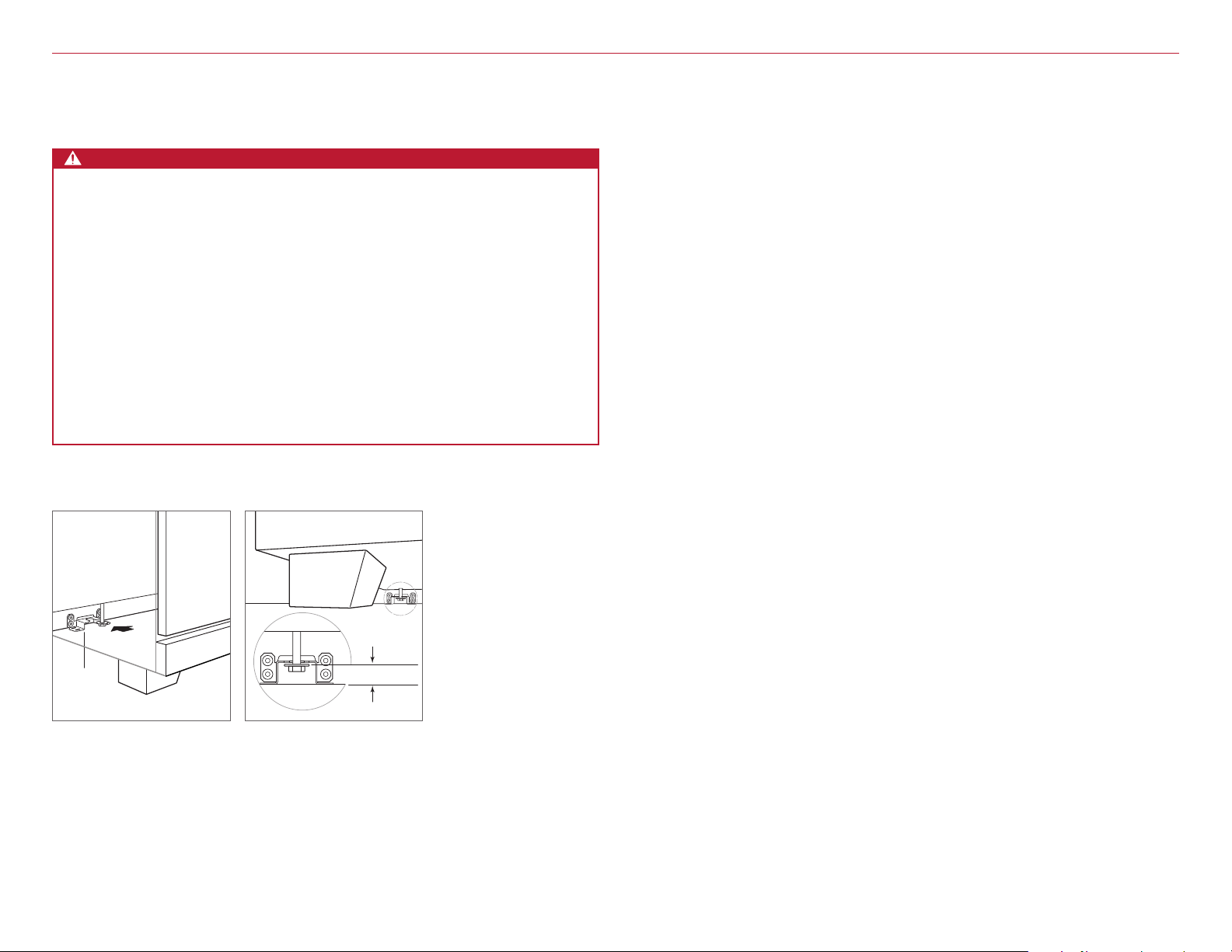
To remove, open the door completely. Rotate both hinge
locks forward to the open position, remove the screw
closest to the hinge on both sides of the door, and pull the
door forward. Refer to the illustration below.
To reinstall, slide the door onto the hinges. Rotate the
hinge locks back completely and install the screws.
Placement
The range has rear casters which allow for easy movement
by lifting the front of the unit. Do not lift or carry the range
by the oven door handle.
Use an appliance dolly to move the range near the open-
ing. Place the appliance dolly on the side or back to pre-
vent damage. Remove and recycle packing materials. Do
not discard the anti-tip bracket supplied with the range.
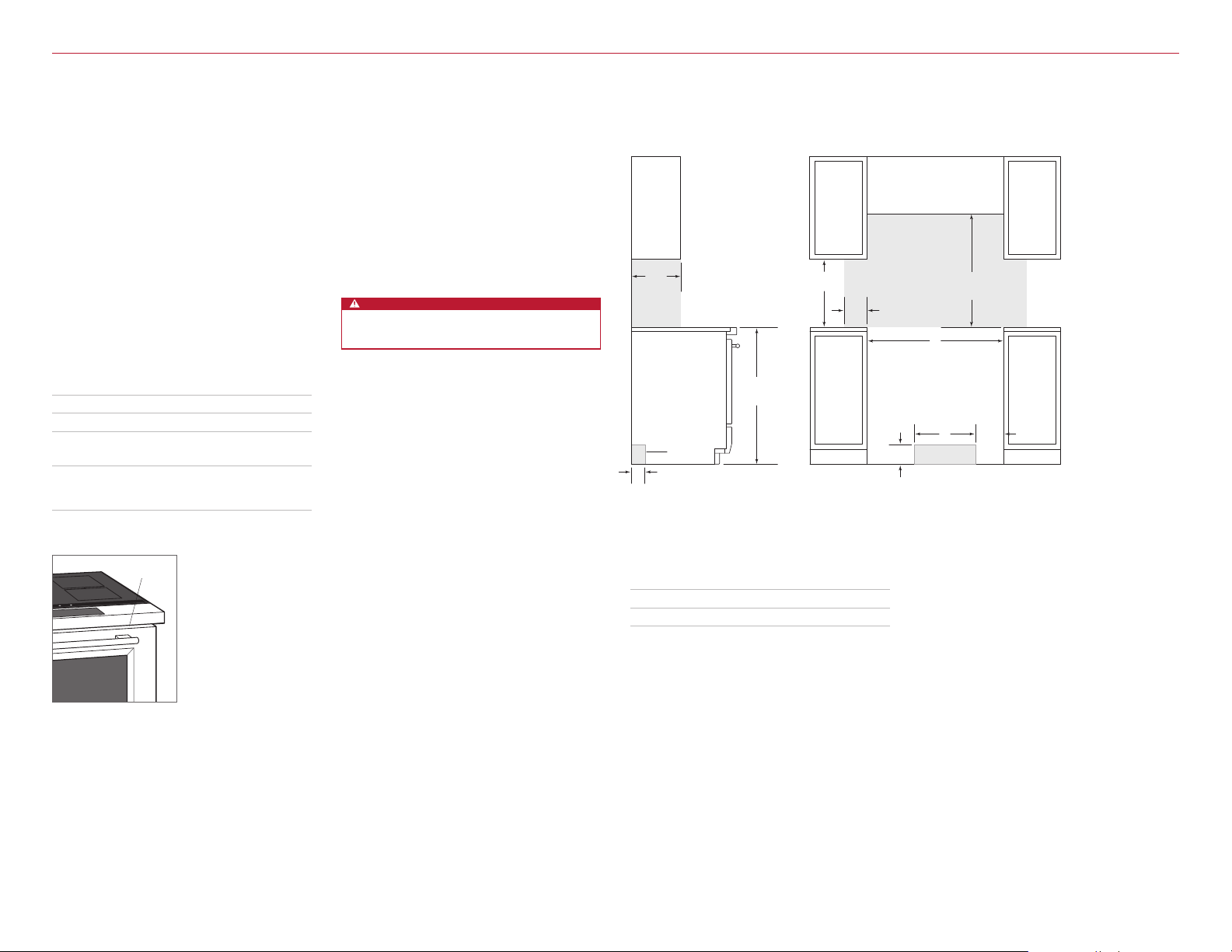
Leveling
Raise the range to its desired height by adjusting the front
legs and rear casters. Use a ⁄" socket to adjust the rear
casters. The front legs can be adjusted by rotating the leg
clockwise to raise and counterclockwise to lower.
HINGE
LOCK
SCREW
Oven door removal
Installation
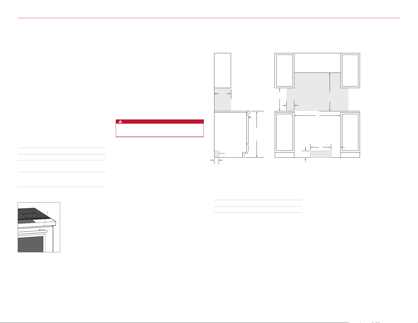
Anti-Tip Bracket
To prevent the range from tipping forward, the anti-tip
bracket must be installed. To ensure the anti-tip bolt
engages the bracket, refer to the illustration below to
determine proper placement.
INSTALL BRACKET
Drywall application: After properly positioning the anti-tip
bracket, mark the holes, then use a Phillips screwdriver
or a low rpm power drill to drive the wall anchor into the
surface of the wallboard until flush. Pre-drill the holes if
needed. For hard wallboard or double-board construc-
tion, use a ⁄" drill bit. For solid plaster, use a ⁄" drill bit.
Use the provided #8 screws and flat washers to fasten the
bracket to the wall.
Wood floor application: After properly positioning the anti-
tip bracket, drill 5 mm pilot holes through the floor. Use
the provided #12 screws and flat washers to secure the
bracket to the floor.
Concrete floor application: After properly positioning
the anti-tip bracket, drill 10 mm holes into the concrete
a minimum of 38 mm deep. Use the provided ⁄" wedge
anchors to secure the bracket to the floor.
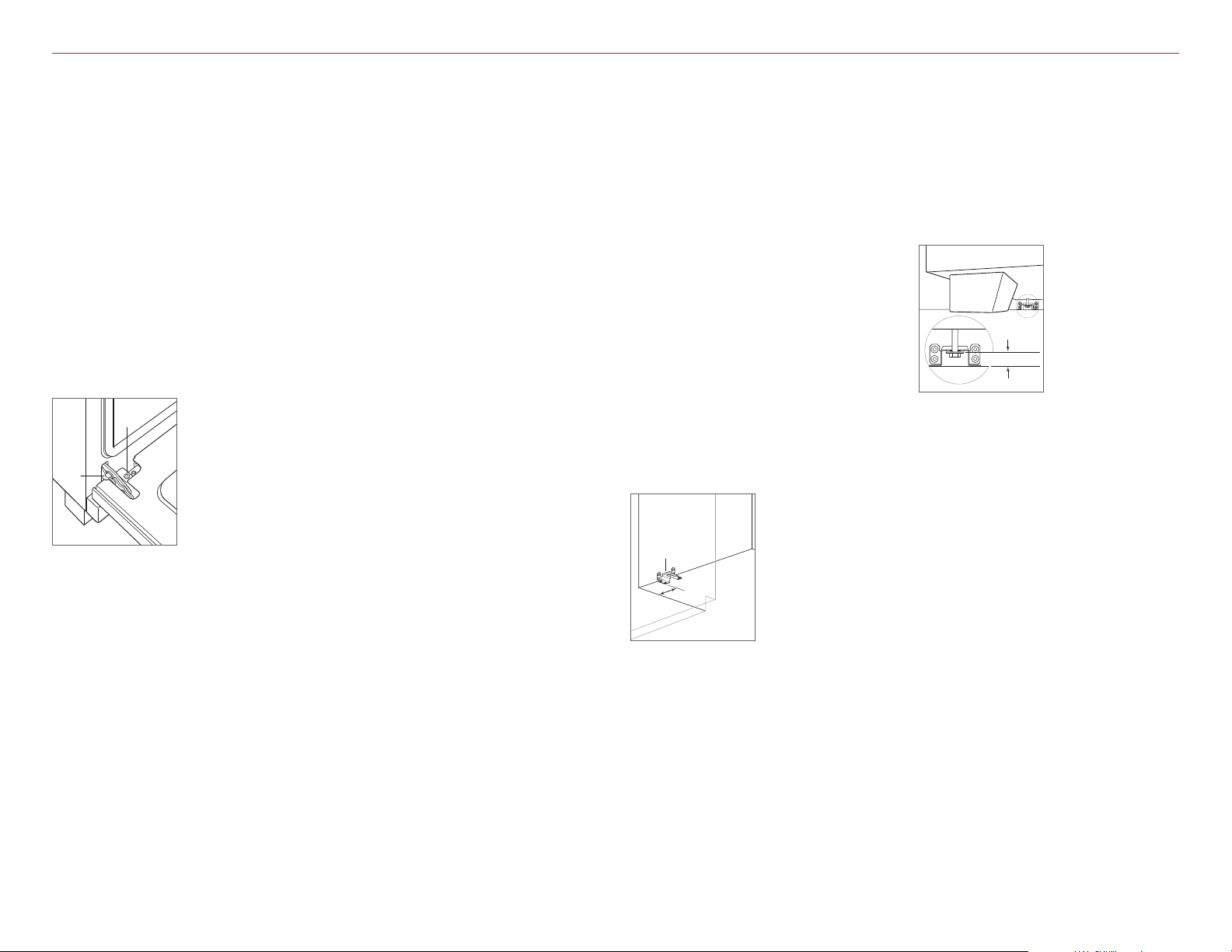
ANTI-TIP BOLT ADJUSTMENT
Once the bracket is secure, adjust the anti-tip bolt so the
top of the washer is 38 mm to 48 mm from the floor. Slide
the range into the opening and verify the anti-tip bolt is
engaged. Refer to the illustration below.
ANTI-TIP
BRACKET
159
mm
Anti-tip bracket location
38 – 48 mm
Anti-tip bolt engaged