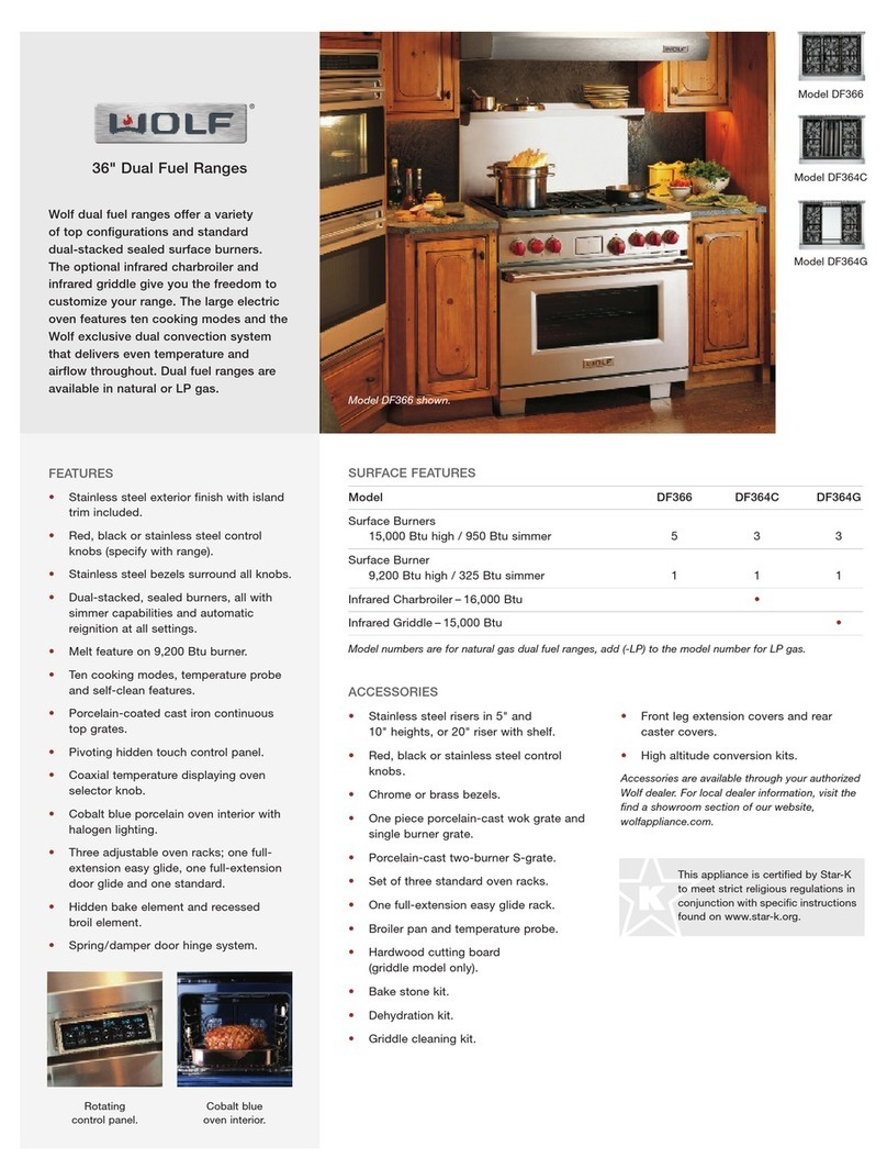
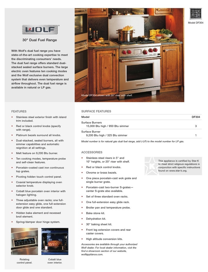
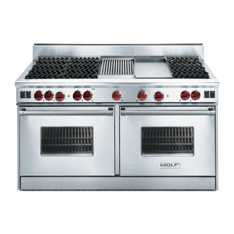
manuals.online logo
Brands
  1. Home
  2. •
  3. Brands
  4. •
  5. Wolf
  6. •
  7. Range
  8. •
  9. Wolf Induction Range Series User manual

Wolf Induction Range Series User manual

Induction Range (IR) Series
Component Removal
3-2
#827176 - Revision A.1 - December, 2016
COMPONENT REMOVAL
This section explains how to remove components from a Wolf Induction Range (IR) Series. Depending on which
component you are going to remove, you may have to remove other components first. Refer to the appropriate sec-
tion in this manual that explains how to remove those various components. When reassembling, just reverse the
steps that were used to remove the components.
NOTE: Before attempting to access or remove any components from a Wolf appliance, take note of the WARN-
INGS and CAUTIONS below.
•TO AVOID ELECTRIC SHOCK, POWER TO THE UNIT MUST BE DISCONNECTED WHENEVER SERVICING
AND/OR ACCESSING COMPONENTS.
•KEEP IN MIND THAT UNIT SURFACES AND COMPONENTS GET HOT DURING USE OF THE APPLIANCE.
•PULLING A UNIT FROM ITS INSTALLATION SHOULD ONLY BE PERFORMED BY A CERTIFIED SERVICE
TECHNICIAN OR INSTALLER.
•When working on the induction range and components, be careful when handling sheet metal parts. They
may have sharp edges.
Tools Needed
6-Lobe Torx type driver size T-15•
6-Lobe Torx type driver size T-20•
6-Lobe Torx type driver size T-25•
Phillips screw driver•
Small flat blade screw driver•
Flat blade screw driver•
Needle nose pliers•
Putty knife•
5/32” Allen wrench•
5/8” Box wrench•
Component Removal
Induction Range (IR) Series
3-3 #827176 - Revision A.1 - December, 2016
Induction Range
The induction range has a Induction Cooktop attached
to a Dual Fuel oven. This first section is components
that can be removed without pulling the unit from the
installation.
Skirt Removal
At the base of the unit is the skirt. The skirt shield is
attached to the back of the skirt.
To remove the skirt (See Figure 3-1):
Extract the two screws at the top of the skirt.1
The skirt is supported by two key slots at the bot-2
tom. Lift the skirt to remove it from the shoulder
screws.
Oven Door Adjustment
The oven door has two adjusting posts at the bottom of
the oven door. Adjusting the screw in or out raises or
lowers that side of the oven door, changing the space
between the top of the oven door and the bullnose.
To adjust the oven door (See Figure 3-2):
Remove the unit skirt.1
Use a 5/32” allen wrench to adjust the screw.2
Clockwise raises the door, and counterclockwise
lowers the door.
Oven Door Removal
The oven door uses a spring and damper system. Only
one hinge arm is spring loaded, which requires use of
the hinge pin for removal.
To remove the oven door, first remove the skirt, then
(See Figure 3-3):
Open the door to its fully opened position.1
Insert the hinge pin through hole in the spring2
loaded hinge.
Extract the screws from the top and bottom of the3
hinge retainer plate. The hinge retainer remains
with the door.
Close the oven door to about a 60° angle from the4
horizontal and lift up on the door while continuing to
pull the door away from the unit.
Figure 3-1. Shirt Removal
Figure 3-3. Door Removal
Hinge Pin
Hinge Retainer
Figure 3-2. Door Adjustment
Induction Range (IR) Series
Component Removal
3-4
#827176 - Revision A.1 - December, 2016
Door Skin Removal
The door skin and handle are attached to the liner
assembly by two screws below the logo, three screws
on the bottom of the door, and four screws at the top of
the liner assembly.
To remove the door skin, first remove the door, then
(See Figure 3-4):
Place tape around the logo and use a putty knife to1
peal the logo from the front of the door.
Extract the screws behind the logo.2
Extract the screws from the bottom of the door.3
Extract the screws from the top of the liner assem-4
bly.
Lift the door skin from the liner assembly.5
Hinge Removal
The hinges are attached to the liner assembly by two
screws at the bottom of the liner assembly, and a tab
on the liner assembly at the top of the hinge.
To remove a hinge, first remove the door skin, then
(See Figure 3-5):
Extract the screws at bottom of the liner assembly.1
Lift the bottom of the hinge up past the edge of the2
liner and disengage the hinge from the tab.
Remove the hinge from the liner assembly.3
Glass Pack Assembly Removal
The glass pack is inserted into the liner assembly and
has insulation and brackets around it to keep it in place.
To remove the glass pack assembly, first remove the
door skin, then (See Figure 3-6):
Extract screws from reinforcement bracket and1
remove the reinforcement bracket.
Extract the screws from the four glass pack retainer2
brackets, and remove them.
Extract the screws from the door baffle and remove3
the door baffle.
Remove the glass pack.4
Figure 3-5. Hinge Removal
Tab for Hinge
Figure 3-6. Glass Pack Removal
Reinforcement
Bracket
Glass Pack
Retainer Brackets
Door Baffle Glass Pack
Figure 3-4. Door Skin Removal
Component Removal
Induction Range (IR) Series
3-5 #827176 - Revision A.1 - December, 2016
Handle Removal
The handle bar is locked between the two handle
standoffs that are attached to the door skin.
To remove the handle, first remove the door skin, then
(See Figure 3-7):
Extract the screws from handle pad that pass1
through the door skin into the handle standoffs.
Remove the standoffs and handle bar.2
Gasket Removal
The oven gasket is a two part gasket with one part
around the top and the two sides of the cavity, and the
second part at the bottom of the oven cavity. The gas-
kets are attached to the oven face by a series of spring
pins.
To remove the gasket, first open the oven door, then
(See Figure 3-8):
Use needle nose pliers to compress the spring pins1
on the back of the gasket.
Remove the gasket.2
Rack Removal
There are three types of racks in the oven. The flat rack
which can be used in any position in the oven, the bent
rack, designed to be used in the lowest position and to
be pulled out on to the door, and the sliding rack which
rolls out on sliding rails.
To remove a rack, first open the oven door, then (Not
Shown):
Pull the rack forward until it stops.1
Lift the front of rack up and pull the rack from the2
oven.
Rack Guide Removal
To remove the rack guides, first remove the racks, then
(See Figure 3-9):
Lift the rack guide up.1
Pull the top of the rack guide toward the center of2
the oven, disengaging it from the shoulder screws.
Pull the rack guide forward from the oven.3
Figure 3-7. Handle Removal
Figure 3-8. Gasket Removal
Figure 3-9. Rack Guide Removal
•The rails on the sliding rack move by themselves.
Keep hands and fingers out of the line of travel.
Induction Range (IR) Series
Component Removal
3-6
#827176 - Revision A.1 - December, 2016
Halogen Bulb Removal
There are two halogen lamps in the oven cavity. There
is a pressed on glass lens that covers the bulb.
To remove the halogen bulb, first remove the rack guide
on the side of the oven where the halogen bulb needs
to be replaced, then (See Figure 3-10):
Use a flat bladed screw driver to remove the glass1
lens.
Use a clean, dry, oil free cloth to remove and install2
the new halogen bulb.
Convection Baffle Removal
The convection baffle covers the convection fans and
elements. It is attached to the back wall with screws.
To remove the convection baffle, first remove the rack
guides, then (See Figure 3-11):
Extract the screws above and below the convection1
baffle.
Remove the convection baffle from the oven cavity.2
Convection Element Removal
The convection element surrounds the convection fan
and is held in place with three screws.
To remove the convection element, first remove the
convection baffle, then (See Figure 3-12):
Extract the two top screws and one bottom screw1
from the convection element supports.
Tilt the bottom of the element up to pull the spade2
terminals with the wires attach through the back
wall.
Disconnect the wires from the convection element3
spade terminals.
Remove the convection element.4
Figure 3-11. Convection Baffle Removal
Figure 3-12. Convection Element Removal
Figure 3-10. Convection Baffle Removal
Component Removal
Induction Range (IR) Series
3-7 #827176 - Revision A.1 - December, 2016
Convection Fan Removal.
The convection fans are held in place with screws to
the back wall of the oven. The left fan has five screws
and the right fan has six screws so that the fans can
not be reversed.
To remove the convection fan, first remove the convec-
tion element, then (See Figure 3-13):
Extract the screws from the fan shroud.1
Remove the fan from the back wall.2
Disconnect the electrical wires from the fan.3
Remove the fan from the oven.4
Temperature Sensor Removal
The temperature sensor is attached to the back wall of
the oven.
To remove the temperature sensor, first remove the
oven racks, then (See Figure 3-14):
Extract the screws from the temperature sensor.1
Pull the temperature sensor into the oven cavity.2
Disconnect the wire harness.3
Remove the temperature sensor.4
Smoke Catalyst Removal
The smoke catalyst is located in the top of the oven
cavity.
To remove the smoke catalyst, first remove the oven
racks, then (See Figure 3-15):
Extract the screws from the smoke catalyst.1
Remove the smoke catalyst.2
Figure 3-13. Convection Fan Removal
Figure 3-14. Temperature Sensor Removal
Figure 3-15. Smoke Catalyst Removal
Induction Range (IR) Series
Component Removal
3-8
#827176 - Revision A.1 - December, 2016
Probe Cover Removal
The probe cover is on the right hand side of the oven
cavity.
To remove the probe cover, first remove the oven racks,
then (See Figure 3-16):
Lift the probe cover and use a 5/8” box wrench to1
remove the retaining nut.
Remove the probe cover.2
Broil Element Removal
The broil element and the broil element deflector are
attached to the ceiling of the oven cavity.
To remove the broil element, first remove the oven
racks, then (See Figure 3-17):
Extract the screws holding the broil element and1
broiler deflector pan to the ceiling of the oven.
Pull the broil element and broil deflector pan for-2
ward into the oven and disconnect the electrical
connectors.
Remove the broil element and broil deflector pan3
from the oven.
Remove the broil element from the broil deflector4
pan.
Bake Element Removal
The bake element is accessed from the front of the unit.
It sits in a tray that lowers down to remove the bake
element.
To remove the bake element, first remove the unit skirt,
then (See Figure 3-18):
Extract the screws from the tray assembly.1
Lower the front of the tray assembly and pull it for-2
ward from the unit.
Use a pair of Needle Nose pliers to disconnect the3
spade terminals from the bake element.
Lift the bake pan assembly from the tray assembly4
and pull it forward.
Remove the bake pan assembly from the unit.5
Figure 3-17. Broil Element Removal
Figure 3-18. Bake Element Removal
Figure 3-16. Prove Cover Removal
Component Removal
Induction Range (IR) Series
3-9 #827176 - Revision A.1 - December, 2016
Induction Range
The induction range has a Induction Cooktop attached
to a Dual Fuel oven. To access the majority of the com-
ponents the unit needs to be pulled from the installa-
tion, and the induction cooktop needs to be removed.
Induction Cooktop Removal
To remove the induction cooktop top, first remove the
unit from the installation, then (See Figure 3-19):
Extract the six screws from the back of the island1
trim.
Remove the island trim.2
Extract the two outer screws from the rear of the3
cooktop.
Lift the cooktop from the rear, disengaging the front4
of the cooktop from the keyhole slots on the bull-
nose.
Disconnect the induction cooktop electrical connec-5
tion.
Remove the cooktop.6
Bullnose Removal
To remove the bullnose, first remove the cooktop, then
(See Figure 3-20):
Open the oven door and extract the two screws on1
each side of the unit below the bullnose.
Lift the bullnose straight up, disengaging it from the2
four shoulder screws.
Disconnect the Control to ECH harness from the3
ECH.
Remove the bullnose.4
Figure 3-19. Induction Cooktop Removal
Figure 3-20. Bullnose Removal
Induction Range (IR) Series
Component Removal
3-10
#827176 - Revision A.1 - December, 2016
Alternate Method For Bullnose Removal (suction
cup required)
There is an alternate method for removing the bullnose
that removes the need to pull the unit from the installa-
tion, but requires the use of a suction cup.
To remove the bullnose without pulling the unit from the
installation or removing the induction cooktop (See
Figure 3-21):
Extract the screws from under the bullnose.1
Place the suction cup on the front center of the2
induction cooktop.
Lift the induction cooktop and bullnose about one3
inch.
Move the bullnose up and down to disengage it4
from the shoulder screws on the bullnose and the
face of the unit.
Disconnect the wire harness from the ECH.5
Remove the bullnose.6
Side Panel Removal
The side panels are attached to the front and back of
the unit, with the induction cooktop resting on top of
them.
To remove a side panel, first remove the induction
cooktop, and the bullnose, then (See Figure 3-22):
Extract the screws from the rear of the side panel.1
Extract the screws from the front of the side panel2
and oven trim.
Remove the side panel and oven trim.3
Probe Switch Removal
The probe switch is located behind the right hand side
panel.
To remove the probe switch, first remove the right side
panel, then (See Figure 3-23):
Remove the probe cover from the interior of the1
oven (see page 3-7).
Extract the screw to remove the meat probe access2
cover.
Pull the probe switch from the insulation.3
Disconnect the electrical leads from the probe4
switch.
Remove the probe switch.5
Figure 3-21. Alternate Bullnose Removal Method
Figure 3-22. Side Panel Removal
Figure 3-23. Probe Switch Removal
Component Removal
Induction Range (IR) Series
3-11 #827176 - Revision A.1 - December, 2016
Halogen Lamp Removal
The halogen lamp is located behind the inner side
panel.
To remove the halogen lamp, first remove the side
panel, then (See Figure 3-24):
Extract the screws from the inner side panel.1
Remove the inner side panel and insulation.2
Disconnect the electrical connector.3
Remove the halogen lamp.4
Back Panel Removal
The back panel covers most of the element connec-
tions, Thermal Cutout (TCO), convection fan connec-
tions, terminal block, wire harnesses, and cooling fan
cover.
To remove the back panel (See Figure 3-25):
Extract the far left and far right screws from the1
island trim.
Extract the screws from the back panel.2
Remove the back panel.3
Thermal Cut Out (TCO) Removal
The TCO is located on the back of the unit. The TCO
can be reset by removing the left convection fan, but
replacing the TCO requires the back of the unit to be
accessed.
To remove the TCO, first remove the back panel, then
(See Figure 3-26):
Disconnect the electrical wires from the TCO.1
Extract the screws from the TCO.2
Remove the TCO.3
Figure 3-24. Halogen Lamp Removal
Figure 3-25. Back Panel Removal
G
Figure 3-26. TCO Removal
Induction Range (IR) Series
Component Removal
3-12
#827176 - Revision A.1 - December, 2016
Cooling Fan Removal
The cooling fan is located behind a support bracket on
the back of the unit.
To remove the cooling fan, first remove the back panel,
then (See Figure 3-27):
Extract the screws from the fan motor bracket going1
into the inner side panels.
Extract the screws from the fan motor bracket into2
the cooling fan.
Push the fan motor bracket down.3
Rotate the top of the cooling fan down while pulling4
the cooling fan out.
Disconnect the electrical wires from the cooling fan.5
Remove the cooling fan.6
Terminal Block Removal
The terminal block is located on the back of the unit.
Connecting the unit to power can be done by removing
the access cover. Replacing the terminal block requires
the unit to be pulled from the installation.
To remove the terminal block, first remove the back
panel, then (See Figure 3-28):
Disconnect the wires from the terminal block.1
Extract the screws holding the terminal block to the2
back wall of the unit.
Remove the terminal block.3
NOTE: When using a three wire connection (L1, L2,
and Ground) the connection between the ground screw
and terminal block remains in tact. When using a four
wire connection (L1, L2, N, and Ground) the connection
between the ground screw and terminal block is broken.
Induction Cooktop Wiring Harness
The induction cooktop wiring harness is connected
directly to the terminal block and is separate than the
unit wiring harness. The induction wiring harness
includes a noise filter on the harness (See Figure 3-29).
Figure 3-27. Cooling Fan Removal
Figure 3-28. Terminal Block Removal
Figure 3-29. Noise Filter on Induction Harness
Figure 3-31. Glass Top Removal
Figure 3-32. Control Board Removal
Control Board
Support
Component Removal
Induction Range (IR) Series
3-13 #827176 - Revision A.1 - December, 2016
Glass Top Removal
To remove the glass top, first remove the induction
cooktop from the range, then:
Use a small flat blade screw driver or putty knife to1
put the center of the plastic rivets out (See Figure
3-30).
Remove both rivets.2
Use a phillips screw driver to extract the shoulder3
screws from the front frame (See Figure 3-31).
Use a T-20 Torx bit to extract the screws from the4
sides and back.
Remove the glass top.5
Control Board Removal
To remove the control board, first remove the glass top,
then (See Figure 3-32):
Use a needle nose pliers to compress top of control1
board support and lift control board off of control
board support.
Proceed to next control board support until control2
board is removed from all control board supports.
Disconnect comm cable from control board.3
Remove control board.4
Figure 3-30. Plastic Rivets
Induction Range (IR) Series
Component Removal
3-14
#827176 - Revision A.1 - December, 2016
Coil Assembly Removal
To remove a coil assembly, first remove the glass top,
then (See Figure 3-33):
Use a small flat blade screw driver to lift the coil1
assembly from the wire side of the coil assembly.
Use a T-25, a large phillips screw driver, or a large2
flat blade screw driver to loosen screws holding coil
assembly wires.
Disconnect Negative Temperature Coefficient (NTC)3
sensor cable from below generator plate.
Lift coil assembly off hook and loop fastener tabs.4
Remove coil assembly.5
NOTE: Coil assembly wires are covered by insulation.
The black insulation is on the solid black wire and
should be connected to the coil assembly terminal near-
est the front.
Generator Plate Removal
To remove the generator plate, first disconnect the
comm harness, then (See Figure 3-34):
Remove the coil assemblies.1
Use a phillips screw driver to extract ground2
screws.
Use a T-15 to extract screws holding the generator3
plate to the generator.
Feed comm harness through generator plate.4
Remove generator plate.5
Comm Harness Removal
To remove the comm harness, first remove the genera-
tor plate, then (See Figure 3-35):
Push tab away from comm harness connector on1
the generator.
Remove comm harness.2
New comm harness has a key in the connector for3
control board side.
Figure 3-34. Generator Plate Removal
Figure 3-35. Comm Harness Removal
Figure 3-33. Coil Assembly Removal
Component Removal
Induction Range (IR) Series
3-15 #827176 - Revision A.1 - December, 2016
Fan Assembly Removal
To remove the fan assembly, first remove the generator
plate, then (See Figure 3-36)
1 Press connector tab in and disconnect fan assembly
connector.
2 Use a small flat blade screw driver to spread the fan
assembly retainer tabs slightly to release fan assem-
bly.
3 Remove the fan assembly.
Generator Assembly Removal - IR304
To remove the generator assembly, first remove the
generator plate, then (See Figure 3-37):
Turn generator over and use T-20 or large flat blade1
screw driver to disconnect power wire harness.
Disconnect comm cable.2
Remove generator assembly.3
Generator Assembly Removal - IR365
To remove the generator assembly, first remove the
generator plate, then (See Figure 3-38):
Use a T-15 to remove wire clamp from generator1
being replaced.
Disconnect connecting wire spade terminals from2
the generator being replaced.
Disconnect the connecting ribbon cable from the3
generator being replaced.
Disconnect comm cable from the generator being4
replaced.
On four coil generator, turn generator over and use5
a T-20 or a large flat blade screw driver to discon-
nect power wire harness.
Remove generator.6
Figure 3-37. IR304 Generator Assembly
Figure 3-38. IR365 Generator Assembly
Figure 3-36. Fan Assembly Removal

Other Wolf Range manuals

Wolf C68E User manual

Wolf

Wolf C68E User manual

Wolf ICBIR30450-S-T User manual

Wolf

Wolf ICBIR30450-S-T User manual

Wolf R304 User manual

Wolf

Wolf R304 User manual

Wolf DF30450/S/P/LP User manual

Wolf

Wolf DF30450/S/P/LP User manual

Wolf 762 User manual

Wolf

Wolf 762 User manual

Wolf ICBDF304 User manual

Wolf

Wolf ICBDF304 User manual

Wolf Ranges User manual

Wolf

Wolf Ranges User manual

Wolf R606CG Instructions for use

Wolf

Wolf R606CG Instructions for use

Wolf FV361 User manual

Wolf

Wolf FV361 User manual

Wolf DF366 User manual

Wolf

Wolf DF366 User manual

Wolf R304 User manual

Wolf

Wolf R304 User manual

Wolf DF304 User manual

Wolf

Wolf DF304 User manual

Wolf C72SS User manual

Wolf

Wolf C72SS User manual

Wolf KCHSSR User manual

Wolf

Wolf KCHSSR User manual

Wolf C36B-2FT24 User manual

Wolf

Wolf C36B-2FT24 User manual

Wolf R482CF Owner's manual

Wolf

Wolf R482CF Owner's manual

Wolf FS-6J-27 User manual

Wolf

Wolf FS-6J-27 User manual

Wolf Sealed Burner Rangetops User manual

Wolf

Wolf Sealed Burner Rangetops User manual

Wolf C36B-6 User manual

Wolf

Wolf C36B-6 User manual

Wolf DUAL FUEL RANGES User manual

Wolf

Wolf DUAL FUEL RANGES User manual

Wolf C56D User manual

Wolf

Wolf C56D User manual

Wolf 762 User manual

Wolf

Wolf 762 User manual

Wolf CHR User manual

Wolf

Wolf CHR User manual

Wolf DF366 User manual

Wolf

Wolf DF366 User manual

Popular Range manuals by other brands

GE JBP45 owner's manual

GE

GE JBP45 owner's manual

Whirlpool WFG540H0AB0 User instructions

Whirlpool

Whirlpool WFG540H0AB0 User instructions

Frigidaire FES388WGCJ installation instructions

Frigidaire

Frigidaire FES388WGCJ installation instructions

LG LDE3019ST owner's manual

LG

LG LDE3019ST owner's manual

Electrolux E30GF74HPS1 Use & care guide

Electrolux

Electrolux E30GF74HPS1 Use & care guide

Bosch HDS7282U - Evolution 700 Series installation instructions

Bosch

Bosch HDS7282U - Evolution 700 Series installation instructions

Danby DGR554LP user guide

Danby

Danby DGR554LP user guide

KitchenAid KDRS505XSS00 installation instructions

KitchenAid

KitchenAid KDRS505XSS00 installation instructions

Cosmo COS-965AGC user manual

Cosmo

Cosmo COS-965AGC user manual

Amana AGR5735QDB Use & care guide

Amana

Amana AGR5735QDB Use & care guide

Hotpoint RGA720EK Installation information

Hotpoint

Hotpoint RGA720EK Installation information

Falcon Dominator Plus G3151 User instructions

Falcon

Falcon Dominator Plus G3151 User instructions

Diamond E65/4P7T Installation & maintenance

Diamond

Diamond E65/4P7T Installation & maintenance

Electrolux EW30DF65GWA quick reference

Electrolux

Electrolux EW30DF65GWA quick reference

Electrolux EKG61107OX manual

Electrolux

Electrolux EKG61107OX manual

Samsung NE58F9710WS user manual

Samsung

Samsung NE58F9710WS user manual

Frigidaire FGEF3041KF - Electric Range 5.4 Cu.ft Specifications

Frigidaire

Frigidaire FGEF3041KF - Electric Range 5.4 Cu.ft Specifications

Frigidaire CFGS3035LS2 use & care

Frigidaire

Frigidaire CFGS3035LS2 use & care

manuals.online logo
manuals.online logoBrands
  • About & Mission
  • Contact us
  • Privacy Policy
  • Terms and Conditions

Copyright 2025 Manuals.Online. All Rights Reserved.