Wolf R304 User manual

INSTALLATION INSTRUCTIONS
GAS RANGES

As you follow these instructions, you will
notice WARNING and CAUTION symbols.
This blocked information is important for the
safe and efficient installation of Wolf equip-
ment. There are two types of potential
hazards that may occur during installation.
Another footnote we would like to identify is
IMPORTANT NOTE: This highlights informa-
tion that is especially relevant to a problem-
free installation.
signals a situation where minor injury or
product damage may occur if you do not
follow instructions.
states a hazard that may cause serious
injury or death if precautions are not
followed.
WOLF®is a registered trademark of Wolf Appliance Company, Inc.
CONTACT
INFORMATION
Wolf Customer
Service:
800-332-9513
Website:
wolfappliance.com

3
INSTALLATION REQUIREMENTS
IMPORTANT NOTE: This installation must
be completed by a qualified installer,
service agency or gas supplier.
IMPORTANT NOTE:
Save these Installation
Instructions for the local inspector’s use.
Please read the entire Installation Instruc-
tions prior to installation.
Installer:
please retain these instructions
for local inspector’s reference, then leave
them with the homeowner.
Homeowner:
please read and keep these
instructions for future reference and be sure
to read the entire Use & Care Information
prior to use.
IMPORTANT NOTE:
This appliance must be
installed in accordance with National Electrical
Codes, as well as all state, municipal and local
codes. The correct voltage, frequency and
amperage must be supplied to the appliance
from a dedicated, grounded circuit which is
protected by a properly sized circuit breaker or
time delay fuse. The proper voltage, frequency,
and amperage ratings are listed on the product
rating plate.
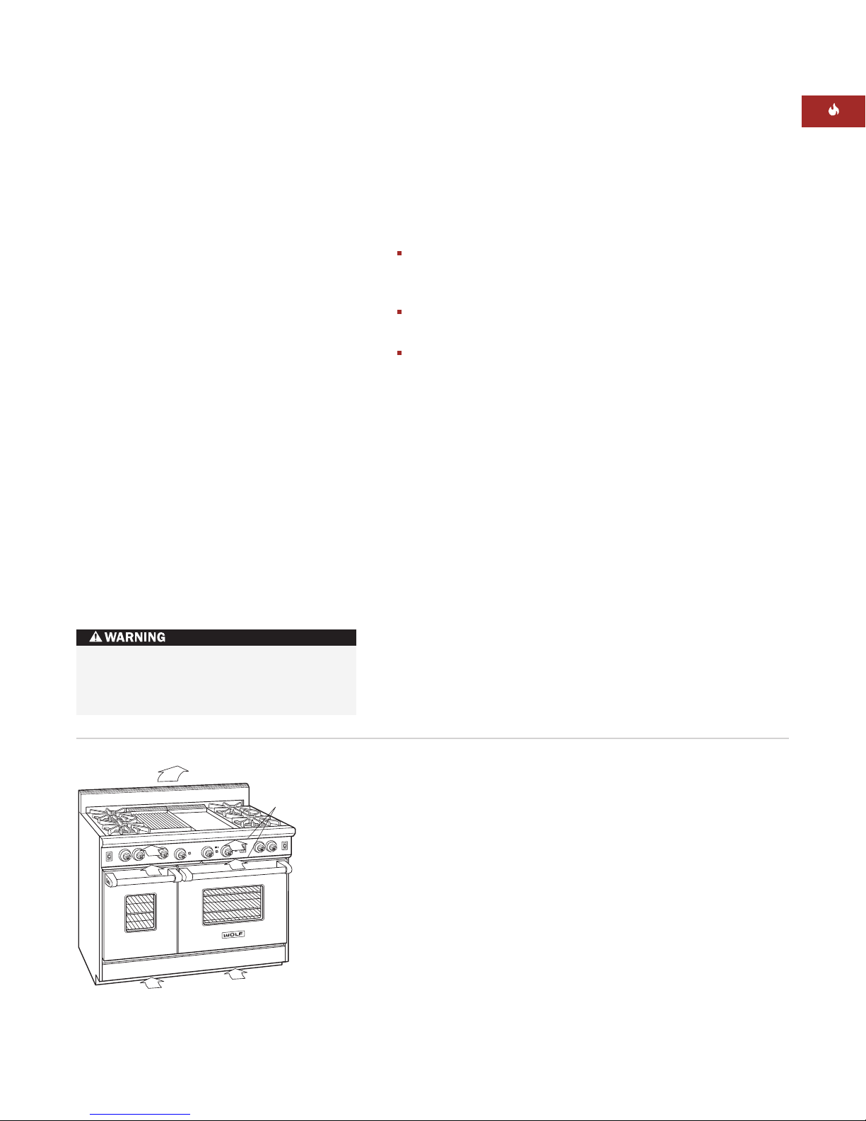
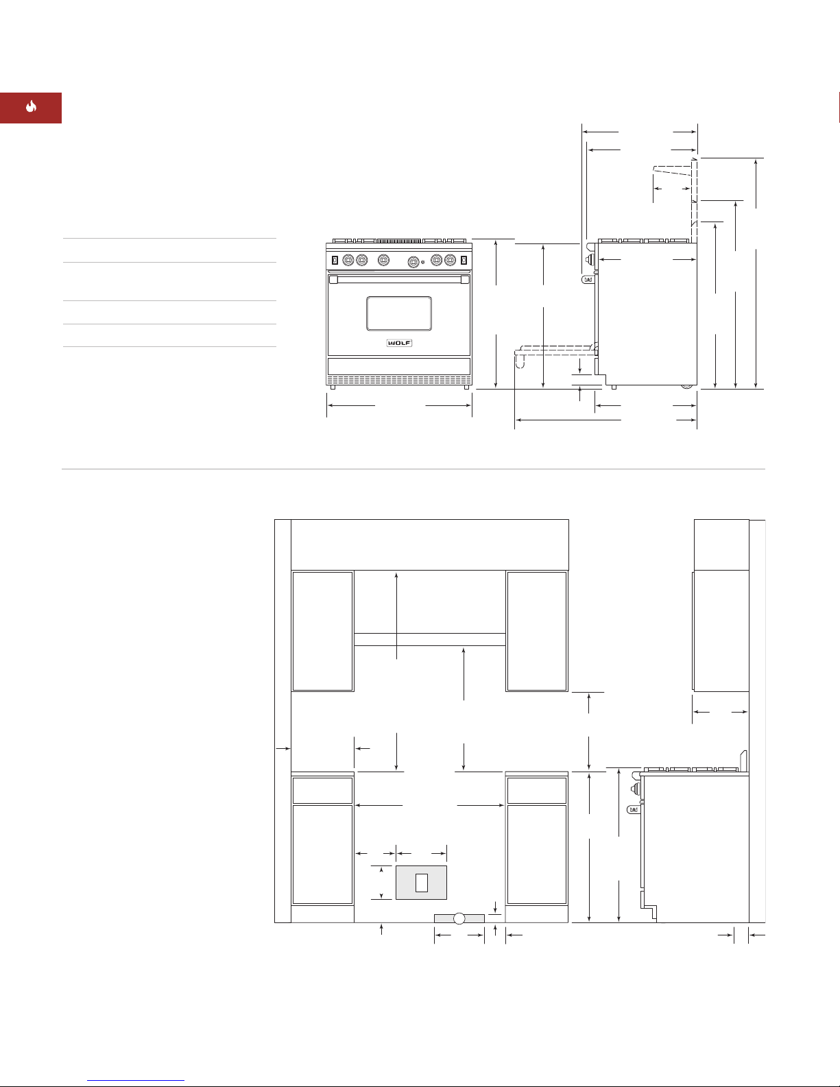
Record the model and serial numbers before
installing the gas range. Both numbers are
listed on the rating plate, located under the
drip pan that supports the cooking grates, on
the left inside wall of the range. Refer to the
illustration below. The rating plate for Model
R482CF is located on the right inside wall.
WOLF GAS RANGES
IMPORTANT NOTE:
Installation and service must be
performed by a qualified installer,
service agency or the gas supplier.
Warranty service must be performed
by a Wolf authorized service center.
Do not storeor use gasoline or
other flammable vapors and liquids
in the vicinity of this or any other
appliance.
Aventilation hood is recommended
for use with the Wolf gas range.
WHAT TO DO IF YOU SMELL GAS:
Do not tryto light any appliance.
Do not touch any electrical switch.
Do not use any phone in your
building.
Immediately call your gas supplier
from a neighbor’s phone. Follow the
gas supplier’s instructions.
If you cannot reach your gas
supplier, call the fire department.
If the information in this book is
not followed exactly, a fire or
explosion may result, causing
property damage, personal injury
or death.
RATING PLATE
INFORMATION
Model Number
Serial Number
This range can tip. Injuryto
persons could result. Install the
anti-tip device packaged with this
range according to instructions
on page 11.
Rating plate location
Location of rating plate
on the inside wall

4
BEFORE YOU START
Proper installation is your responsibility.
Installations must be performed by a
qualified or licensed contractor, plumber or
gas fitter, qualified or licensed by the state,
province or region where this appliance is
being installed. You must also assure that
electrical installation is adequate and
conforms with all local codes and ordi-
nances.
Wolf gas ranges are manufactured for use
with
natural gas
or
LP gas
.Please check
the product rating plate for type of gas
needed.
Proper gas connection must be available;
refer to Gas Supply Requirements on pages
12–13. Electrical ground is required; see
Electrical Requirements on page 14.
Check the location where the range will be
installed. The location should be away from
strong draft areas, such as windows, doors
and strong heating vents or fans. Do not
obstruct the flow of air. The area in which
you are installing this appliance must have
an adequate supply of fresh air to ensure
proper combustion and ventilation.
Make sure you have everything necessary
for correct installation. It is the responsibil-
ity of the installer to comply with the speci-
fied installation clearances. Refer to the
Installation Specifications illustrations for
your model on pages 7–10.
COMMONWEALTH OF MASSACHUSETTS
Installations and repairs must be performed
by a qualified or licensed contractor,
plumber or gasfitter qualified or licensed by
the state, province, or region where this
appliance is being installed.
Only use gas shut-off valves approved for
use within the state, province, or region
where this appliance is being installed.
Aflexible gas connector, when used, must
not exceed 3' (.9 m).
WOLF GAS RANGES

5
Dimensions in parentheses are in
millimeters unless otherwise specified.
INSTALLATION INSTRUCTIONS
VENTILATION CONSIDERATIONS
The front of your Wolf gas range must be clear
of any obstruction. For proper operation and
servicing, a clear area of at least 36" (914) in
front of the range is recommended.
Your kitchen must provide an adequate supply
of fresh air to assure proper combustion and
ventilation.
For the gas range, fresh air intakes are located
below the bullnose and control knobs. For the
oven burner, there are fresh air intakes at the
bottom front of the kick panel. Never block the
fresh air intakes, as they provide air required
for proper operation. Refer to the illustration.
Most of the heated air and burner combustion
by-products from the oven(s) exit through the
back stainless steel riser. Gas ranges can be
used with the optional island trim or 5" (127),
10" (254), or 20" (508) risers available through
your Wolf dealer.
Due to the high volume of ventilation air
required, a source of outside replacement air is
recommended. This is particularly important
for tightly sealed and insulated homes. A
qualified HVAC contractor should be consulted.
ACCESSORIES
Optional acces-
sories are available
through your
Wolf dealer. To
obtain local dealer
information, visit
the Locator section
of our website,
wolfappliance.com.
Keep combustibles such as solvents,
cleaning fluids, mops and rags, away from
the area surrounding all gas appliances.
Air
Intake
Air Intake
Heated Air Exits
Ventilation requirements
VENTILATION OPTIONS
IMPORTANT NOTE:
It is recommended that
you operate the Wolf gas range with a Pro
ventilation hood. Contact your Wolf dealer for
details.
Pro Wall Hood –
22" (559), 24" (610) or 27"
(686) depths and 30" (762) to 66" (1676)
widths in classic stainless steel.
Pro Island Hood –
36" (914) to 66" (1676)
widths in classic stainless steel.
Pro Hood Liner –
available in widths to
accommodate 30" (762) to 60" (1524) hood
shells.
All Pro ventilation hoods have welded seams,
sealed halogen lighting and removable, dish-
washer-safe stainless steel filters.
Blower requirements may vary due to length
of duct work and number of angles. The basic
recommendation is 1 CFM per 100 Btu/hr.
Always consult your HVAC professional for
more concise blower requirements.
IMPORTANT NOTE:
When installing a ventila-
tion hood, refer to the specific requirements
of the hood for the minimum dimension to
countertop.

ISLAND | PENINSULA INSTALLATIONS
Minimum clearances to combustible
surfaces:
For island installations,
the range should
not be installed within an enclosure having an
adjacent rear wall less than 12" (305) from
the rear of the unit that rises above the
countertop.
For peninsula installations,
the range must
have a 6" (152) minimum clearance to the side
wall, left or right side, and 12" (305) minimum
clearance to the rear wall.
Refer to the Installation Specifications
illustrations for your model on pages 7–10 for
the exact rough opening dimensions.
6
WOLF GAS RANGES
INSTALLATION SPECIFICATIONS
MINIMUM CLEARANCES
IMPORTANT NOTE:
Caution must be used in
planning the proper installation of the Wolf gas
range to avoid fires or damage to adjacent
cabinetry or kitchen equipment. Be sure to
follow the minimum clearances established in
the finished rough opening dimensions.
Refer to the Installation Specifications
illustrations for your model on pages 7–10 for
the exact rough opening dimensions.
WALL INSTALLATIONS
Minimum clearances to combustible
surfaces:
Aminimum clearance of 18" (457) must be
maintained between the countertop and the
bottom of overhead side cabinets or other
combustible materials.
Gas range: 6" (152) minimum clearance
from side walls, 0" (0) from rear wall.
Gas range with hood: 0" (0) from side
cabinets, 18" (457) minimum clearance
above countertop, 0" (0) from rear wall.
0" (0) clearance for adjacent combustible
materials below the countertop, both sides
and rear. The maximum depth of adjacent
overhead side cabinets is 13" (330).
Minimum clearances for gas ranges without
a ventilation hood:
Minimum vertical distance between the
surface burners or griddle to combustible
materials above the gas range must be
30" (762).
Minimum vertical distance between the
charbroiler (some models) to combustible
materials above the gas range must be
36" (914).
For all 60" (1524) models, the minimum
vertical clearance between the gas range
and combustible materials above the range
is 44" (1118).
Failure to locate the range without the
proper clearances will result in a fire
hazard.

7
Dimensions in parentheses are in
millimeters unless otherwise specified.
INSTALLATION INSTRUCTIONS
30"min (762)
COUNTERTOP
TO COMBUSTIBLE
MATERIALS
30"(762) TO 36"(914)
COUNTERTOP
TO BOTTOM OF
VENTILATION HOOD
VENTILATION
HOOD
301/4"(768)
FINISHED ROUGH
OPENING WIDTH
ISLAND INSTALLATIONS: 12" (305) MINIMUM CLEARANCE FROM BACK
OF RANGE TOCOMBUSTIBLE REAR WALL ABOVE COUNTERTOP –
0" (0) TONON-COMBUSTIBLE MATERIALS
G
5"
(127)
2"
(51)
12"
(305)
E
12"
(305)
10"
(254)
51/2"
(140)
8"
(203)
LOCATION OF GAS SUPPLY EXTENDS
3" (76) ON FLOOR FROM BACK WALL
3"
(76)
36"
(914)
18"min (457)
TO COUNTERTOP
37"
(940) TO
COOKING
SURFACE
13" max
(330)
6"min (152)
TO
COMBUSTIBLE
MATERIALS
(BOTH SIDES)
30" (762)
OVERALL WIDTH
36"
(914)
37" (940)
OVERALL
HEIGHT TO
COOKING
SURFACE
21/2"
(64)
241/2"(622)
251/4"(641)
LEGS AND CASTERS ALLOW
1" (25) HEIGHT ADJUSTMENT
433/8"(1102)
463/4"
(1187)
WITH 10"
RISER
563/4"
(1441)
WITH 20"
RISER
271/4"(692)
91/4"
(235)
283/8"(721)
OVERALL DEPTH
413/4"
(1060)
WITH 5"
RISER
INSTALLATION SPECIFICATIONS
OVERALL DIMENSIONS
Overall Width 30" (762)
Overall Height
(to cooking surface) 37" (940)
Overall Depth 283/8"(721)
Opening Width 301/4"(768)
Unit dimensions may vary by ±1/8"(3).
30" (762) GAS RANGE
IMPORTANT NOTE:
Aminimum 5" (127)
riser is required
when installing a
30" (762) gas range
against a
combustible surface.

8
WOLF GAS RANGES
30"min (762)
COUNTERTOP
TO COMBUSTIBLE
MATERIALS
36"min (914)
FOR
CHARBROILER
30"(762) TO 36"(914)
COUNTERTOP
TO BOTTOM OF
VENTILATION HOOD
VENTILATION
HOOD
361/4"(921)
FINISHED ROUGH OPENING WIDTH
ISLAND INSTALLATIONS: 12" (305) MINIMUM CLEARANCE FROM BACK
OF RANGE TOCOMBUSTIBLE REAR WALL ABOVE COUNTERTOP –
0" (0) TONON-COMBUSTIBLE MATERIALS
G
5"
(127)
2"
(51)
12"
(305)
E
12"
(305)
10"
(254)
51/2"
(140)
8"
(203)
LOCATION OF GAS SUPPLY EXTENDS
3" (76) ON FLOOR FROM BACK WALL
3"
(76)
36"
(914)
18"min (457)
TO COUNTERTOP
37"
(940) TO
COOKING
SURFACE
13" max
(330)
6"min (152)
TO
COMBUSTIBLE
MATERIALS
(BOTH SIDES)
36" (914)
OVERALL WIDTH
36"
(914)
37" (940)
OVERALL
HEIGHT TO
COOKING
SURFACE
21/2"
(64)
241/2"(622)
251/4"(641)
LEGS AND CASTERS ALLOW
1" (25) HEIGHT ADJUSTMENT
433/8"(1102)
463/4"
(1187)
WITH 10"
RISER
563/4"
(1441)
WITH 20"
RISER
271/4"(692)
91/4"
(235)
283/8"(721)
OVERALL DEPTH
413/4"
(1060)
WITH 5"
RISER
INSTALLATION SPECIFICATIONS
OVERALL DIMENSIONS
Overall Width 36" (914)
Overall Height
(to cooking surface) 37" (940)
Overall Depth 283/8"(721)
Opening Width 361/4"(921)
Unit dimensions may vary by ±1/8"(3).
36" (914) GAS RANGES
IMPORTANT NOTE:
Aminimum 5" (127)
riser is required
when installing a gas
range against a
combustible surface.
Aminimum 10" (254)
riser is required
when installing a
gas range with a
charbroiler or
griddle against a
combustible surface.

9
Dimensions in parentheses are in
millimeters unless otherwise specified.
INSTALLATION INSTRUCTIONS
30"min (762)
COUNTERTOP
TO COMBUSTIBLE
MATERIALS
36"min (914)
FOR CHARBROILER
30"(762) TO 36"(914)
COUNTERTOP TO
BOTTOM OF
VENTILATION HOOD
VENTILATION HOOD
LOCATION OF GAS SUPPLY EXTENDS
3" (76) ON FLOOR FROM BACK WALL
481/4"(1226)
FINISHED ROUGH OPENING WIDTH
3"
(76)
ISLAND INSTALLATIONS: 12" (305) MINIMUM CLEARANCE FROM BACK
OF RANGE TOCOMBUSTIBLE REAR WALL ABOVE COUNTERTOP –
0" (0) TONON-COMBUSTIBLE MATERIALS
26"
(660)
G
5"
(127)
2"
(51)
12"
(305)
E
12"
(305)
51/2"
(140)
8"
(203)
36"
(914)
18"min (457)
TO COUNTERTOP
37"
(940) TO
COOKING
SURFACE
13" max
(330)
6"min (152)
TO
COMBUSTIBLE
MATERIALS
(BOTH SIDES)
48" (1219)
OVERALL WIDTH
36"
(914)
37" (940)
OVERALL
HEIGHT TO
COOKING
SURFACE
21/2"
(64)
241/2"(622)
251/4"(641)
LEGS AND CASTERS ALLOW
1" (25) HEIGHT ADJUSTMENT
433/8"(1102)
463/4"
(1187)
WITH 10"
RISER
563/4"
(1441)
WITH 20"
RISER
271/4"(692)
91/4"
(235)
283/8"(721)
OVERALL DEPTH
413/4"
(1060)
WITH 5"
RISER
INSTALLATION SPECIFICATIONS
OVERALL DIMENSIONS
Overall Width 48" (1219)
Overall Height
(to cooking surface) 37" (940)
Overall Depth 283/8"(721)
Opening Width 481/4"(1226)
Unit dimensions may vary by ±1/8"(3).
48" (1219) GAS RANGES
IMPORTANT NOTE:
Aminimum 5" (127)
riser is required
when installing a gas
range against a
combustible surface.
Aminimum 10" (254)
riser is required
when installing a
gas range with a
charbroiler or
griddle against a
combustible surface.

10
44"min (1118)
COUNTERTOP
TO COMBUSTIBLE
MATERIALS
30"(762) TO 36"(914)
COUNTERTOP
TO BOTTOM OF
VENTILATION HOOD
VENTILATION HOOD
601/4"(1530)
FINISHED ROUGH OPENING WIDTH
ISLAND INSTALLATIONS: 12" (305) MINIMUM CLEARANCE FROM BACK
OF RANGE TOCOMBUSTIBLE REAR WALL ABOVE COUNTERTOP –
0" (0) TONON-COMBUSTIBLE MATERIALS
G
5"
(127)
2"
(51)
12"
(305)
E
12"
(305)
10"
(254)
51/2"
(140)
8"
(203)
LOCATION OF GAS SUPPLY EXTENDS
3" (76) ON FLOOR FROM BACK WALL
3"
(76)
36"
(914)
18"min (457)
TO COUNTERTOP
37"
(940) TO
COOKING
SURFACE
13" max
(330)
6"min (152)
TO
COMBUSTIBLE
MATERIALS
(BOTH SIDES)
WOLF GAS RANGES
60" (1524)
OVERALL WIDTH
36"
(914)
37" (940)
OVERALL
HEIGHT TO
COOKING
SURFACE
21/2"
(64)
241/2"(622)
251/4"(641)
LEGS AND CASTERS ALLOW
1" (25) HEIGHT ADJUSTMENT
433/8"(1102)
463/4"
(1187)
WITH 10"
RISER
563/4"
(1441)
WITH 20"
RISER
271/4"(692)
91/4"
(235)
283/8"(721)
OVERALL DEPTH
413/4"
(1060)
WITH 5"
RISER
INSTALLATION SPECIFICATIONS
OVERALL DIMENSIONS
Overall Width 60" (1524)
Overall Height
(to cooking surface) 37" (940)
Overall Depth 283/8"(721)
Opening Width 601/4"(1530)
Unit dimensions may vary by ±1/8"(3).
60" (1524) GAS RANGES
IMPORTANT NOTE:
Aminimum 5" (127)
riser is required
when installing a gas
range against a
combustible surface.
Aminimum 10" (254)
riser is required
when installing a
gas range with a
charbroiler or
griddle against a
combustible surface.

11
Dimensions in parentheses are in
millimeters unless otherwise specified.
UNPACK THE RANGE
Remove and discard all packing materials,
including cardboard and tape on the outside of
the range and inside the oven cavity.
IMPORTANT NOTE:
Donot discard the anti-tip
bracket packed with the range.
ANTI-TIP BRACKET
The rear channel brace is preinstalled at the
factory.Mount the anti-tip bracket at 61/2"(165)
minimum from floor. If the range legs are
adjusted higher than the 3" (76) minimum, the
anti-tip bracket must be raised accordingly.
Push the range back until it is flush with the
wall to engage the anti-tip bracket. The
maximum gap between the anti-tip bracket
and the rear channel brace should not exceed
1/4"(6). Refer to the illustration below.
INSTALLATION INSTRUCTIONS
WALL
FLOOR
61/2"
(165mm)
MIN TO
FLOOR
SIDE PANEL
ANTI-TIP BRACKET
REAR CHANNEL
BRACE
Anti-tip bracket installation
This range can tip. Injury to persons
could result. Install the anti-tip bracket
packed with the range. Follow these
installation instructions.
MOVING THE RANGE
IMPORTANT NOTE:
Before moving the range,
protect any finished flooring with appropriate
materials to avoid damage to the floor.
Due to the weight, a dolly with soft wheels
should be used to move your Wolf gas range.
The weight must be supported uniformly
across the bottom.
Move the range by dolly close to its installa-
tion location. The range can be tipped back
and supported on the rear casters while the
dolly is carefully removed. Be sure to protect
the flooring underneath the casters.
Gas and electrical connections should be made
and the backsplash and/or riser installed
before the range is placed in its final position.
Do not lift the range by the oven door
handle(s). This will damage the oven door
and hinges.

OVEN DOOR REMOVAL
12
Place Hinge Pin on
Spring Hinge Side of Door
Place Hinge Pins on
Spring Hinge Side of Door
Spring hinge location for 30" (762)
and 36" (914) gas ranges
Spring hinge locations for 48" (1219)
and 60" (1524) gas ranges
Hinge
Retainer
Plate
Upper Mounting
Screw
Hinge
Pin
Kickplate
Oven door removal
IMPORTANT NOTE:
The oven door(s) should
not be removed unless it is necessary to fit the
range through a tight doorway. Door removal
should only be done by a qualified service
technician or installer. Door removal and rein-
stallation may cause damage to the porcelain
interior of the oven or door(s).
If removal of the oven door(s) is necessary, a
hinge pin, supplied with the range, will need to
be inserted in the appropriate hinge arm. For
each oven door, only one hinge arm is spring
loaded, requiring use of the hinge pin for
removal of the oven door. The hinge pin will
be found taped to the inside of the oven door.
For 30" (762) and 36" (914) gas ranges, the
hinge pin will be inserted through the hole in
the right hinge arm (facing the unit). On 48"
(1219) and 60" (1524) gas ranges, the spring
hinges arelocated on the outer edges of the
unit. On these units, the left oven door will
have the spring hinge on the left side and the
right oven door will have the spring hinge on
the right side. Refer to the illustrations below
for the location of the spring hinge(s) for your
specific model.
If removal of the oven door(s) is necessary,
follow these steps:
1)
Open the oven door to its fully opened
position and insert the supplied door hinge
pin through the hole in the appropriate
hinge arm. Refer to the illustration below.
2)
Remove both upper and lower hinge
retainer mounting screws. NOTE: The oven
gasket may have to be moved slightly to
access the bottom screws.
3)
After removing the mounting screws, move
the hinge retainer plate forward slightly.
NOTE: The hinge retainer plate will remain
on the door hinge assembly after the
mounting screws have been removed.
4)
Carefully close the oven door to about a
60° angle from horizontal and lift the door
away from the oven. NOTE: A slight racking
motion may be required for removal.
5)
For 48" (1219) and 60" (1524) gas ranges,
complete these steps for both oven doors.
Do not lift or carry the oven door by the
door handle.
Failure to insert the hinge pin in the
appropriate hinge arm will cause damage
to the range. Minor injuries may occur.
WOLF GAS RANGES

13
Dimensions in parentheses are in
millimeters unless otherwise specified.
INSTALLATION INSTRUCTIONS
LEVEL THE RANGE
IMPORTANT NOTE:
The top of the range
must be level. Use both the adjustable front
legs and the adjustable rear casters to level the
range.
The 3" (76) front legs are adjusted by rotating
the bottom hexagonal portion of the leg. The
rear casters can be adjusted by rotating the
25/16"(59) nut on the caster. The range legs
and casters allow for a 1" (25) upward height
adjustment. Using the supplied wrench, rotate
the nut clockwise to raise the unit or counter-
clockwise to lower the unit. Refer to the illus-
tration below.
REAR CASTER
ADJUSTMENT
NUT
HEIGHT ADJUSTMENT
WITH SUPPLIED WRENCH
Rear caster adjustment

14
GAS SUPPLY REQUIREMENTS
GAS SUPPLY CONNECTION
IMPORTANT NOTE:
The gas range must be
connected to a regulated gas supply.
Connect the range to the gas supply line. The
gas supply line must be of adequate size to
properly service all gas appliances. If local
codes permit, a certified, 3' (.9 m) long, 1/2"or
3/4"ID flexible metal appliance connector is
recommended for connecting this range to the
gas supply line. The pipe coming out the back
of the range has 1/2"female threads.
IMPORTANT NOTE:
The supply line must
be equipped with an approved external gas
shut-off valve located near the range in an
accessible location. Do not block access to the
shut-offvalve. Refer to the illustration below.
The Wolf gas range functions up to 6,000'
(1828 m) in altitude without any adjustment. If
installation is above 6,000' (1828 m), contact
your Wolf dealer.
EXPLOSION HAZARD—
Use a certified gas supply line and install
a gas shut-off valve.
Securely tighten all gas connections.
The maximum gas supply pressure to the
regulator should never exceed 14" (34.9
mb) WC (water column); .5 psi (3.5 kPa).
Failure to do so can result in explosion,
fire or death.
WOLF GAS RANGES
Gas Supply
LineTo Appliance
SHUT-OFF VALV E
Open Position
Shut-off valve
IMPORTANT
NOTE
This installation
must conform with
local codes and
ordinances. In the
absence of local
codes, installations
must conform with
the American
National Standard,
National Fuel Gas
Code.
Before connecting the gas supply, make
sure all valves are in a closed position. Do
not connect the gas supply to an appli-
ance that shows any sign of physical
damage.
TYPES OF GAS
There are two types of gas, natural and liquid
propane (LP). Conversions are required in
order for appliances designed for one gas to be
operated with the other gas. Such conversions
must be performed by a Wolf authorized service
center. Make sure your gas range is correctly
adjusted for the type of gas being used.
The product rating plate has information on
the type of gas that should be used. If this
information does not agree with the type of
gas available, check with the local gas supplier.
The rating plate is located under the drip pan
that supports the cooking grates, on the left
inside wall of the range. Refer to the illustra-
tion on page 3. The rating plate for Model
R482CF is located on the right inside wall.

15
Dimensions in parentheses are in
millimeters unless otherwise specified.
INSTALLATION INSTRUCTIONS
GAS LEAK TESTING
Use a brush and liquid detergent to test all gas
connections for leaks. Bubbles around connec-
tions will indicate a leak. If a leak appears, shut
off the gas valve and adjust connections. Then
check connections again. Clean all the deter-
gent solution from the range.
Never test for a gas leak with a match or
other flame.
GAS SUPPLY REQUIREMENTS
GAS MANIFOLD PRESSURE
For Natural Gas:
Standard orifices
are set for 5" (12.5 mb) WC (water column).
Anatural gas pressure regulator is
installed.
For Propane (LP) Gas:
Standard orifices
are set for 10" (25 mb) WC (water column).
Apropane gas pressure regulator is
installed.
Gas Supply Pressure:
For checking the
regulator setting, the maximum line
pressure for natural and propane (LP) gas:
14" (34.9 mb) WC; .5 psi (3.5 kPa). Minimum
line pressure for natural gas: 7" (17.5 mb)
WC. Minimum line pressurefor propane
(LP) gas: 11" (27.4 mb) WC.
Gas Supply Regulator:
To control and
maintain a uniformgas pressurein the gas
manifold, the unit must be used with a gas
pressure regulator. The burner orifices, etc.
aresized for the gas pressuredelivered by
the supplied regulator. Do not remove the
regulator.
The maximum gas supply pressureto
the regulator should never exceed 14"
(34.9 mb) WC; .5 psi (3.5 kPa).

16
WOLF GAS RANGES
ELECTRICAL SHOCK HAZARD –
Plug into a grounded 3-prong outlet.
Do not remove ground prong.
Do not use an adapter.
Failure to follow these instructions can
result in electric shock, fire or death.
The Wolf gas range requires a 110/120 V AC
electrical supply to operate the electronic
ignition system. The 6' (1.8 m) power supply
cord provided with the range is equipped with
a3-prong, grounded plug for protection
against shock hazard. The service should have
its own 15 amp circuit breaker.
IMPORTANT NOTE:
You must follow all
National Electrical Code and gas regulations.
In addition, be aware of local codes and ordi-
nances when installing your services.
IMPORTANT
NOTE
You must follow
all National
Electrical Code
regulations. In
addition, be aware
of local codes and
ordinances when
installing your
service.
RECOMMENDED GROUND METHOD
IMPORTANT NOTE:
This appliance must be
properly grounded to avoid shock hazard.
The range is equipped with a 3-prong ground
plug. To minimize possible shock hazard, the
cord must be plugged into a mating 3-prong
ground-type outlet, grounded to conform with
the National Electrical Code, ANSI/NFPA 70
latest edition, or Canadian Electrical Code
(CSA) and all local codes and ordinances.
Refer to the illustration below.
IMPORTANT NOTE:
You must have a properly
grounded, 3-prong outlet installed by a quali-
fied electrician. A ground fault circuit inter-
rupter (GFCI) is not recommended and may
cause interruption of operation.
IMPORTANT NOTE:
Do not ground to a gas
pipe.
WIRING DIAGRAM
The wiring diagram covering the control circuit
is located inside the lower panel, below the
oven door panels.
ELECTRICAL REQUIREMENTS
Grounding Plug
Grounding-Type
Electrical Outlet
Electrical ground

17
Dimensions in parentheses are in
millimeters unless otherwise specified.
INSTALLATION INSTRUCTIONS
Hinge
Retainer
Plate
Upper Mounting
Screw
Hinge
Pin
Kickplate
Oven door reinstallation
IMPORTANT NOTE:
Fully extend the hinge
claw which is opposite the hinge pin location
and insert into the hinge pocket prior to
inserting opposite side. This will ease the
installation of the oven door.
OVEN DOOR REINSTALLATION
IMPORTANT NOTE:
The oven door(s) should
not be removed unless it is necessary to fit the
range through a tight doorway. Door removal
should only be done by a qualified service
technician or installer. Door removal and rein-
stallation may cause damage to the porcelain
interior of the oven or door(s).
If the oven door(s) have been removed as
described on page 12, follow these steps to
reinstall:
1)
Hold the oven door on both sides and
position it with door hinges aligned with
openings in the oven frame.
2)
Holding the oven door at an approximate
30° angle from vertical, slide the hinges into
the openings until the bottom hinge arms
drop fully into the hinge receptacles.
3)
Open the oven door to its fully opened
position. Remove the hinge pin from the
appropriate hinge arm. Refer to the
illustration below.
4)
Reinstall the hinge retainer plate with upper
and lower mounting screws.
5)
Open and close the door completely to
ensure that it is properly installed.
6)
For 48" (1219) and 60" (1524) gas ranges,
complete these steps for both oven doors.
Donot lift or carry the oven door by the
door handle.

18
WOLF GAS RANGES
REMOVING THE RANGE
Ifremoving the gas range is necessary for
cleaning or service, shut off the gas supply.
Disconnect the gas supply and electrical
connections to the unit, then remove the
range. Reinstall in the reverse order and be
sure to check the gas connection for leaks.
Refer the Wolf Gas Ranges Use & Care
Information included with the range for
cleaning recommendations.
Be sure to disconnect the gas supply and
electrical connections before removing
the range.
VERIFY RANGE OPERATION
SURFACE BURNERS
IMPORTANT NOTE:
Prior to operating the
range, be sure to read the entire Wolf Gas
Ranges Use & Care Information included with
the range for important safety, service and
warranty information.
The surface burners use electronic igniters in
place of standing pilots. When the burner
control knob is pushed in and turned to the
HIGH position, the system creates a spark to
light the burner. This sparking continues until
the electronic ignition senses a flame.
Be sure to place the burner parts on each
burner base and install the burner grates
beforelighting.
To check operation of the surface burners,
push in and turn each control knob to the HIGH
position. The flame should light within four
seconds.
IMPORTANT NOTE:
Initial lighting of the
surface burners may take slightly longer, as air
in the system must be purged before gas can
be supplied to the burner.
If the burners do not light properly,turn
control knob to the OFF position. Check that
the burner parts are in the proper position.
Check that the power supply cord is plugged in
and that the circuit breaker or house fuse has
not blown. Check that the shut-off valve is in
the ON position. Check operation again,
waiting at least five minutes; if the burners do
not light properly at this point, contact a Wolf
authorized service center.
OVEN OPERATION
Turn the oven(s) on and verify that the oven(s)
are coming up to temperature.
IMPORTANT NOTE:
Asmall amount of
smoke and odor may be noticed during the
initial break-in period. Refer to the Gas
Ranges Use & Care Information for additional
information.

19
CONTACT
INFORMATION
Wolf Customer
Service:
800-332-9513
Website:
wolfappliance.com
INSTALLATION INSTRUCTIONS
The information and images are the copyright
property of Wolf Appliance Company, Inc., an
affiliate of Sub-Zero Freezer Company, Inc.
Neither this book nor any information or images
contained herein may be copied or used in whole
or in part without the express written permission
of Wolf Appliance Company, Inc., an affiliate of
Sub-ZeroFreezer Company,Inc.
©Wolf Appliance Company, Inc. all rights reserved.
IF YOU NEED SERVICE
If service is necessary, maintain the quality
built into your gas range by calling a Wolf
authorized service center.
Toobtain the name and number of a
Wolf authorized service center, check
the Locator section of our website,
wolfappliance.com
orcall Wolf Customer
Service at
800-332-9513
.
When calling for service, you will need the
model and serial numbers of the gas range.
Both numbers are listed on the product
rating plate, located under the drip pan that
supports the cooking grates, on the left
inside wall of the range. Refer to the
illustration on page 3. The rating plate for
Model R482CF is located on the right inside
wall.
TROUBLESHOOTING
IMPORTANT NOTE:
If the gas range does not
operate properly, follow these troubleshooting
steps:
Verify that power is being supplied to the
range.
Check the gas supply and electrical
connections to ensure that the installation
has been completed correctly.
Check that gas valves are turned to the ON
position.
Check polarity of the electrical outlet should
nuisance clicking of igniters occur immedi-
ately after installation.
If the range still does not work, contact a
Wolf authorized service center. Do not
attempt to repair the range yourself. Wolf
is not responsible for service required to
correct a faulty installation.

807582 REV-B 10/2006
WOLF APPLIANCE COMPANY, INC. P.O. BOX 44848 MADISON, WI 53744 800-332-9513 WOLFAPPLIANCE.COM
Other manuals for R304
7
This manual suits for next models
4
Table of contents
Other Wolf Range manuals

Wolf
Wolf DF30450/S/P/LP User manual

Wolf
Wolf CHALLENGER XL Series User manual

Wolf
Wolf DF364C User manual

Wolf
Wolf R304 Owner's manual

Wolf
Wolf 105 Owner's manual

Wolf
Wolf CHR User manual

Wolf
Wolf Range User manual

Wolf
Wolf DF30450/S/P/LP User manual

Wolf
Wolf 762 User manual

Wolf
Wolf CHALLENGER CHR-4-0 User manual

Wolf
Wolf C60CB-6FT24 User manual

Wolf
Wolf DF60650DGSP User manual

Wolf
Wolf F-37363 User manual

Wolf
Wolf 762 User manual

Wolf
Wolf Ranges Operating manual

Wolf
Wolf DF486C Instructions for use

Wolf
Wolf R484CG Instructions for use

Wolf
Wolf DF304 User manual

Wolf
Wolf R484CG User manual

Wolf
Wolf R606DGLP User manual