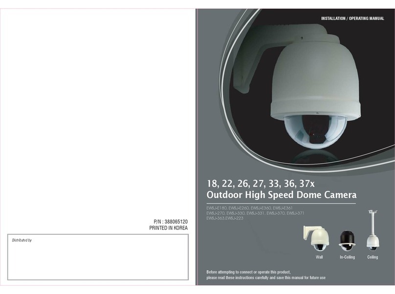
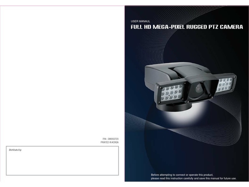
Wonwoo MMK-H208 Installation instructions

IR PTZ Camera
INSTALLATION / OPERATING MANUAL
- Before attempting to connect or operate this product,
please read these instructions carefully and save this manual for future use.
- The design and specifications are subject to be changed without prior notice to improve
product’s quality.

P/N : 388068605
TABLE OF CONTENTS
3p.
4p.
4p.
5p.
6p.
7p.
9p.
9p.
30p.
40p.
40p.
40p.
40p.
41p.
42p.
45p.
1. PRECAUTIONS
1. 1 Important Safety Instruction ...................................................................................
2. GETTING STARTED
2. 1 Unpacking ..............................................................................................................
2. 2 Part name ..............................................................................................................
2. 3 DIP Switch Setting .................................................................................................
2. 4 Cable Connection ...................................................................................................
3. INSTALLATION
3. 1 Installation .............................................................................................................
4. MAIN SETUP MENU
4. 1 Initialize .................................................................................................................
4. 2 Motion Setting .......................................................................................................
4. 3 Dome Setting ........................................................................................................
4. 4 Clear Setting .........................................................................................................
4. 5 Factory set ...........................................................................................................
4. 6 PTZ Reset .............................................................................................................
4. 7 Other Quick Opercating Guide ...............................................................................
5. SPECIFICATION
5. 1 Mechanism Specification .......................................................................................
6. DIMENSION
6. 1 DIMENSION ..........................................................................................................
7. CONFIGURATION
7. 1 Connecting to Keyboard with DVR .........................................................................
02

1. 1 Important Safety Instruction
•
Read these instructions.
•
Pay attention on all the warnings.
•
Follow all instructions.
•
Do not block any ventilation openings. Install in accordance with the manufacturer's instructions.
•
Do not dissemble or insert foreign objects.
•
Do not install near any heat sources such as radiation, beat registers, stoves, or other apparatus.
(Including amplifiers) that produce heat.
•
Do not aim the camera at the sun or any other strong light source.
•
Do not install the camera in intermittent lighting environments.
•
Only use attachments/accessories specified by the manufacturer.
•
Use only with the cart, stand, tripod, bracket, or table specified by the manufacturer, or sold with
the apparatus. When a cart is used, use caution when moving the cart/apparatus combination
to avoid injury from tip-over.
•
Refer all servicing to qualified service personnel. Servicing is required when the apparatus has been
damaged in any way, such as power-supply cord or plug is damaged, liquid has been spilled or
objects have fallen into the apparatus, the apparatus has been exposed to rain or moisture, does not
operate normally, or has been dropped.
•
Installation should be done only by qualified personnel and conform to all local codes.
•
Installation should be done in a place strong enough to hold it.
•
Use only installation methods and materials capable of supporting four times the maximum specified load.
•
It is designed for indoor use only and it must not be installed where exposed to rain and moisture
without additional outdoor housing and bracket.
•
To prevent damage from water leakage when installing a mount outdoors on a roof or wall,
apply sealant around the bolt holes between the mount and mounting surface.
•
These instructions are for use by qualified service personnel only. To reduce the risk of electric shock
do not perform any servicing other that contained in the operating instructions unless you are qualified
to do so.
•
Only use replacement parts recommended by manufacturer.
ad these instructions.
1. PRECAUTIONS
03
2. 1 Unpacking
The following parts are supplied with the outdoor speed PTZ dome system.
2. GETTING STARTED
<Figure 1. package Components>
2. 2 Part name
<Wall type>
Wall bracket
Plate rubber
<Ceiling type>
TAPE SEALCeiling bracketWall bracket Mount+Socket+Cable
Mount joint Manual Power adaptor(Option)
SCREW (M4*8 SUS)
Screw Screw
SCREW (SET ANCHOR 1/4")
Body Mount Wiper(Spare)
FRONT BACK
ID Setting
Upgrade Port
Micro SD Card
IP Reset
Commnucation
Setting
SIDE
Safety Loop
*DIP S/W setting refers page 5.
1
2
3
4
5
6
04

2. 3 DIP Switch Setting
Before start up the dome camera, set the protocol and camera address and termination
set with dip-switches and click-switches as shown in the below diagram.
1.Set the camera address (ID)
2. Protocol, Baudrate, Camera setting
3.Set the termination On/Off
Address switch
Open the top cover of the product to set camera address.
* ID setting is 1~255 available S1
(x1)
S3
(x10)
S4
(x100)
S1 : 1-digit number of address
S3 : 10-digit number of address
S4 : 100-digit number of address
Ex) S4 = 1
S3 = 2
S1 = 8
The ID number is 128.
The device which is connected at the end of the line must have the
cable communication terminated. Without proper termination,
there is potential for control signal errors.
The product have the cable communication terminated by setting
the appropriate dip switch.
9
ON : Terminated
OFF : Not terminated
1 2 3 4 5 6 7 8 9 10
ON
SW2
DIP
SW3
1 2
ON DIP
1 2 3
OFF OFF OFF
OFF OFF ON
OFF ON OFF
OFF ON ON
ON OFF OFF
ON OFF ON
ON ON OFF
ON ON ON
PELCO-D
PELCO-P
WTX
EZP
NC
NC
NC
NC
PROTOCOL 4 5 6
OFF OFF OFF
OFF OFF ON
OFF ON OFF
OFF ON ON
ON OFF OFF
ON OFF ON
ON ON OFF
ON ON ON
2400
4800
9600
19200
38400
57600
115200
NC
BAUDRATE
9
OFF
ON
OFF
ON
RS LOOP
8
OFF
ON
NTSC
PAL
NTSC/PAL
1
OFF
ON
IP OFF
IP ON
IP SELECT 2
OFF
ON
OFF
PROGRAM MODE
BOOTO
7
OFF
ON
RS-422
RS-485
RSMODE 10
OFF
ON
NC
NC
NC
05

2. 4 Cable connection
2. 4. 2 RS-485/RS-422 Connection
2. 4. 1 Power/Data communication cable connection
RS-422/485 connection
The PTZ can be remotely controlled by an external device or control system, such as a control
keyboard or DVR, using RS-485 half-duplex, RS-422 duplex or simplex serial communication signals.
Connect marked TRx+, TRx- to Tx+ and Tx- of the RS-485 control system.
If control system is RS-422, connect Tx+,Tx- of controller to Rx+ and Rx- of the PTZ Camera series.
And also connect the Tx+, Tx- to Rx+, Rx- of the control device respectively. Total length
of the cable for communication should not exceed 1.2Km.
2. 4. 3 HD-SDI Output connection
Connect the HD-SDI out (BNC) connector to the monitor or video input of DVR. Video cable and
RS-485/422 communication cable are not provided in this product's package.
Do not connect the AC24V power terminal to
the communication terminal.
- Power Terminal: 2PIN
- Com Terminal: 4PIN
Caution
SPK:LGR
MIC:PK
RY1-COM:WT
RY1-NO:GRY
RY2-COM:VI
RY2-NO:BL
GND:GR
AL1:YL
AL2:OR
AL3:RD
AL4:BR
GND:BK
MAIN CABLE
HD-SDI CABLE
06

3. Installtion
- The following steps of installation and connection work should be done by qualified service personnel or system installers
and should conform to all local codes.
- Be sure to switch the camera off before installation is completed.
- Do not install the camera near the air outlet of an air conditioner.
- Before installation, set the dome system with Dip switch on the back side of the mechanism part, and assemble the mechanism
and housing according to the below instruction
3. 1 Installtion
Attach the provided wall bracket rubber to a wall bracket
as shown in the below picture.
After connecting the cable, set the mount
in the proper position and fix the 2 screws
(M4*8)
CEILING PIPE
Install calbes into the bracket first.
WALL BRACKET WALL BRACKET WALL BRACKET RUBBER
INSERT
MOUNT ADAPTOR
PIPE SOCKET CEILING PIPE
After connecting the cable, set the mount in the proper position
and fix the 2 screws (M4*8)
Install the bracket to the wall using anchor bolt.
When install the ceiling bracket, screw the ceiling pipe
to the pipe socket as figure.
Install the bracket to
the ceiling using
anchor bolt.
FRONT
FRONT
<Wall Mount Type>
<Ceiling Mount Type>
1 2
1
2 3
3 4
07

Fix the Fixture screw tightly.
1. Connect the safety loop on the body and mount back side.
2. Connect MAIN cable and HD-SDI cable onto the main body as figure.
(Caution! Fix the main body tightly.)
3. Align the arrow mark in the body and mount.
4. Fix the body by turn it to clockwise.
FIXTURE SCREW
OPEN
CLOSE
(Turn the body to clockwise)
SAFTY LOOP
08

4. MAIN SETUP MENU
4. 1 Initialize
4. 2 Motion Setting
The preset function is that the camera memorizes positions of the pan/tilt and zoom.
This function is a representative function of the speed dome which can find memorized
preset positions just by selecting the preset No. A Maximum of 255 Preset positions are toured in order.
4. 2. 1 Preset
(1) Select the Preset number
P001 : Defined Preset number / 001 : Undefined Preset number
Move : Select : NEAR
When the device is powered on, you can check the address,
version, protocol and video setting values.
INITIALIZE
: 001
: X. XX
: 1080p30/NTSC
: PELCO-D
: 2400.N.1
: XX XXX..OK
VER: XX, XX
OK
OK
PTZ ID
VERSION
D-OUTPUT
PROTOCOL
BAUDRATE
CAMERA
▷ PAN INIT . . . .
▷ TILT INIT . . . .
▷NORMAL SETTING WAIT . .
MAIN MENU
< NEAR / RIGHT ▷MOTION >
MOTION
▶
DOME
CAMERA
CLEAR
PTZ RESET
FACTORY SET
EXIT
MOTION MENU
< NEAR / RIGHT ▷PRESET >
PRESET ▶
TOUR
GROUP
SCAN
PATTERN
ALARM
AREA
PRIVACY
HOME POS
BACK EXIT
PRESET MENU
PRESET SELECT : 001
<EXIT FOCUS NEAR>
P001
006
011
016
021
026
031
036
041
P003
008
013
018
023
028
033
038
043
P002
007
012
017
022
027
032
037
042
P005
010
015
020
025
030
035
040
045
P004
009
014
019
024
029
034
039
044
PRESET MENU
< NEAR / RIGHT PRESETNUM >
NUMBER : 001
TITLE :
: AUTO
: OFF
FOCUS
EXIT TIME
POSITION SET ▶
SAVE CLR BACK EXIT
09

(3) Select the focus mode for Preset
(4) Define the Preset position
① Select the Position menu
or
NEAR
② Move and set the position ③ Set & Back
NEAR
(2) Set the Preset TITLE
Move : Select : or or Delete : or
TELE
JOYSTICK
WIDE
JOYSTICK
It’s available to set the desired TITLE, displayed on the executing screen of Preset.
After the TITLE is set, push the NEAR button to exit.
On focus menu, there are 3 modes
: AUTO, MANUAL, ONESHT.
* Focus will be adjusted once after preset moving.
① Select the Focus menu
or
NEAR
② Move and set the Focus Menu
PRESET POSITION
PRESET TITLE EDIT ( 01 )
< DELETE WIDE
< STORE TELE
BACK NEAR >
MOVE JOYSTICK >
TITLE :
0 1 2 3 4 5 6 7 8 9 (
) A B C D E F G H I J K
L M N O P Q R S T U V W
X Y Z . / , + - = < >
<EXIT FOCUS NEAR >
POSITION : 000. 0 000. 0
PRESET MENU
< NEAR / RIGHT ▷TITLE >
NUMBER : 001
TITLE :
: AUTO
: OFF
FOCUS
EXIT TIME
POSITION SET ▶
SAVE CLR BACK EXIT
PRESET MENU
< NEAR / RIGHT ▷PRESET POSITION >
NUMBER : 001
: OFF
TITLE
EXIT TIME
:
: AUTOFOCUS
POSITION SET ▶
SAVE CLR BACK EXIT
PRESET MENU
< NEAR / RIGHT ▷PRESET FOCUS >
NUMBER : 001
: OFF
TITLE
EXIT TIME
:
: AUTOFOCUS
POSITION SET ▶
SAVE CLR BACK EXIT
10

(6) “Save” above setting Pattern data to the memory.
(7) “CLR” means above setting Pattern data will not be
saved and be cleared.
(8) “BACK” means it goes back to the previous
menu :Motion.
(9) “EXIT” means it goes out of MENU.
PRESET MENU
< NEAR / RIGHT ▷EXIT TIME >
NUMBER : 001
: OFF
TITLE
EXIT TIME
:
: AUTOFOCUS
POSITION SET ▶
SAVE CLR BACK EXIT
(5) EXIT TIME
Setting the dwell time to exit Preset mode after
completing Preset working.
(OFF / 5SEC / 10SEC / 20SEC / 30SEC / 1MIN /
5MIN / 10MIN / 30MIN) ※ Default : OFF
Select : or Set ON :
Set OFF :
NEAR
NEAR
PRESET MENU
< NEAR DATA SAVE >
NUMBER : 001
TITLE
EXIT TIME
:
: OFF
FOCUS
POSITION SET ▶
SAVE CLR BACK EXIT
11

(2) Set the Tour TITLE
Move : Select : or or Delete : or
TELE
JOYSTICK
WIDE
JOYSTICK
It’s available to set the desired TITLE, displayed on the executing screen of Tour.
After the TITLE is set, push the NEAR button to exit.
TOUR TITLE EDIT ( 01 )
< DELETE WIDE
< STORE TELE
BACK NEAR >
MOVE JOYSTICK >
TITLE :
0 1 2 3 4 5 6 7 8 9 (
) A B C D E F G H I J K
L M N O P Q R S T U V W
X Y Z . / , + - = < >
(1) Select the Tour number
T01 : Defined Tour number / 01 : Undefined Tour number
Move : Select : NEAR
The Tour function consists of several presets run by turn. It is also adjusts the moving speed
(1~63 step) and dwell time (1~99secs). Maximum of 8 Tour functions are toured in order.
4. 2. 2 Tour
( 1 Tour can be set for 15 presets. )
※
MAIN MENU
< NEAR / RIGHT ▷MOTION >
MOTION
▶
DOME
CAMERA
CLEAR
PTZ RESET
FACTORY SET
EXIT
MOTION MENU
< NEAR / RIGHT ▷TOUR >
PRESET
TOUR ▶
GROUP
SCAN
PATTERN
ALARM
AREA
PRIVACY
HOME POS
BACK EXIT
TOUR MENU
TOUR SELECT : 01
< SEL ▷NEAR / MOVE JOYSTICK >
01 02 03 04 05 06
07 08
TOUR MENU
< NEAR / RIGHT TITLE >
NUMBER : 01
TITLE :
TOUR SET
TIME DISPLAY : OFF
SAVE CLR BACK EXIT
TOUR MENU
< NEAR / RIGHT TOUR NUM >
NUMBER : 01
TITLE :
TOUR SET
TIME DISPLAY : OFF
SAVE CLR BACK EXIT
<<FIRST TITLE SELECT>>
12

(3) Define the Preset position
① Move to the set-up window
or
NEAR
② Move and set the position ③ Set & Back
NEAR
(5) “Save” above setting Pattern data to the memory.
(6) “CLR” means above setting Pattern data will not be
saved and be cleared.
(7) “BACK” means it goes back to the previous
menu :Motion.
(8) “EXIT” means it goes out of MENU.
TOUR EDIT (01)
NO PRESET SPEED DWELL
01 ◀01 63 01
02 ◁ 02 63 01
03 XX XX XX
04 XX XX XX
05 XX XX XX
06 XX XX XX
07 XX XX XX
08 XX XX XX
< SEL & NEAR PRESET & LEFT >
TOUR MENU
PRESET SELECT : 001
<EXIT FOCUS NEAR >
P001
006
011
016
021
026
031
036
041
P003
008
013
018
023
028
033
038
043
P002
007
012
017
022
027
032
037
042
P005
010
015
020
025
030
035
040
045
P004
009
014
019
024
029
034
039
044
< SEL & NEAR DELETE WIDE >
TOUR MENU
< NEAR DATA SAVE >
NUMBER : 01
TITLE :
TOUR SET
TIME DISPLAY : OFF
SAVE CLR BACK EXIT
TOUR MENU
< NEAR / RIGHT TOUR SET >
NUMBER : 01
TITLE :
TIME DISPLAY : OFF
TOUR SET ▶
SAVE CLR BACK EXIT
TOUR MENU
< NEAR / RIGHT TIME DISPLAY >
NUMBER : 01
TITLE :
TOUR SET
TIME DISPLAY : OFF
SAVE CLR BACK EXIT
(4) Time Display
Display the remain time of each Preset dwell time
during Tour operation.(OFF / ON) ※Default : OFF
Select : or Set ON :
Set OFF :
NEAR
NEAR
13

(2) Set the Group TITLE
Move : Select : or or Delete : or
TELE
JOYSTICK
WIDE
JOYSTICK
It’s available to set the desired TITLE, displayed on the executing screen of Group.
After the TITLE is set, push the NEAR button to exit.
(1) Select the Group number
G01 : Defined Group number / 01 : Undefined Group number
Set from 1to 6 groups.
Move : Select : NEAR
4. 2. 3 Group
GROUP : You can make Max. 6 groups and call the saved tour by turn.
MAIN MENU
< NEAR / RIGHT ▷MOTION >
MOTION
▶
DOME
CAMERA
CLEAR
PTZ RESET
FACTORY SET
EXIT
MOTION MENU
< NEAR / RIGHT ▷GROUP >
PRESET
TOUR
GROUP ▶
SCAN
PATTERN
ALARM
AREA
PRIVACY
HOME POS
BACK EXIT
GROUP MENU
< NEAR / RIGHT GROUP NUM >
NUMBER : 01
TITLE :
GROUP SET
SAVE CLR BACK EXIT
GROUP TITLE EDIT
< DELETE WIDE
< STORE TELE
BACK NEAR >
MOVE JOYSTICK >
TITLE :
0 1 2 3 4 5 6 7 8 9 (
) A B C D E F G H I J K
L M N O P Q R S T U V W
X Y Z . / , + - = < >
GROUP MENU
< NEAR / RIGHT TITLE >
NUMBER : 01
TITLE :
GROUP SET
SAVE CLR BACK EXIT
<<FIRST TITLE SELECT>>
GROUP SELECT : 01
GROUP MENU
< SEL ▷NEAR / MOVE JOYSTICK >
G01 02 03 04 05 06
14

(3) GROUP SET
① Move to the set-up window
or
NEAR
② Move and set the position ③ Set & Back
NEAR
(4) “Save” above setting Pattern data to the memory.
(5) “CLR” means above setting Pattern data will not be
saved and be cleared.
(6) “BACK” means it goes back to the previous
menu :Motion.
(7) “EXIT” means it goes out of MENU.
GROUP EDIT (01)
NO TOUR
01 <001>
02 002
03 XXX
04 XXX
05 XXX
06 XXX
< SEL & NEAR PRESET & LEFT >
< SEL & NEAR DELETE WIDE >
GROUP MENU
< NEAR DATA SAVE >
NUMBER : 01
TITLE :
GROUP SET
SAVE CLR BACK EXIT
GROUP MENU
< NEAR / RIGHT GROUP SET >
NUMBER : 01
TITLE :
GROUP SET ▶
SAVE CLR BACK EXIT
- GROUP EDIT : Set the tour from 1 to 6 of group.
15

(2) Set the Scan TITLE
Move : Select : or or Delete : or
TELE
JOYSTICK
WIDE
JOYSTICK
It’s available to set the desired TITLE, displayed on the executing screen of Scan.
After the TITLE is set, push NEAR button to go out.
SCAN TITLE EDIT ( 01 )
< DELETE WIDE
< STORE TELE
BACK NEAR >
MOVE JOYSTICK >
TITLE :
0 1 2 3 4 5 6 7 8 9 (
) A B C D E F G H I J K
L M N O P Q R S T U V W
X Y Z . / , + - = < >
SCAN MENU
< NEAR / RIGHT TITLE >
NUMBER : 01
TITLE :
START POS
END POS
MOTION TYPE : NONE
DIRECTION : NONE
SPEED : NONE
DWELL : NONE
SAVE CLR BACK EXIT
(1) Select the Scan number
S01 : Defined Scan number / 01 : Undefined Scan number
Move : Select : NEAR
The Scan function means that the camera keeps panning between two programmed pan positions.
It is also adjusts the moving speed(1~63 step). Maximum 8 Scan functions are toured in order.
4. 2. 4 Scan
MAIN MENU
< NEAR / RIGHT ▷MOTION >
MOTION
▶
DOME
CAMERA
CLEAR
PTZ RESET
FACTORY SET
EXIT
MOTION MENU
< NEAR / RIGHT ▷SCAN >
PRESET
TOUR
GROUP
SCAN ▶
PATTERN
ALARM
AREA
PRIVACY
HOME POS
BACK EXIT
SCAN MENU
SCAN SELECT : 01
< SEL NEAR / MOVE JOYSTICK >
01 02 03 04 05 06
07 08
SCAN MENU
< NEAR / RIGHT SCAN NUM >
NUMBER : 01
TITLE :
START POS
END POS
MOTION TYPE : NONE
DIRECTION : NONE
SPEED : NONE
DWELL : NONE
SAVE CLR BACK EXIT
NONE
16

(3) Set the Scan speed
Increase : or
Decrease : or
TELE
JOYSTICK
WIDE
JOYSTICK
It adjusts the moving speed from 1~63 steps.
(4) Set the Dwell Time
Increase : or
Decrease : or
TELE
JOYSTICK
WIDE
JOYSTICK
Dwell time means the time that the camera stay at
the start & end pan positions.
It’s adjustable from 00~59 seconds.
SCAN MENU
< NEAR / RIGHT MOVE SPEED>
NUMBER : 01
TITLE :
START POS
END POS
MOTION TYPE : NONE
DIRECTION : NONE
SPEED : NONE
DWELL : NONE
SAVE CLR BACK EXIT
SCAN MENU
< NEAR / RIGHT DWELL>
NUMBER : 01
TITLE :
START POS
END POS
MOTION TYPE : NONE
DIRECTION : NONE
SPEED : NONE
DWELL : NONE
SAVE CLR BACK EXIT
(5) Set the Motion Type
SCAN MENU
< NEAR / RIGHT MOTION TYPE>
NUMBER : 01
TITLE :
START POS
END POS
MOTION TYPE : NONE
DIRECTION : NONE
SPEED : NONE
DWELL : NONE
SAVE CLR BACK EXIT
Set PAN/TILT direction
When PAN is set,PAN SCAN is proceeded with the
specified coordinate value.
When TILT is set,TILT SCAN is proceeded with the
specified coordinate value.
Select : or Set ON :
Set OFF :
NEAR
NEAR
17

(8) Define the End position
① Select End Pos menu
or
NEAR
② Move and set the position ③ Go back
NEAR
SCAN END POSITIONSCAN MENU
< NEAR / RIGHT END POS >
NUMBER : 01
TITLE :
START POS ▶
END POS ▶
MOTION TYPE : NONE
DIRECTION : NONE
SPEED : NONE
DWELL : NONE
SAVE CLR BACK EXIT < EXIT FOCUS NEAR >
POSITION : 000. 0 000. 0
(7) Define the Start position
① Select Start Pos menu
or
NEAR
② Move and set the position ③ Go back
NEAR
(6) Set the Direction
SCAN MENU
< NEAR / RIGHT DIRECTION>
NUMBER : 01
TITLE :
START POS
END POS
MOTION TYPE : NONE
DIRECTION : NONE
SPEED : NONE
DWELL : NONE
SAVE CLR BACK EXIT
STRAT POSITION
SCAN MENU
< NEAR / RIGHT START POS >
NUMBER : 01
TITLE :
START POS ▶
END POS
MOTION TYPE : NONE
DIRECTION : NONE
SPEED : NONE
DWELL : NONE
SAVE CLR BACK EXIT
< EXIT FOCUS NEAR >
POSITION : 000. 0 000. 0
Select : or Set ON :
Set OFF :
NEAR
NEAR
Select Clock Wise or C_Clock Wise direction
When select C_Clock WISE, counterclockwise progression
When select Clock WISE, clockwise progression
PAN :
Set the UP & DOWN.
TILT :
- When Motion type is PAN, Pan is available.
- When Motion type is TILT, TILT is available.
18

(9) “Save” above setting Pattern data to the memory.
(10) “CLR” means above setting Pattern data will not be
saved and be cleared.
(11) “BACK” means it goes back to the previous
menu :Motion.
(12) “EXIT” means it goes out of MENU.
SCAN MENU
< NEAR DATA SAVE >
SAVE CLR BACK EXIT
NUMBER : 01
TITLE : NONE
START POS ▶
END POS ▶
MOTION TYPE : NONE
DIRECTION : NONE
SPEED : NONE
DWELL : NONE
19

(2) Set the Pattern TITLE
Move : Select : or or Delete : or
TELE
JOYSTICK
WIDE
JOYSTICK
It’s available to set the desired TITLE, displayed on the executing screen of Pattern.
After the TITLE set, push NEAR button to go out.
PATTERN MENU
< NEAR / RIGHT TITLE >
NUMBER : 01
TITLE :
RECORD
PLAY
SAVE CLR BACK EXIT
PATTERN TITLE EDIT ( 01 )
< DELETE WIDE
< STORE TELE
BACK NEAR >
MOVE JOYSTICK >
TITLE :
0 1 2 3 4 5 6 7 8 9 (
) A B C D E F G H I J K
L M N O P Q R S T U V W
X Y Z . / , + - = < >
(1) Select the Pattern number
PAT01 : Defined Pattern number / 01 : Undefined Pattern number
Move : Select : NEAR
The Pattern function memorizes User’s random moving path and zoom ratio. Total recording time
limit is 65secs and maximum 4 Pattern functions are toured in order.
4. 2. 5 Pattern
PATTERN MENU
< NEAR / RIGHT NUMBER >
NUMBER : 01
TITLE :
RECORD
PLAY
SAVE CLR BACK EXIT
MAIN MENU
< NEAR / RIGHT ▷MOTION >
MOTION
▶
DOME
CAMERA
CLEAR
PTZ RESET
FACTORY SET
EXIT
MOTION MENU
< NEAR / RIGHT ▷PATTERN >
PRESET
TOUR
GROUP
SCAN
PATTERN ▶
ALARM
AREA
PRIVACY
HOME POS
BACK EXIT
<<FIRST TITLE SELECT>>
PATTERN MENU
PATTERN SELECT:01
< SEL NEAR / MOVE & JOYSTICK >
< EXIT FOCUS NEAR >
01 02 03 04
20
Table of contents
Other Wonwoo Security Camera manuals

Wonwoo
Wonwoo WCA series Manual

Wonwoo
Wonwoo WCM-121N Installation instructions

Wonwoo
Wonwoo EB-363P User manual

Wonwoo
Wonwoo HDSC-S202M Installation instructions

Wonwoo
Wonwoo PS-100N Installation instructions

Wonwoo
Wonwoo PS-M032 Installation instructions

Wonwoo
Wonwoo wsj-300 User manual

Wonwoo
Wonwoo EWSJ-E180 Installation instructions

Wonwoo
Wonwoo ms 101 User manual

Wonwoo
Wonwoo WTK-M202 User manual