SM1111-04E Page 3 of 5 ©Aero-Motive Company Feb-03
CABLE STOP ADJUSTMENT
NOTE: Moving the cable stop will reduce the active travel distance. If additional cable extension is required,
extension cable assemblies are offered as an accessory.
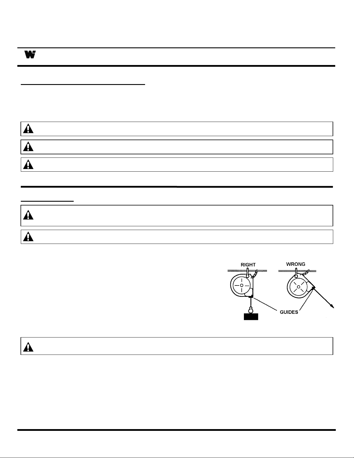
Cable stop can be moved up along the cable to attain the most desirable working height.
SERVICE
MAIN SPRING REPLACEMENT
CAUTION: Remove all tension before removing mainspring. Hazards or unsafe practices MAY result
in minor personal injury or product or property damage.
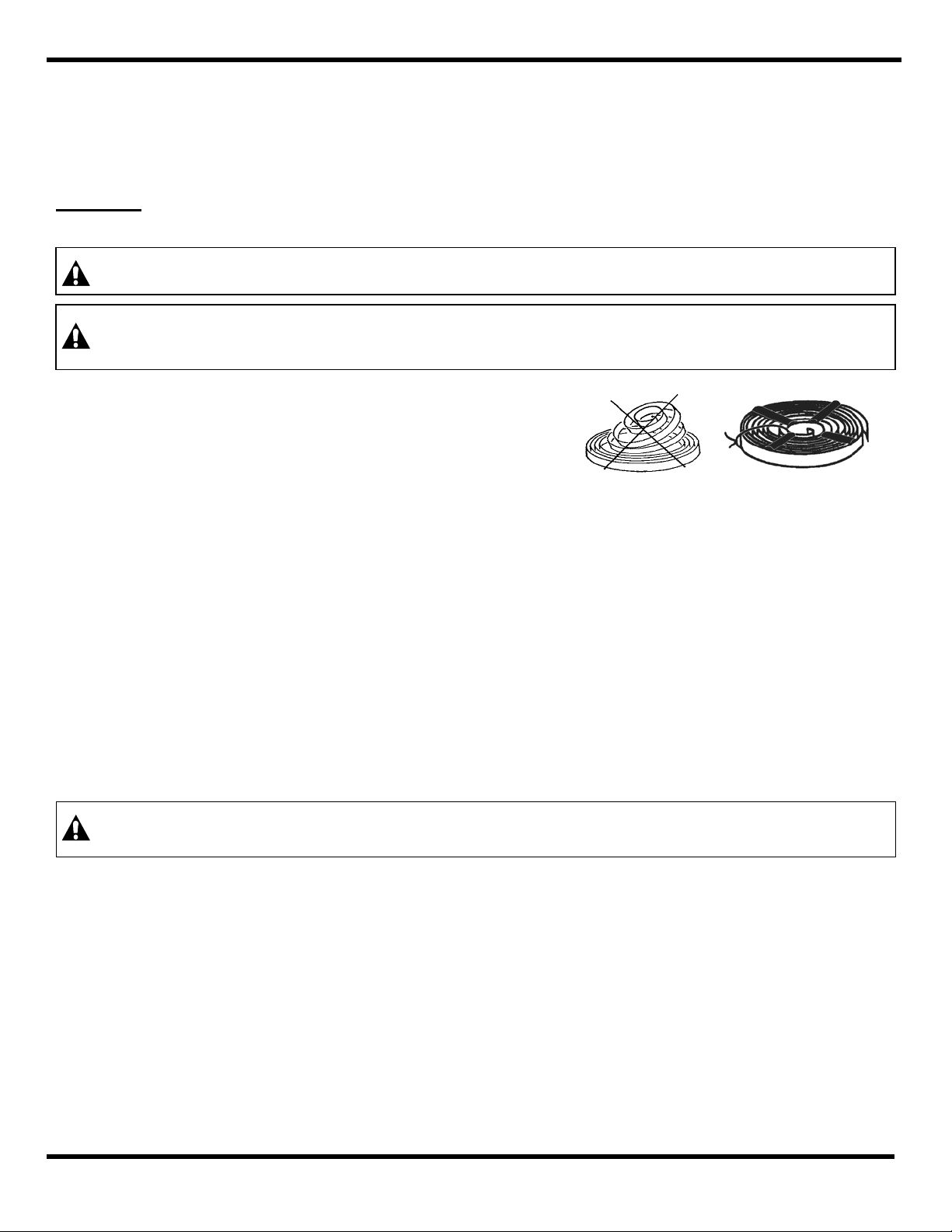
WARNING:
Spring is dangerous. Always wear gloves. Before removing broken spring, weld coils
together at four (4) locations or wrap securely with wire. Hazards or unsafe practices
COULD result in severe personal injury or death.
Remove All tension from main spring (See Spring
Tension Adjustment). Remove cotter pin and then clevis.
Next, remove the retaining ring and the three (3) screws,
also plates and screws. Remove housing. Remove
drum-cover nuts and cover. Carefully remove mainspring
from drum. Hub may come off shaft with spring.
If so, replace hub into new spring while making sure hub engages spring coils. Replace spring in
drum while making sure the spring hook engages with drum outer hook. To reassemble, reverse the
above procedure. Be sure the hub engages the pin on the main shaft when reassembling.
CABLE REPLACEMENT
Whenever a cable shows signs of deterioration, it should be replaced with a new cable. Remove All
tension from main spring (See Spring Tension Adjustment). Remove clevis by removing the cotter pin.
Next, remove the retaining ring and the three (3) screws, also plates and screws. Remove housing.
Remove nut and cable. Replace with new cable while threading it through guide first when reassembling.
RATCHET LOCK REPLACEMENT
Remove All tension from main spring (See Spring Tension Adjustment). Remove clevis by removing the
cotter pin. Next, remove the retaining ring and the three (3) screws, also plates and screws. Remove
retaining ring, washer, and spring lock, and retaining ring. The housing can now be removed. Remove
retaining ring and unclip spring, then remove ratchet lock. To reassemble, reverse the above procedure.
PARTS REPLACEMENT
CAUTION:
Always remove all spring tension (see “Spring Tension Adjustment”) before attempting to
disassemble internal parts. Always remove retractor reel from service. Hazards or unsafe
practices MAY result in minor personal injury or product or property damage.
NOTE: When ordering replacement parts, always include retractor reel model number and serial number.
All parts are replaceable in the field without special tools.
LUBRICATION
All bearings, springs, etc. are permanently lubricated at factory and should require no further lubrication.
MAINTENANCE & INSPECTION
Due to the design, this reel will require little maintenance other than a periodic check of the cable, safety
chain, and hanger for wear. All worn parts or cable should be removed from service and/or replaced at
once.