Woodland CALAHAN User manual

Metallschraube,
Vis en métal,
Vite di metallo
Metal bolt
M6 x 65 mm
D02
D01
D03
D04
D11
D10
D07
D06
D09
D05
D08
Kleiderstangenhalter
Porte tringle
Sostegni-asta appendiabiti
Hanging rail
Scharnierführung hier anschrauben
Visser les supports pour les
charničres ici
Avvitare qui il supporto-cerniera
Pre-drilled holes forhinges
Die Stabmuttern mit dem Schlitz nach außen in die
Bohrungen von Decke und Boden einsetzen.
Insérer les écrous, la fente vers l’extérieur, dans les trous du
dessous et du dessus de l’armoire.
I dadi con lo slot vengono inseriti nell elemento soffitto e
pianale, con il taglio all infuori, nei trafori previsti.
The slat-nut with the groove side should be appearing out of
holes in the upper and lower board.
Bauanleitung -
Fiche de montage -
Istruzione di montaggio - Assembly Instruction
CALAHAN - Art. 632
Metallschraube
Vis en métal
Vite
Metal bolt
M6 x 65 mm
R
Metallschraube,
Vis en métal,
Vite di metallo
Metal bolt
M6 x 65 mm
Metallschraube,
Vis en métal,
Vite di metallo
Metal bolt
M6 x 65 mm
Metallschraube, Vis en méta, Vite di metallo, Metal bolt - M6 x 65 mm
Stabmutter, Ecrou avec fente, Dado con lo slot, Slat nut - M6 x 13 mm
Fachbodenhalter, Support étagčres, Sostegno-mensola, Shelf holder
Spaxschraube, Vis cruciforme, Vite a croce da, Screw - 3,5 x 20 mm
Euro-Schraube, Vis Euro, Vite-Euro, EURO-screw - 6,3 x 11 mm
Spaxschraube, Vis cruciforme, Vite a croce da, Screw - 4,0 x 35 mm
Holzdübel, Tourillone en bois, Tassello di legno, Wooden peg - f 8 x 36 mm
M4-Schraube, Vis M4, Vite-M4, M4-screw - M4 x 30 mm
Irrtum und Druckfehler bleiben vorbehalten. Fautes et erreurs d’impression sous réserve. Not all specifications are guaranteed. © Copyrights by WOODLAND 2018
1. Die äußeren Türen sind fertig vorbereitet für
die Montage an den Schrank (s. Punkt 8. auf
Seite 3).
2. Wird der Schrank mit der Trennwand D05 auf
der rechten Seite montiert, wie es die Anleitung
zeigt, dann bekommt die mittlere Tür Ihren Griff
auf der linken Seite.
3. Soll die Trennwand D05 auf der linken Seite
montiert werden, müssen Boden und Decke
vertauscht und der Türgriff auf der rechten Seite
montiert werden.
4. Die Griffbohrungen für die mittlere Tür, je
nach Einbauposition links oder rechts
angeschlagen, von innen her mit einem 4mm
Bohrer durchbohren.
5. Den mitgelieferten Holzklotz dabei außen vor
die Bohreraustrittstelle drücken um ein
Ausreißen der Bohrung zu vermeiden.
6. Den C-Profilgriff mit zwei Schrauben M4 x 30
mm von der Innenseite der Tür her
anschrauben.
1. Le porte esterne sono già pronte per essere
montate (veda n. 8. pagina 3).
2. Nel caso di un montaggio con la parete
divisoria D05 sulla parte destra (come nel
disegno), la maniglia della porta centrale
dev´essere sulla sinistra.
3. Nel caso che la parete divisoria DO5 debba
essere montata sulla parte sinistra, devono
essere scambiati l´elemento soffitto con quello
pianale e la maniglia dev´essere sulla parte
destra.
4. A seconda della scelta della posizione (sx o
dx) delle maniglie della porta centrale, i trafori
previsti devono essere forati dall´interno con un
trapano con punta da 4mm.
5. Bloccare l´apertura del traforo per le maniglie
dal di fuori con il blocchetto di legno inviato, per
evitare di traforare completamente lo sportello.
6. Fissare le maniglie-C tramite le due viti da M 4
x 30 mm dall´interno della porta.
1.Les portes extérieures sont déjà prêtes pour
la fixation à l'armoire (voir étape 8, p.3)
2. Si la paroi de séparation D05 doit être fixée
sur le côté droit, comme indiqué sur le schéma,
la poignée de la porte du milieu doit être
installée à gauche.
3. Si la paroi de séparation D05 doit être fixée
sur le côté gauche, il faut alors échanger la
position du socle avec celle du plafond et fixer la
poignée à droite.
4. Percer à.p.d. l´intérieur de la porte du milieu
des trous prévus pour la poignée selon sa
position d´installation fixée soit à droite ou à
gauche, avec une perceuse munie d´un foret de
4mm.
5. Mettez la planchette de bois fournie comme
contre appui devant le point de sortie de la
perceuse pour éviter des déchirures durant le
forage.
6. Vissez la poignée profilée C à.p.d. l'intérieur
de la porte avec deux vis M4 x 30 mm
1. The outer doors are ready for installation on
the cabinet (see point 8 on page 4).
2. If the cabinet is mounted with the partition
D05 on the right side, as shown on the
instructions, then the middle door gets door
handle on the left side.
3. If the partition D05 is to be mounted on the left
side, the floor and ceiling must be reversed and
the door handle mounted on the right side.
4. Drill the holes for the middle door, hinged left
or right, depending on the installation position,
from the inside with a 4mm drill.
5. Press the wooden block supplied outside in
front of the drill exit point to prevent the bore
from tearing out.
6. Screw the C-profile handle with two M4 x 30
mm screws from the inside of the door.
Seite - Pagina - Page 2
D03
D05
D04
Spiegelbildlicher Aufbau, Mitteltür mit Griff rechts
Montage à l'envers, porte centrale avec poignet à gauche
Montaggio all inverso, Porta centrale con maniglia dx
D04
D05
Standardaufbau, Mitteltür mit Griff links
Montage standard, porte centrale avec
poignet à gauche
Montaggio-standard, Porta centrale con maniglia sx
D03
Holzklotz
Morceau de bois
Blocchetto di legno
4 mm Bohrer/Foret/Trapano
Befestigung der Türgriffe
Fixation des poignets de la porte
Montaggio delle maniglie
D04
D05
D03
D
F
I
GB
Irrtum und Druckfehler bleiben vorbehalten. Fautes et erreurs d’impression sous réserve. Not all specifications are guaranteed. © Copyrights by WOODLAND 2018

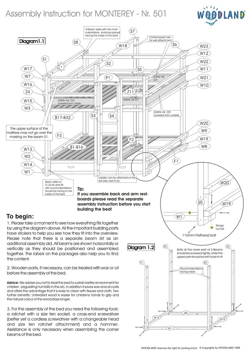
1. Stabmuttern in die dafür vorgesehenen Bohrungen in Decke D03, Boden D04 und Trennwand D05 einsetzen. Darauf achten, daß der Schlitz für den Schraubendreher nach außen zeigt. Die Bohrungen der
Stabmuttern zeigen immer nach oben.
2. In Seitenwände, Mittelwand, Trennwand sowie Decke, Boden und Sockel 8-mm-Holzdübel mit einem Hammer einschlagen.
3. Mittelwand D05 mit Decke D03 und Boden D04 mit Hilfe der Metallschrauben M6 x 65 mm verbinden.
4. Seitenwand D01 mit der Einheit D03 - D05 und Sockel D06 montieren. Metallschrauben M6 x 65 mm zunächst nur leicht anziehen.
5. Rückwände D09/D10/D11 einstecken. Die Rückwände bei dem Schrankteil mit der Trennwand werden nach der Schrankmontage von der Rückseite her mit der schmalen, weisslackierten Leiste und den
Spaxschrauben 3,5 x 20 mm befestigt.
Die Rückwände bei dem Schrankteil mit der Kleiderstange werden während der Schrankmontage mit Hilfe der Kunststoffleiste zusammengesteckt.
6. Seitenwand D02 anbringen und mittels Metallschrauben M6 x 65 mm festziehen.
7. Sämtliche Metallschrauben fest anziehen.
8. Topfscharniere ( Skizze 1.3 ) TYP-1 in die äusseren, TYP-2 in die mittlere Tür wie in ( Skizze 1.1 gezeigt einbauen und die Scharnierführungen an den Innenseiten der Seitenwände D01 und D02
montieren. Die Türen können mit den Verstellschrauben der Scharniere reguliert werden ( Skizze 1.2 ). In die Scharniere die "WOODLAND"-Abdeckblenden drücken.
Die “C”-Profilgriffe mit jeweils zwei Schrauben M4 x 30 mm von den Innenseiten der Türen her anschrauben ( Skizze 1.1 ).
9. Kleiderstange in die Halterungen einschieben. Die zwei Kleiderstangenhalter mit jeweils drei Euroschrauben 6,3x11 mm festschrauben.
10. Die Fachbodenhalter dort einstecken, wo später die Fachböden positioniert werden sollen. Fachböden auflegen.
Hinweis: Da unsere Möbel unbehandelt sind und demnach offenporig bleiben, können diese beim Transport Feuchtigkeit aufnehmen. Das spricht zwar für eine gesunde Wohnatmosphäre
(Feuchtigkeitsregulierung), aber es kann hierdurch dazu kommen, dass einzelne Möbelelemente, obwohl sie im Edelriftverfahren verleimt sind, geringe Toleranzveränderungen aufweisen und man bei der
Montage etwas geduldiger sein muss.
)
1.Insérer les écrous avec fente dans les trous respectifs des plafonds D03, D04 et D05 de l´armoire. Veillez à ce que la fente des écrous soit dirigée vers l'extérieur . Les trous des écrous avec fente doivent
toujours être positionnés vers le haut.
2. Enfoncer avec un marteau les chevilles de 8 mm dans les trous respectifs des Panneaux latéraux, centraux et des cloisons de séparations.
3. Relier à l´aide de la vis en métal M6 x 65 mm le panneau central D05 avec le plafond D03 et le fond D04 de l´armoire.
4. Relier le panneau latéral D01 avec l'ensemble D03, D05 et le socle D06. Visser légèrement les vis en métal M6 x 65 mm !
5. Insérer les panneaux arrières D09/D10/D11. Les panneaux arrières de la partie de l´armoire avec la cloison de séparation seront fixés par le dos après le montage de l´armoire, à l'aide de la barre étroite
laquée blanche et des vis de 3 x 20 mm. Les panneaux arrières de la partie de l´armoire avec la tringle sont raccordés durant l'installation de l´armoire à l'aide de la barre en plastique.
6. Monter le panneau latéral D02 et serrer à l'aide des vis à métal M6 x 65 mm.
7. Serrez toutes les vis métalliques.
8. Installer les charnières à boitier ( Skizze 1.3 ) TYP-1 à l'extérieur, TYP-2 à la porte centrale comme indiqué sur la Fig. ( Skizze 1.1 ), ainsi que les guides de charnière à l'intérieur des panneaux latéraux D01 et
D02. Les portes peuvent être ajustées à l'aide des vis de réglage des charnières ( Skizze 1.2 ). Enfoncer les caches charnières avec le logo "WOODLAND" pour couvrir ces dernières. Vissez les profils C à
l'aide de deux vis cruciformes de 4,2 x 35 mm à.p.d. l'intérieur des portes ( Skizze 1.1 ).
9.Introduire la tringle dans les supports. Serrer les deux supports des tringles à l'aide de trois vis cruciformes de 3x16 mm chacun.
10. Insérer les supports d'étagères là où les étagères doivent être placées plus tard. Accrocher les étagères.
Remarque: nos meubles étant non traités et donc à pores ouverts peuvent absorber l'humidité pendant le transport. Cela peut signifier certes une atmosphère de vie saine pour la chambre d´enfant vu ses
caractéristiques (Contrôle de l'humidité), mais il peut arriver que certains éléments des meubles, bien qu'ils aient une bonne finition, subissent de petits changements. Dans ces cas, nous vous conseillons de
poser des objets un peu lourd comme 2 à 5 livres sur ces parties pour 1 à 2 jours au couloir de la maison par ex. afin de regagner la forme initiale. Cependant, Il faudra se montrer un peu plus patient face à ces
cas qui arrivent d´ailleurs rarement.
Decke
Seitenwand
Die Schrauben nicht sofort fest
anziehen, sondern jeden Tag nur ein
paar Umdrehungen weiter eindrehen,
bis nach 2-3 Tagen die Seitenwand
an Decke bzw. Boden anliegt.
Fussboden
Das gewölbte Bauteil so auf eine flache Ebene legen.
4-5 schwerere Bücher über die Mitte
verteilt aufl gen. Nach 1 bis 2 Tagen ist
das Element ebener.
D
F
Planche latérale
Sol
Poser l’élément courbé sur une surface plane.
Ne pas serrer à fond les vis dès le
premier jour, mais d´une manière
progressive pendant 2 à 3 jours,
jusqu'à ce que la poutre latérale ait
atteint le socle ou la planche du haut.
Disposer 4-5 livres lourds au milieu. Au
bout d’1 ou 2 jours l’élément sera plus
droit .
Irrtum und Druckfehler bleiben vorbehalten. Fautes et erreurs d’impression sous réserve. Not all specifications are guaranteed. © Copyrights by WOODLAND 2018
Seite - Pagina - Page 3

1. I dadi con lo slot vengono inseriti nei trafori previsti dell´elemento soffitto D03 l`elemento pianale D04 e la parete divisoria DO5. Fare attenzione che il taglio del dado con lo slot sia all`esterno.
2. Inserire i tasselli di legno di 8mm con un martello di gomma, in modo cauto, nelle parti laterali, nella parete mediana, nella parete divisoria, nell`elemento soffitto, nell`elemento pianale e nello zoccolo.
3. Unire la parete mediana D05 con l`elemento soffitto D03 e l`elemento pianale D04 tramite le viti M6 x 65 mm.
4. Unire e montare l`elemento D01 con gli elementi D03 - D05 e lo zoccolo D06. Inizialmente non avvitare toppo forte le viti M6 x 65 mm.
5. Inserire le sottili tavole posteriori D09/D10/D11. Le sottili tavole posteriori della parte dell`armadio con la parete divisoria devono essere fissate dopo il montaggio dalla parte posteriore con il listello sottile
bianco e con le viti da 3 x 20 mm.
Le tavole sottili posteriori della parte dell`armadio con l`asta appendiabiti devono essere montate tramite il listello durante il montaggio .
6. Montare l`elemento D02 e fissarlo tramite le viti M6 x 65 mm.
7. Adesso avvitare in modo forte tutte le viti.
8. Montare i supporti-cerniera ( Schizzo 1.3 ) di tipo TYP-1 nelle porte esterne ed i supporti-cerniera di tipo TYP-2 nella porta mediana, come indicato nello ( Schizzo 1.1 ) e montare le guide-cerniera
dall`interno degli elementi laterali D01 e D02. Le porte possono essere regolate tramite le viti delle cerniere ( Schizzo 1.2 ). Inserire le coperture-"WOODLAND" nelle cerniere. Avvitare le maniglie “C”
dall`interno delle porte tramite le 2x viti da 4,2 x 35 mm ( Schizzo 1.1 ).
9. Inserire l`asta appendiabiti nei supporti e fissare le 2x aste appendiabiti con 3x viti-Euro 3 x 16 mm ciascuna.
10. Inserire i supporti delle mensole sull`altezza desiderata ed inserire le mensole.
Nota: Siccome i mobili di Woodland sono naturali/non trattati e sono molto traspiranti, possono assorbire dell`umidita durante il trasporto. Questo e' una caratteristica positiva, poiché consente di regolar
l´umidità nella camera. Potrebbe quindi capitare che singoli elementi mostrino leggere incurvature a causa dell`umidita. In questo caso, vi consigliamo di agire come mostrato e di avere piu' attenzione durante
il montaggio.
1. Insert slat nuts on the pre-drilled holes on the upper D03, lower D04 and middle D05 boards. Please note that the groove on the nut should be outside the hole. When assembling the upper and lower board,
sides with slat nuts should be facing up.
2. Plug in the wooden pegs on the side boards, middle board, dividing board as well as upper, lower and base boards with a hammer.
3. Assemble the middle board D05 with upper D03 and lower D04 boards with metal bolts M6 x 65 mm.
4. Lightly screw the side board D01 with the assembled unit D03 - D05 and base board D06 with metal bolt M6 x 65 mm.
5. Slide in the back board D09/D10/D11. Back board behind the dividing shelves should be fixed after the assembly of wardrobe using thin white band and 3 x 20 mm screw. The backboard behind the hanging-
rail should be attached toghether during the assembly of the wardrobe with the white band.
6. Attach the side board D02 with metal bolts M6 x 65 mm.
7. Tightly screw all the metal bolts.
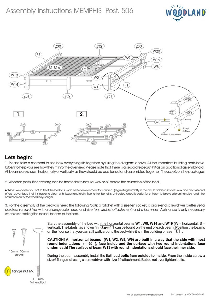
8. Fix the hinges ( Skizze 1.3 ) TYP-1 on the outer and, TYP-2 on the middle door as shown in ( Skizze 1.1 ) and attach the hinge-joint on the inner side of the side boards D01 and D02. The door can be adjusted
with adjusting-screw on the hinge ( Skizze 1.2 ). A hinge-cover with "WOODLAND" logo can be placed over the hinges. The handles of the door can be attached from the inside of the door using 4,2 x 35 mm
screw as shown on (Skizze 1.1 ).
9.Insert the hanging rail into its holders. Attach hanging-rail holders with screws 3x16 mm and place the hanging-rail. There are pre-drilled holes for the holders.
10. Plug in the shelf-holders in the pre-drilled holes and place the shelves on top.
Warning: Since our product is untreated and open-pored, it could be affected by the humidity during the transportation. The furniture is untreated to maintain good environment in a child's room.It could happen
that a piece of board is slightly bent but there is no need to worry! Just lay the board on the floor and place heavy books etc. for 1 to 2 days and it will return to its original shape.
Do not tighten the screws
immediately but tighten them little by
little for 2 to 3 days until the side
board becomes parallel to the top or
bottom board.
Place 4-5 heavy books in the middle of
the rounded area. After 1 to 2 days the
board will be flat again..
Place the arched board on the floor as shown above.
Floor
Side board
Upper board
GB
All`inizio non avvvitare troppo le viti,
bensi si avvitano le viti ogni giorno un
po di piu, affinche dopo 2-3 giorni la
parte laterale aderisce all elemento
soffitto anzi all`elemento pianale.
Posare 4-5 libri pesanti. Dopo 1-2 giorni l
elemento
Elemento soffitto
Parte laterale
Pavimento
Posare l elemento su una superficie piatta.
I
Irrtum und Druckfehler bleiben vorbehalten. Fautes et erreurs d’impression sous réserve. Not all specifications are guaranteed. © Copyrights by WOODLAND 2018
Seite - Pagina - Page 4

Spaxschraube
Vis cruciformes
Vite a croce
Screw
M4 x 25 mm
Scharnierschraube
Vis pour charnieres
Vite-cerniera
Screw for hinges
3,5 x 20 mm Skizze 1.1
Scharnierführung
Guides charničres
Guida-cerniera
Hinge-joint
Scharnier TYP 2 -Tür aufschlagend zueinander
Charniere TYP 2
Cerniera tipo TYP 2
Hinge TYP 2 -attached on the door
Seitenwand
Planche latérale
Parete laterale
Side board
Skizze 1.3
Mittelwand
Planche du milieu
Middle board
Parete mediana
Tür
Porte
Porta
Door
Scharnier TYP 1 - Tür aufschlagend voneinander
Charniere TYP 1
Cerniera tipo TYP 1
Hinge TYP 1 -attached on the door
Befestigungsschraube
Vis de fxation
Vite di fissaggio
Fixing screw
Schnellmontage CLIP
Montage rapide CLIP
CLIP montaggio rapido
Quick attachment CLIP
Höhenregulierung
Ajustement de la hauteur
Regolazione-altezza
Heigh adjustment
Spaltmaßregulierung
Régulation de l’écart des portes
Regolazione fessura-porta
Door opening adjustment
Führung
Guide
Guida-cerniera
Hinge-joint
Scharnier
Charniere
Cerniera
Hinge
Topf
Support
Supporto-cerniera
Hinge-attachment
Tiefenregulierung
Régulation
de profondeur
Regolazione profondita
Depth adjustment
Skizze 1.2
Tür
Porte
Porta
Door
Tür
Porte
Porta
Door
Irrtum und Druckfehler bleiben vorbehalten. Fautes et erreurs d’impression sous réserve. Not all specifications are guaranteed. © Copyrights by WOODLAND 2018
Seite - Pagina - Page 5
This manual suits for next models
1
Other Woodland Indoor Furnishing manuals

Woodland
Woodland MISSISSIPPI User manual

Woodland
Woodland CAPT'N COOK 503 User manual

Woodland
Woodland WINNIPEG 505 User manual

Woodland
Woodland Dakota 630 User manual

Woodland
Woodland MEMPHIS User manual

Woodland
Woodland SHORT/LONG ISLAND User manual

Woodland
Woodland MONTEREY 501 User manual

Woodland
Woodland CALGARY User manual

Woodland
Woodland AMARILLO 504 User manual