Woodland CAPT'N COOK 503 User manual

W1
W19
S5
W20
W23
W27
W13
W14
S4
S6
P1
S3
S5
S7
W26
W19
W28
W21
W22
W20
Z11
W9
W8
W2
W1
Z30
Z31
B1-B16
F1
F2
F3
Safety rail
Z27
tyilSafe ra Z25
Safety rail
Z24
Predrilled holes for
wall attachment
Not all specifications can be guaranteed. © Copyrights by WOODLAND 1998
110mm flathead bolt
Diagram1.1Diagram1.1
W14
S6
S5
W19
W8
W1
Indentations
face inside
Tighten the scews at the
bottom area and leave the
Diagram1.2Diagram1.2
2. Wooden parts, if necessary, can be treated with wax or oil
before the assembly of the bed.
Advice: We advise you not to treat the bed to sustain better environment for
the children (regulating humidity in the air). In addition it saves wax and oil
costs and offers the advantage that it is easy to clean with tissues and cloth.
Two further benefits: Untreated wood is easier for childrens hands to grip
and helps sustain the natural colour of the wood.
3. For the assembly of the bed you need the following tools:
a ratchet with a size ten socket, a cross-end screwdriver
(better yet a cordless screwdriver with a changeable head
and size ten ratchet attachment) and a hammer.
Assistance is only necessary when assembling the corner
posts of the bed.
1. Please take a moment to see how everything fits together
by using the diagram above. All the important building parts
have stickers to help you see how they fit into the overview.
Please note that there is a separate beam list as an
additional assembly aid. All beams are shown horizontally or
vertically as they should be positioned and assembled
together. The labels on the packages also help you to find
the content.
Before you begin:
Assembly Instructions for CAPT´N COOK - 503
For beams
Z30,Z31,S5,S6
side with the round
indentations face the
middle of the bed.
S2
W16
W15
W24
W17
W6
W25
W18
Horizontal beams with most
round indentations should
face the inner side of the bed.
Caution:
If you are going to attach the arm
and back rest set with your
WOODLAND bed, please read the
instructions for the arm and back
rest set before you start with the
assembly.
R
flange
nut M6

Familiarise yourself with the
location of the beams and
their 20mm circular indentations:
The inner side of the beams are
displayed as this is where most
of the circular indentations are
located.
W13, W15, W16 (midde indentation is used when the ladder
is installed at the head or foot of the bed!)
W17: Indentation A is to attach a ships wheel.
(diagram: bed inner side)
W14, W19, W20, W21, W22: (diagram: bed inner side)
W23: Large indentation is to attach the bed to the wall
(diagram: bed inner side)
Z11: (diagram: bed inner side) .
A
W9, W28: Notch for the mattress beam face up!
W2, W24: Round indentations “L” for ladder assembly (most indentations will not be used.)
W25: Also here not all L indentations will be used for ladder assembly.
W26, W27: (diagram: inner side)
W1, W8: Beam side with 2 indentations face down and 3 indentations face the inner side!
W18: Support beam for climbing rope (middle indentation will be necessary when using
a conversion kit!)
L L L L
Linner side
inner side
inner side
inner side
Notch beam
for mattress support
inner side
Beam List CAPT´N COOK
Art.-No. 503
Guidance for assembly
All specifications are not guaranteed © Copyrights by WOODLAND 1998
The stickers on the components
(“W1”, “W2”...etc.) can be
found on the end of every
beam. “W” for horizontal,
“S” for vertical!
Horizontal beams are shown
horizontally and vertical beams
are shown vertically.
L
S5
S6
S7S2
S3
Z31
S4
Z30
Middle beams
Ladder beams Corner beams
Holes for ladder handles
When setting up vertical
beams, use the upper
drill-holes since the lower
ones are necessary only for
other assembly options.
Warning! The upper three
circular indentations ( ) of
the corner beams S6 and
S5 should face the
the top-center beam (W18)
during the set up.
Hole for
wall
attachment
bed inner side
Corner beams
W6: short beam is assembled
below W22 or W16
R

Screw 35mm
Slide the drawer board through notch
Diagram1.3Diagram1.3
Diagram1.4Diagram1.4
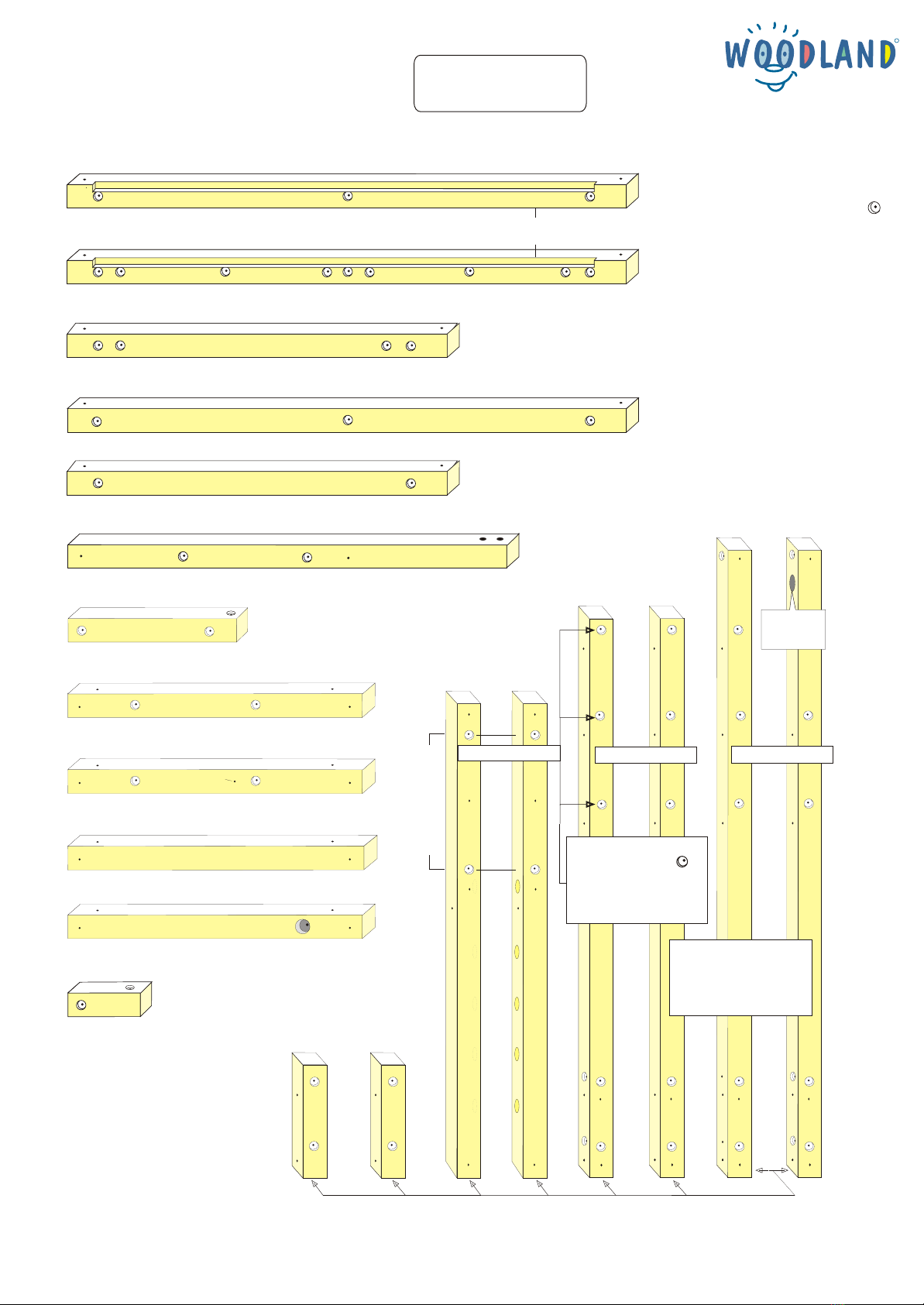
Start the assebly of the bed with the horizontal beams W1, W8, W14 and W19 (W = horizontal, S =
vertical). The labels of the beams, correspond to which is found on the end of the beams.
Position the beams on the floor in a way that you can still walk round the bed while it is in the building
phase. ( ).
Caution! All the following horizontal beams (W1, W2, W8, W9, W24, W25, W26, W27, W28) should
be positioned so that, the side with the most circular indentations face the inner side while
the surface with only two identations face underneath. The surface of the beams W13, W15, W16,
W17 and W23 with circular indentations must face inside.
To assemble these beams, the flathead bolts are hammered from the outside to inside. From the
inside secure it with size 6 flange nut using a screwdriver with size 10 attachment. But do not over
tighten bolts.
Diagram 1.1Diagram 1.1
Diagram1.2Diagram1.2
Page 2
How to set up the corner/middle beams S2, S5, S6, S7, Z30 und Z31: When assembling this type of bed please make sure
that the surface of the beam with the five circular indentations are facing the direction of the middle beam. Use bolt, washer and nut
to connect the vertical beams to horizontal beams . Continue with the
assembly of W25, W17, W26 and W23. The beams W17 and W23 can be
interchanged depending on where you want the bed to be attached to the wall.
The W23 beam has a hole for wall attachment.
Assemble the beams W2, W9, W24 and W28, which has notch to support the
mattress slats and these notch should face upward. Continue the assembly for
the beams W13 - W23 there will be an additional bolts for the end of vertical
beams, which are fixed from top to bottom at the end of the beam with M6 flange
nut. The horizontal beams on the upper bunk are built from top to bottom so that
it is easier to screw nuts with screwdriver. Then tightly screw the bolts at the
bottom so that it is easier to construct the rest of the bed.
Ladder assembly: in one end of five rung holes of beams S3 add drops of
wood glue (included in delivery). Tap in the steps using a hammer and wooden
board ( ). Do not put glue on the other side so that another step can be
added later to raise the height to 150 cm!
Diagram1.3Diagram1.3
Diagram 1.2Diagram 1.2
Before installing slats for mattress support assemble the
drawers together. Place drawer board in the notch
between the font and back board and attach the side
boards to front and back boards with screws ( ) . Fix
small wheels on a wooden block attached to the side
boards ( ). Both drawers should be placed from the
top through the space between the beams W1 and W2
from inside to outside . Corner boards F1, F2 and F3
should be attached to the beams S2/S7, S5/S6 und
Z30/Z31 with 40 x 40-mm-Brackets. So that the drawers
slide along the corner boards. The corner boards with
wider ends should be positioned in the back ( ).
Diagram1.4Diagram1.4
Diagram1.5Diagram1.5
Diagram 1.5Diagram 1.5
Leave this hole free
for other options
3 drops of glue in the
rungs holes
Beating wood to prevent
dent on the beam
S3
S4
Diagram1.5Diagram1.5
F2F3
Fix wheels to the wooden
blocks from below using
the screw 16 mm.
Z30
W1
S7
Install the drawer on the right side between the corner
board F1 and beams S5 and S6.
W8
Glue the rungs only on one side of the ladder (so
when the height of the bed is raised to 150 cm
another rung could be added to the ladder).
WARNING!
First attach the bracket on the board
F2 so that the drawers slide in
smoothly.
16mm 35mm
screws
110 mm
flathead bolt
flange nut M6
WOODLAND reserves the right for printing errors © Copyrights by WOODLAND 1998
R

W9 or W28
W2 or W24
Wooden peg 8 x 36 mm
Screw 35 mm
Diagram1.6Diagram1.6
Screw 35 mm
W9 or W28
W2 or W24
Diagram1.7Diagram1.7
S7S7
Anchor
Wood block
Wall attachment with
wooden block
S7S7
Anchor
Wall attachment without
wooden block
Diagram1.8Diagram1.8
The slatted frame: as shown in 15 wooden pegs
should be placed between each slats. The peg is attached to
one side of every slat except for the 16th slat. Slats are placed
on the notch of beams W2 and W9 and fixed with wooden
screws. The slatted frame should only be used with a mattress on top
for safety since there are space between the slats.
Other option: If you would like a bunk bed without a mattress, an extra slat
can be added (“Play Platform Set”, Order. No. 650). The wooden pegs
should be taken out and collected for later use. ( ).This applies
for the upper bunk of CAPT’N COOK.
Safety rails: assemble Z24 - Z27 with 35-mm-screws in the
centre between the mattress and middle guard rails (Z11,
W22, W27, W16). The front- (Z27) and back safety rails (Z24)
should be attached from inside and side safety rails Z24 and
Z25 attached from outisde.
Sailcloth: with a 50 cm long rope attached to the rope beam
W18 and on the side beam W17 or W23 respectively (only
included in the conversion kit 565).
Diagram1.6Diagram1.6
Diagram1.7Diagram1.7
Hang and fix the climbing rope with a 10mm thick Hanf rope and make a knot as you see on
the diagram on the top beam W18.
Steering wheel can be attached to the beam W17 (or to other 6-mm-holes) with a flathead
bolt and large washer (between beam and steering wheel ( ). The steering wheel is
than fixed with the accompanying M6-nut (can be recongnized by a green ring inside the nut).
Arch can be assembled over the ladder with 35mm-screws on the upper end of the ladder
beam S3 and S4 (use the pre-drilled holes in the arch).
Don’t forget to remove stickers on beam ends and other building parts
Diagram1.8Diagram1.8
Diagram 1.9Diagram 1.9
Wall attachment: Children play with the climbing rope and other
accessories with more power than adults could imagine, therefore for
sercurity it is better to attach the bed to a wall. It is recommended to use
the upper holes on the S7 beam for an attachment (also it is also
possible to attach the beam W23 to a wall) with the supplied anchor
and the 80mm or 100mm long Hexagonhead bolt. If the bed does not
have direct contact with the wall it is necessary to place a piece of wood
between the bed and the wall. After approx. three weeks retighten the
bolts. But make sure that the head of the bolt does not get buried in the
wood.
Important tip: WOODLAND safety rails are double the Euro-Norm EN
747.
If you have any technical questions to build the bed please contact us at
0049 2133 2482 - 19. The WOODLAND team hope that you and your
family will enjoy the WOODLAND advenuture beds!
Page 3
Diagram1.9Diagram1.9
washer approx.
30 mm in diameter
wheel
beam
W18 beam
Figure eight knot
for fixing a climbing rope
WOODLAND reserves the right for printing errors © Copyrights by WOODLAND 1998
R
Table of contents
Other Woodland Indoor Furnishing manuals

Woodland
Woodland CALGARY User manual

Woodland
Woodland MISSISSIPPI User manual

Woodland
Woodland MONTEREY 501 User manual

Woodland
Woodland CALAHAN User manual

Woodland
Woodland Dakota 630 User manual

Woodland
Woodland AMARILLO 504 User manual

Woodland
Woodland MEMPHIS User manual

Woodland
Woodland SHORT/LONG ISLAND User manual

Woodland
Woodland WINNIPEG 505 User manual
Popular Indoor Furnishing manuals by other brands

Songmics
Songmics RXJ10 instruction manual

Songmics
Songmics OBG064 manual

Workrite Ergonomics
Workrite Ergonomics Sentinel ST2E-54-72 Series Assembly/installation instructions

Safe
Safe SafeGate SC 701-50 user manual

chairholder
chairholder Chair 7 owner's manual

BePureHome
BePureHome Counter 801094-Z Mounting instructions