woodmizer Sawmill Guide

Wood-Mizer® Sawmill
Safety, Operation, Maintenance, &
Parts Manual
TD1 Transfer Deck rev. A1.00 - A4.00
Safety is our #1 concern! Read and understand
all safety information and instructions before oper-
ating, setting up or maintaining this machine.
June 2001
Form #1062

Table of Contents Section-Page
ii TD02doc072519 Table of Contents
SECTION 1 SAFETY 1-1
1.1 Safety Symbols.......................................................................................1-1
1.2 Safety Instructions..................................................................................1-2
SECTION 2 GENERAL INFORMATION 2-1
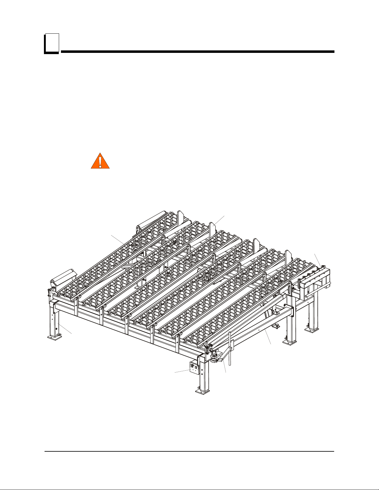
2.1 Transfer Deck Components....................................................................2-1
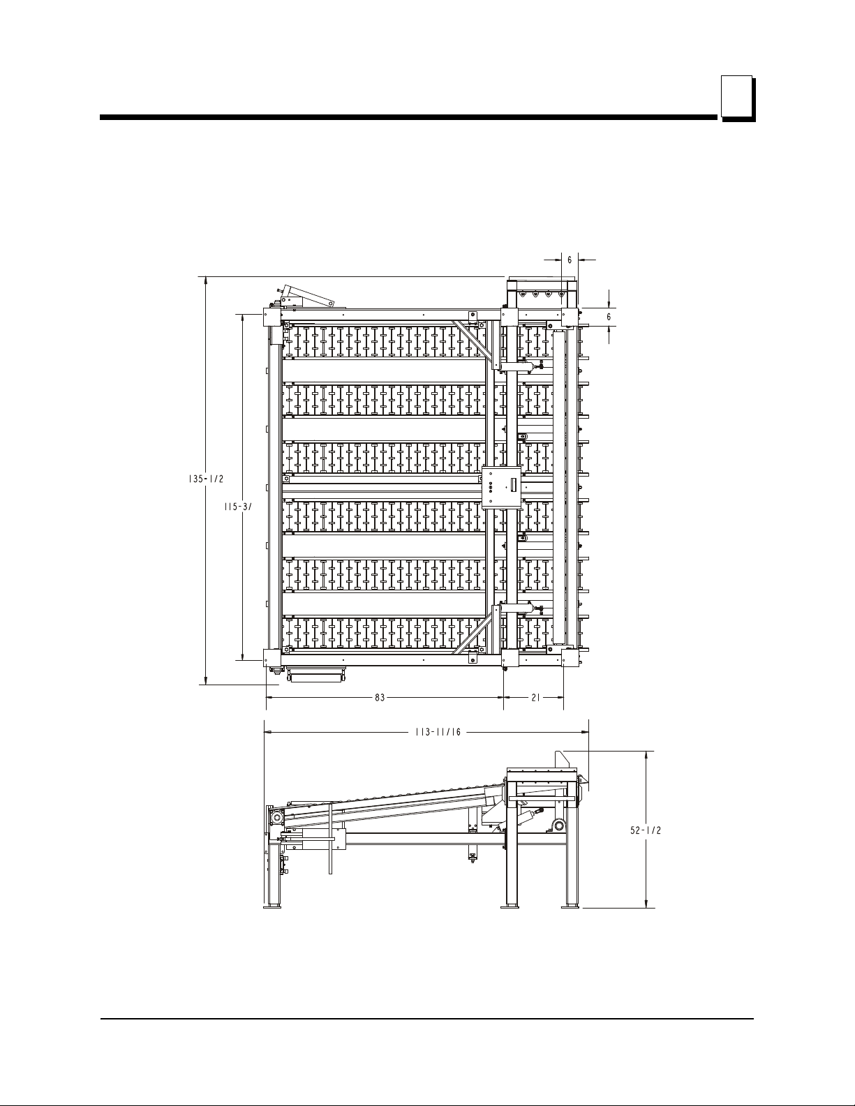
2.2 Overall Dimensions ................................................................................2-2
SECTION 3 INSTALLATION & SETUP 3-1
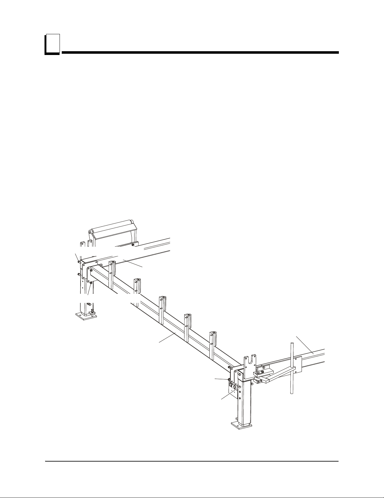
3.1 Installation ..............................................................................................3-1
3.2 Air Installation........................................................................................3-8
3.3 Setup .....................................................................................................3-10
3.4 Electrical Installation............................................................................3-12
3.5 Board Stop Adjustment ........................................................................3-15
SECTION 4 OPERATION 4-1
4.1 Control Box Operation ...........................................................................4-1
4.2 Swing Stop..............................................................................................4-3
SECTION 5 REPLACEMENT PARTS 5-1
5.1 Table Assembly......................................................................................5-1
5.2 Board Stop/Air Bag Assembly ...............................................................5-3
TD1 Rev. A4.00
5.3 Board Stop/Air Bag Assembly ...............................................................5-5
TD1 Rev. A1.00 - A3.01
5.4 Kicker & Air Cylinder............................................................................5-7
5.5 Lower Frame ..........................................................................................5-8
5.6 Swing Stop............................................................................................5-10
5.7 Control Box ..........................................................................................5-11
5.8 Photo Sensors .......................................................................................5-12
TD1 Retrofit
5.9 Photo Sensors .......................................................................................5-14
TD1 Rev. A1.00 - A4.00
SECTION 6 ELECTRICAL INFORMATION 6-1
6.1 Electrical Diagrams ................................................................................6-1
6.2 Electrical Component List......................................................................6-2
INDEX I
TOC

Safety
Safety Symbols
Safety TD02doc072519 1-1
1
SECTION 1 SAFETY
1.1 Safety Symbols
The following symbols and signal words call your attention to instructions concerning your
personal safety. Be sure to observe and follow these instructions.
DANGER! indicates an imminently hazardous situation
which, if not avoided, will result in death or serious injury.
WARNING! suggests a potentially hazardous situation
which, if not avoided, could result in death or serious injury.
CAUTION! refers to potentially hazardous situations which,
if not avoided, may result in minor or moderate injury or
damage to equipment.
IMPORTANT! indicates vital information.
NOTE: gives helpful information.
Warning stripes are placed on areas where a single decal
would be insufficient. To avoid serious injury, keep out of
the path of any equipment marked with warning stripes.

Safety
Safety Instructions
1
1-2 TD02doc072519 Safety
1.2 Safety Instructions
NOTE: ONLY safety instructions regarding personal injury are listed in this section. Cau-
tion statements regarding only equipment damage appear where applicable throughout
the manual.
WARNING! Clean sawdust from all guards, vents, con-
trol boxes, or any area where sawdust may gather after
every shift. Failure to do so may result in fire, causing
death or serious injury.
OBSERVE SAFETY INSTRUCTIONS
IMPORTANT! Read the entire Operator's Manual before operating
the transfer deck. Take notice of all safety warnings throughout this
manual and those posted on the machine. Keep this manual with
this machine at all times, regardless of ownership.
Also read any additional manufacturer’s manuals and observe any
applicable safety instructions including dangers, warnings, and
cautions.
Only persons who have read and understood the entire operator's
manual should operate the transfer deck. The transfer deck is not
intended for use by or around children.
IMPORTANT! It is always the owner's responsibility to comply with
all applicable federal, state and local laws, rules and regulations
regarding the ownership, operation of your Wood-Mizer products.
All Wood-Mizer product owners are encouraged to become thor-
oughly familiar with these applicable laws and comply with them
fully while using the machine.

Safety
Safety Instructions
Safety TD02doc072519 1-3
1
KEEP TRANSFER DECK AND AREA AROUND TRANSFER DECK CLEAN
DANGER! Maintain a clean and clear path for all necessary move-
ment around the machine and lumber stacking areas. Failure to do
so will result in serious injury.

Safety
Safety Instructions
1
1-4 TD02doc072519 Safety
CAUTIONS FOR TRANSFER DECK SETUP
WARNING! Securely fasten the feet of the transfer deck to the floor
before operating the machine. Failure to do so may result in seri-
ous injury or death.
CHECK TRANSFER DECK BEFORE OPERATION
DANGER! Make sure all guards and covers are in place and
secured before operating the transfer deck. Failure to do so may
result in serious injury.
KEEP PERSONS AWAY
WARNING! Keep all persons out of the path of moving
equipment and boards while operating transfer deck. Fail-
ure to do so may result in serious injury or death.

Safety
Safety Instructions
Safety TD02doc072519 1-5
1
USE PROPER PROCEDURE WHEN CONDUCTING MAINTENANCE
DANGER! Make sure all electrical installation, service and/or
maintenance work is performed by a qualified electrician and is in
accordance with applicable electrical codes.
DANGER! Hazardous voltage inside the control box and at the
motor can cause shock, burns, or death. Disconnect and lock out
power supply before servicing! Keep all electrical component cov-
ers closed and securely fastened during operation.
WARNING! Consider all electrical circuits energized and danger-
ous.
WARNING! Never assume or take the word of another person that
the power is off; check it out and lock it out.
WARNING! Do not wear rings, watches, or other jewelry while
working around an open electrical circuit.

General Information
Transfer Deck Components
2
2-1 TD02doc072519 General Information
SECTION 2 GENERAL INFORMATION
2.1 Transfer Deck Components
The Transfer Deck (TD1) enables you to change the direction of material flow. The trans-
fer deck is also equipped with the kicker system allowing you to separate boards and
cants. The following instructions will guide you in installation, operation, and alignment of
the Transfer Deck.
WARNING! Keep all persons out of the path of moving
equipment and boards while operating transfer deck. Fail-
ure to do so may result in serious injury or death.
See Figure 2-1. The main components of the Transfer Deck are shown below.
FIG. 2-1 TRANSFER DECK (TD1)
Transfer Deck Table
Kicker
Board Stop
Swing Stop Arm
Transfer Deck
Frame
Control Box
Adjustable
Base Leg
TD0022

General Information
Overall Dimensions
General Information TD02doc072519 2-2
2
2.2 Overall Dimensions
See Figure 2-2. The overall dimensions of the Transfer Deck (TD1) are shown below.
FIG. 2-2 TRANSFER DECK (TD1)
TD0028

Installation & Setup
Installation
3
3-1 TD02doc072519 Installation & Setup
SECTION 3 INSTALLATION & SETUP
3.1 Installation
This section describes the installation and setup procedures. Make sure the transfer deck
is properly assembled before operating the unit.
To assemble the transfer deck make sure to perform the following steps if necessary:
1. Position the transfer deck cross tube and the right and left transfer deck frames close to
each other. Use three 1/2-13 X 1 1/4 hex head bolts and 1/2-13 hex nylon lock nuts on
each side to install the transfer deck cross tube to the right and left frames. Tighten the
bolts and nuts.
See Figure 3-1.
FIG. 3-1
TD0029
Transfer Deck Left Frame
Transfer Deck Right Frame
Transfer Deck Cross Tube
½-13 Hex Nylon Lock Nut (3)
½-13 X 1 1/4 Hex Head Bolt (3)
½-13 Hex Nylon Lock Nut (3)
½-13 X 1 1/4 Hex Head Bolt (3)

Installation & Setup
Installation
Installation & Setup TD02doc072519 3-2
3
2. Rev. A4.00+: Position all the transfer deck frame parts as shown below. Use six 1/2-13 X
1 1/2" hex head bolts and 1/2-13 hex nylon lock nuts to install the transfer deck frame.
Tighten the bolts and nuts to secure the frame.
See Figure 3-2.
FIG. 3-2 REV. A4.00+
½-13 Hex
Nylon
Lock Nut (6)
½-13 x 1 ½” Hex Head Bolt (6)
½-13 Hex
Nylon Lock Nut (6)
½-13 x 1 ½” Hex Head Bolt (6)
TD0029-1

Installation & Setup
Installation
3
3-3 TD02doc072519 Installation & Setup
Rev. A1.00 - Rev. A3.01: Position all the transfer deck frame parts as shown below. Use
four 1/2-13 X 1 1/4" hex head bolts and 1/2-13 hex nylon lock nuts to install the transfer
deck frame. Tighten the bolts and nuts to secure the frame.
See Figure 3-3.
FIG. 3-3 REV. A1.00 - A3.01
TD0016
½-13 X 1 1/4 Hex Head Bolt (4)
½-13 Hex Nylon Lock Nut (4)

Installation & Setup
Installation
Installation & Setup TD02doc072519 3-4
3
3. Install the bottom of the kicker air cylinders to the transfer deck frame. Use 3/8-16 X 2 hex
head bolts and 3/8-24 nylon lock nuts to secure each cylinder in position. Make sure the
bolts and nuts are tightened.
See Figure 3-4.
FIG. 3-4
TD0018
3/8-16 X 2 Hex Head Bolt
3/8-24 Nylon Lock Nut

Installation & Setup
Installation
3
3-5 TD02doc072519 Installation & Setup
4. Install the lower table tube with bearings to the transfer deck frame. Use four 1/2-13 X 1
1/2 hex head bolts, 1/2 split lock washers, and 1/2 flat washers. Tighten the bolts to
secure the lower table cross tube in place.
See Figure 3-5.
FIG. 3-5
½ Split Lock Washer (4)
½ Flat Washer (4)
½ Flat Washer (4) ½-13 X 1 ½ Hex Head Bolt (4)
½-13 X 1 ½ Hex Head Bolt (4)
TD0030

Installation & Setup
Installation
Installation & Setup TD02doc072519 3-6
3
5. Install the center, right and left table tubes to the transfer deck table. Use two 5/8-11 X 1
3/4 hex head bolts and 3/8-16 X 1 nylon lock nuts on each tube. Make sure to secure the
tubes to the table.
See Figure 3-6.
FIG. 3-6
TD0020
3/8-16 X 1 Nylon Lock Nut
5/8 - 11 X 1 3/4 Hex Head Bolt
Right Table Tube
Center Table Tube
Left Table Tube
3/8-16 X 1 Nylon Lock Nut

Installation & Setup
Installation
3
3-7 TD02doc072519 Installation & Setup
6. Install each of six table rollers to the transfer deck table. Use four 3/8-16 X 3/4 hex head
bolts and 3/8-16 hex nylon lock nuts at the lower section of the transfer deck table.
Tighten the bolts and nuts. Use two 3/8-16 X 3/4 hex head bolts and 3/8-16 hex nylon lock
nuts. Secure the table roller at the upper section of the transfer deck table.
See Figure 3-7.
NOTE: Make sure all the bolts and nuts are tightened before operating the transfer deck
table.
7. Make the appropriate air hoses connections. See Section 3.2 Air Installation, for transfer
deck air system diagram.
FIG. 3-7
TD0021
3/8-16 X 3/4 Hex Head Bolt (4)
3/8-16 Hex Nylon
Lock Nut (4)
3/8-16 X 3/4 Hex Head Bolt (2)
3/8-16 Hex Nylon
Lock Nut (2)
Table Roller

Installation & Setup
Air Installation
Installation & Setup TD02doc072519 3-8
3
3.2 Air Installation
See Figure 3-8. The transfer deck air system diagram is shown below.
See Figure 3-9. The transfer deck air system diagram is shown below.
NOTE: Wood-Mizer highly recommends using the Transfer Deck together with the
FIG. 3-8
FIG. 3-9 TD1
Lift Valve
Air Cylinder
Air Cylinder
Air Bag
Air Filter
Air Regulator
Air Supply 70-90PSI
Filter to 40 Micron
TD0039-2
Kicker Valve
A
B
1
2
Lift Valve
Air Cylinder
Air Cylinder
Air Bag
Air Supply 70-90PSI
Filter to 40 Micron
TD0039-3B
Kicker Valve
A
B
1
2

Installation & Setup
Air Installation
3
3-9 TD02doc072519 Installation & Setup
Wood-Mizer Incline Conveyor. After connecting the transfer deck table to the air supply,
the transfer deck table automatically lowers when the board or cant gets between the
electronic sensors on the incline conveyor belt. The transfer deck table automatically
raises when the board or cant leaves the incline conveyor and there is no object on the
incline conveyor belt between the electronic sensors.
To operate the transfer deck with the incline conveyor, connect the air supply to the trans-
fer deck air supply line. NOTE: Make sure each hose fits tight on the fitting before operat-
ing the unit.

Installation & Setup
Setup
Installation & Setup TD02doc072519 3-10
3
3.3 Setup
Prepare a firm, level area where the transfer deck can be anchored before operating the
unit. A cement pad with 1/2” diameter anchor bolts is recommended.
WARNING! Securely fasten the feet of the transfer deck to
the floor before operating the unit. Failure to do so may
result in serious injury or death.
NOTE: If you use the Wood-Mizer Incline Conveyor, the distance between the transfer
deck and conveyor should be approximately 25” (635 mm).
See Figure 3-10.
The top of the conveyor drive roller should be approximately 2” (50mm) higher than the
top of the transfer deck rollers. Make sure that lumber can easily get to the transfer deck
table.
FIG. 3-10 TRANSFER DECK (TD1)
Approx.
25”
Approx.
2”
TD0023

Installation & Setup
Setup
3
3-11 TD02doc072519 Installation & Setup
Adjust the legs so each leg is in contact with the ground. Loosen the locking bolt. Turn the
adjustment bolt clockwise to raise, turn counterclockwise to lower the transfer deck
frame.
See Figure 3-11.
Secure the leg with the locking bolt. Tighten the jam nuts when the adjustment is com-
plete.
FIG. 3-11 TRANSFER DECK (TD1)
TD0005
Locking Bolt
Adjustment Bolt
Jam Nut
Table of contents
Other woodmizer Farm Equipment manuals