woodmizer BMS25 Guide

WARNING! Read and understand this
manual before using this machine.
!
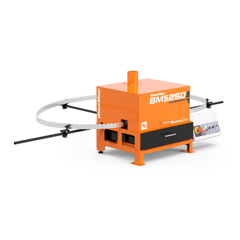
Blade Sharpener BMS25
Safety, Operation,
Maintenance, and Parts Manual
BMS25 rev. A1.00
Safety is our #1 concern!
Form #2448

Active Patents assigned to Wood-Mizer, LLC
Wood-Mizer, LLC has received patents that protect our inventions which are a result of a dedication to
research, innovation, development, and design. Learn more at: woodmizer.com/patents
©January 20, 2021 Wood-Mizer LLC
Printed in the United States of America, all rights reserved. No part of this manual may be reproduced in any form by any
photographic, electronic, mechanical or other means or used in any information storage and retrieval system without
written permission from
Wood-Mizer, LLC
8180 West 10th Street
Indianapolis, Indiana 46214
&DOLIRUQLD
3URSRVLWLRQ:DUQLQJ
:$51,1*%UHDWKLQJJDVGLHVHOHQJLQHH[KDXVWH[SRVHV\RXWRFKHPLFDOVNQRZQWR
WKH6WDWHRI&DOLIRUQLDWRFDXVHFDQFHUDQGELUWKGHIHFWVRURWKHUUHSURGXFWLYHKDUP
$OZD\VVWDUWDQGRSHUDWHWKHHQJLQHLQDZHOOYHQWLODWHGDUHD
,ILQDQHQFORVHGDUHDYHQWWKHH[KDXVWWRWKHRXWVLGH
'RQRWPRGLI\RUWDPSHUZLWKWKHH[KDXVWV\VWHP
'RQRWLGOHWKHHQJLQHH[FHSWDVQHFHVVDU\
)RUPRUHLQIRUPDWLRQJRWRZZZ3ZDUQLQJVFDJRY
:$51,1*'ULOOLQJVDZLQJVDQGLQJRUPDFKLQLQJZRRGSURGXFWVFDQH[SRVH\RXWR
ZRRGGXVWDVXEVWDQFHNQRZQWRWKH6WDWHRI&DOLIRUQLDWRFDXVHFDQFHU$YRLGLQKDOLQJ
ZRRGGXVWRUXVHDGXVWPDVNRURWKHUVDIHJXDUGVIRUSHUVRQDOSURWHFWLRQ
)RUPRUHLQIRUPDWLRQJRWRZZZ3:DUQLQJVFDJRYZRRG

Table of Contents Section-Page
Table of Contents BMS25 1/20/21 iii
SECTION 1 INTRODUCTION
1.1 About This Manual ................................................................................ 1-1
1.2 Getting Service....................................................................................... 1-1
1.3 Warranty................................................................................................. 1-2
1.4 Sharpener Components .......................................................................... 1-6
SECTION 2 SAFETY
2.1 Safety Symbols ...................................................................................... 2-1
2.2 Safety Instructions.................................................................................. 2-1
SECTION 3 ASSEMBLY
3.1 Stand Assembly...................................................................................... 3-2
3.2 Electrical Installation ............................................................................. 3-5
3.3 Blade Support Installation......................................................................3-7
3.4 Grinding Wheel Installation................................................................. 3-10
SECTION 4 SHARPENER ADJUSTMENTS
4.1 Hook Angle Adjustment ........................................................................ 4-1
4.2 Blade Rest Bolt Adjustment................................................................... 4-4
4.3 Grinding Wheel Shape........................................................................... 4-5
4.4 Face Grind Adjustment .......................................................................... 4-8
4.5 Tooth Height Adjustments ................................................................... 4-10
4.6 Gullet Grind Adjustment......................................................................4-11
4.7 Back Grind Adjustment ....................................................................... 4-13
4.8 Overview Of Adjustments .....................................................................4-1
SECTION 5 SHARPENER OPERATION
5.1 Operation................................................................................................ 5-1
5.2 Blade Installation ................................................................................... 5-3
5.3 Blade Removal....................................................................................... 5-5
SECTION 6 GENERAL INFORMATION
6.1 How To Use The Parts List.................................................................... 6-1
6.2 Stand Assembly...................................................................................... 6-2
6.3 Blade Support Assembly........................................................................ 6-4
6.4 Head Assembly ...................................................................................... 6-5
6.5 Panel Assembly...................................................................................... 6-7
6.6 Pusher Assembly.................................................................................... 6-8
6.7 Rocker Assembly ................................................................................... 6-9
6.8 Cam Assembly ..................................................................................... 6-10
SECTION 7 MAINTENANCE & TROUBLESHOOTING
7.1 Wiring Diagram ..................................................................................... 7-1
7.2 Sharpener Maintenance.......................................................................... 7-2

Introduction
About This Manual
Introduction WM doc 1/20/21 1-1
1
SECTION 1 INTRODUCTION
1.1 About This Manual
This manual replaces any previous information received on your Wood-Mizer®1equip-
ment.
The information and instructions in this manual do not amend or extend the limited war-
ranties for the equipment given at the time of purchase.
1.2 Getting Service
General Contact Information
Toll free phone numbers are listed below for the continental U.S. and Canada.
Office Hours: All times are Eastern Standard Time.
Please have your customer and serial number ready when you call.
Wood-Mizer will accept these methods of payment:
Visa, Mastercard, or Discover
COD
Prepayment
1.Wood-Mizer®is a registered trademark of Wood-Mizer LLC.
U.S. Patent No. 6,655,429.
United States Canada
Sales 1-800-553-0182 1-877-866-0667
Service 1-800-525-8100 1-877-866-0667
Website www.woodmizer.com www.woodmizer.ca
E-mail woodmizer@woodmizer.com oninfo@woodmizer.com
Monday - Friday Saturday
(Indianapolis Office Only)
Sunday
8 a.m. to 5 p.m. 8 a.m. to 12 p.m. Closed

Introduction
Warranty
1-2 WM doc 1/20/21 Introduction
1
Net 15 (with approved credit)
Shipping and handling charges based on size and quantity of order may apply. Items nor-
mally ship on the day they are ordered. Next Day or Second Day shipping is available at
additional cost.
If your sawmill was purchased outside the United States or Canada, contact your distribu-
tor for service.
1.3 Warranty
Wood-Mizer®LLC
Limited Product Warranty
Wood-Mizer LLC (“Warrantor”), an Indiana corporation with its principal place of business at 8180 West Tenth
Street, Indianapolis, IN 46214-2400 USA, warrants to the purchaser (“Purchaser”) that for the time periods
specifically stated herein and subject to the terms, conditions and limitations stated herein, the equipment
manufactured by the Warrantor will be free from defects in material and workmanship attributable to Warran-
USA and World Headquarters Canadian Headquarters
Serving North & South America, Oceania, East Asia
Wood-Mizer LLC
8180 West 10th Street
Indianapolis, IN 46214
Phone: 317.271.1542 or 800.553.0182
Customer Service: 800.525.8100
Fax: 317.273.1011
Email: infocenter@woodmizer.com
Serving Canada
Wood-Mizer Canada
396 County Road 36, Unit B
Lindsay, ON K9V 4R3
Phone: 705.878.5255 or 877.357.3373
Fax: 705.878.5355
Email: ContactCanada@woodmizer.com
Brazilian Headquarters European, African, and Asian Headquarters
Serving Brazil
Wood-Mizer do Brasil
Rua Dom Pedro 1, No: 205 Bairro: Sao Jose
Ivoti/RS CEP:93.900-000
Tel: +55 51 9894-6461/ +55 21 8030-3338/ +55
51 3563-4784
Email: info@woodmizer.com.br
Serving Europe, Africa, Western Asia
Wood-Mizer Industries Sp z o.o.
Nagorna 114
62-600 Kolo, Poland
Phone: +48.63.26.26.000
Fax: +48.63.27.22.327
Branches and Authorized Sales Centers
For a complete list of dealers, visit www.woodmizer.com

Introduction
Warranty
Introduction WM doc 1/20/21 1-3
1
tor so long as, during the warranty periods stated herein, the equipment is installed, operated and maintained
in accordance with the instructions provided by Warrantor.
EXCLUSIONS FROM 90 DAY, LIMITED ONE YEAR AND TWO YEAR WARRANTY
Warrantor shall have no responsibility under this warranty for any wear components, including, but not limited
to: belts, blade guides, blades, electric motor brushes, drum switches, filters, fuses, hoses, bearings (exclud-
ing cylindrical drive bearings), bushings, cable carriers, and spark plugs. All wear components are furnished
“as is”, without any warranty from Warrantor. This limited warranty does not cover any defects caused by
misuse, negligence, alterations, damage due to overload, abnormal conditions, excessive operation, acci-
dent, or lack of performance of normal maintenance services.
Several components which are used in the manufacture of the equipment but not manufactured by Warrantor,
such as cant hooks, power plants, laser sights, batteries, tires, and trailer axles have warranties provided by
the original equipment manufacturer (written copies available upon request). Warrantor does not separately
warrant such items. Components or equipment manufactured by third parties are not covered by this war-
ranty. Warrantor, however, will provide reasonable assistance to the Purchaser to make claims against any
PRODUCT MODEL CLASS LENGTH OF WARRANTY EFFECTIVE DATE
USA & CANADA NON USA
& CANADA
Portable Sawmills, Resaws,
Edgers LT, LX, HR, EG Two years One year
Date of purchase
Portable Sawmills with
Chassis
LT28, LT35, LT40, LT50,
LT70, LX450
Two years, excluding
the chassis, which
chassis shall have a
five year warranty
One year
Industrial Sawmills, Resaws,
Edgers
WM, HR, EG, TVS, SVS,
FS One year One year Date of purchase or
date of installation /
training (if applicable),
whichever occurs first,
not to exceed 6
months from date of
purchase
TITAN Industrial WB, TV, HR, EG, EA, MR One year One year
Material Handling TWC, IC, TD, LD, GC, CR,
CB, CC One year One year
Blade Maintenance Equipment BMS, BMT, BMST One year One year
Date of purchase
Options and Accessories Various One year1One year 1
1 Warranty on Options will match the warranty on the primary equipment when purchased on same invoice.
Moulders, Kilns MP, SD, KD One year One year
Extractor MD One year One year
Pallet Dismantler PD One year One year
Log Splitter FS One year One year
Replacement Parts Various 90 days 90 days

Introduction
Warranty
1-4 WM doc 1/20/21 Introduction
1
warranties applicable to such component parts as provided by such original equipment manufacturers. Com-
ponents or equipment manufactured by third parties are not covered by this Warranty.
FIVE YEAR LIMITED CHASSIS WARRANTY
The limited five year chassis warranty, described above, DOES NOT extend to (a) any damage stemming
from accident, improper towing, overload, abuse, misuse, abnormal conditions, negligence, excessive opera-
tion, or lack of maintenance, (b) rust caused by exposure to corrosive atmospheric conditions, or (c) the saw-
mill head, carriage, axle, brakes, or any hydraulic or electrical components attached to the chassis.
WARRANTOR’S OBLIGATIONS AS TO DEFECTS
In the event that the equipment fails to perform due to defective materials or workmanship attributable to War-
rantor under normal use and service within the established warranty period, Purchaser’s sole and exclusive
remedy and Warrantor’s sole liability shall be to replace or repair, in Warrantor’s sole and subjective discre-
tion, any defective part at Warrantor’s principal place of business without cost to the Purchaser if such defect
exists. The determination of whether a product is defective shall be made by Warrantor in Warrantor’s sole
and subjective discretion. The Purchaser must notify Warrantor prior to shipping any defective part. Warran-
tor, at its sole discretion, may cover expenses incurred in shipping the defective part to Warrantor for evalua-
tion; provided, however, that Warrantor will not be responsible for labor, travel time, mileage, removal,
installation, and/or incidental or consequential damages. However, any part in excess of 140 pounds must be
returned by the Purchaser to the Warrantor’s nearest authorized facility at the Purchaser’s expense, if return
is requested by Warrantor. Warrantor shall have a reasonable time within which to repair or replace the defec-
tive part. If Warrantor determines that the product is not defective under the terms of this warranty in Warran-
tor’s sole and subjective discretion, then Purchaser shall be responsible for any expenses incurred by
Warrantor in returning the equipment to the Purchaser.
LIMITATIONS AND DISCLAIMERS OF OTHER WARRANTIES
EXCEPT FOR THE EXPRESS WARRANTY PROVISIONS STATED ABOVE, WARRANTOR DISCLAIMS
ALL WARRANTIES, EXPRESS AND/OR IMPLIED, INCLUDING AND WITHOUT LIMITATION, THE
IMPLIED WARRANTIES OF MERCHANTABILITY, AND FITNESS FOR A PARTICULAR PURPOSE, NONIN-
FRINGEMENT AND TITLE. No representation or other affirmation of fact by representatives of Warrantor,
whether verbal or in writing, including photographs, brochures, samples, models, or other sales aids, shall
constitute a warranty, or any other basis, for any legal action against Warrantor. There are no other represen-
tations, promises, agreements, covenants, warranties, guarantees, stipulations or conditions, expressed or
implied, by Warrantor, except as expressly set forth herein. THE PURCHASER AND ANY INTENDED USER
OR BENEFICIARY OF THIS EQUIPMENT, SHALL NOT BE ENTITLED TO RECOVER ANY INDIRECT,
SPECIAL, PUNITIVE, EXEMPLARY, CONSEQUENTIAL, SPECIAL, OR INCIDENTIAL DAMAGES OR
LOSES, INCLUDING BUT NOT LIMITED TO, DAMAGES OF LOST PRODUCTION, LOST REVENUE,
LOST PRODUCT, LOST PROFITS, LOST BUSINESS, LOSS OF USE, LOSS OF GOODWILL, OR BUSI-
NESS INTERRUPTION, FROM WARRANTOR FOR ANY REASON WHATSOEVER INCLUDING, WITHOUT
LIMITATION, WARRANTY OR DEFECT IN THE PRODUCT REGARDLESS OF THE SOLE, JOINT, AND/OR
CONCURRENT NEGLIGENCE, BREACH OF CONTRACT, BREACH OF WARRANTY, STRICT LIABILITY
IN TORT OR STATUTORY CLAIMS, OR OTHER LEGAL FAULT, OR RESPONSIBILITY OF EITHER WAR-
RANTOR OR PURCHASER OR ITS EMPLOYEES OR AGENTS. Warrantor does not warrant that its equip-
ment meets or complies with the requirements of any particular safety code or governmental requirements.
Defective items, replaced under the terms of this warranty, become the property of Warrantor.
DESIGN CHANGES
Warrantor reserves the right to change the design of its products from time to time without notice and without
obligation to make corresponding changes in or to its products previously manufactured.
RIGHTS OF PURCHASERS
The validity and effect of this limited warranty, as well as its interpretation, operation and effect, shall be deter-
mined exclusively by the principles of law and equity of the State of Indiana, USA. This limited warranty gives
Introduction
Warranty
Introduction WM doc 1/20/21 1-5
1
Purchaser specific legal rights. Purchaser may also have other rights, which may vary from state to state.
Some states may not allow limitations as to the duration of implied warranties or to the exclusion or limitation
of incidental or consequential damages, therefore some of the limitations and exclusions detailed set forth
above may not apply. In the event that any one or more of the provisions of this warranty shall be or become
invalid, illegal or unenforceable in any respect, the validity, legality and enforceability of the remaining provi-
sions of this warranty shall not be affected thereby.
INTERPRETATIONS
This Warranty constitutes the entire warranty agreement between Warrantor and Purchaser and supersedes any
prior understandings or agreements pertaining to the same subject matter. This warranty cannot be amended,
except in writing, which refers to this warranty that is signed by both Warrantor and Purchaser.
© 2018 Wood-Mizer LLC – 8180 West 10th Street, Indianapolis, IN 46214

Sharpener Components
1-6 WM doc 1/20/21
1
1.4 Sharpener Components
Figure 1-1 shows the sharpener component locations:
blade support - supports the blade as it moves around the sharpener
turnbuckle - adjusts the height of the grinding wheel against the gullet and back side
of blade teeth
jog switch - advances the blade by rotating the cam
grinder motor switch - turns on the grinder motor to spin the grinding wheel
cam motor switch - turns on the cam motor to continually move the pusher to index
the blade
pusher wing nut - adjusts the pusher arm, controlling the amount of metal ground
from the face of blade teeth
gauge - tool used to check and adjust the hook angle, wrench on ends
FIG. 1-1
TD-BMS25-20
jog switch
blade support
grinder motor switch
cam motor switch
grinder motor
cam motor
turnbuckle
gauge
cam
pusher wing nut

Safety
Safety Symbols
Safety WM doc 1/20/21 2-1
2
SECTION 2 SAFETY
2.1 Safety Symbols
The following symbols and signal words call your attention to instructions concerning your
personal safety. Be sure to observe and follow these instructions.
DANGER! indicates an imminently hazardous situation which, if
not avoided, will result in serious injury or death.
WARNING! suggests a potentially hazardous situation which, if not
avoided, could result in serious injury or death.
CAUTION! refers to potentially hazardous situations which, if not
avoided, may result in minor or moderate injury or damage to
equipment.
NOTICE indicates vital information.
2.2 Safety Instructions
OWNER/OPERATOR'S RESPONSIBILITY
The procedures listed in this manual may not include all ANSI, OSHA, or locally required
safety procedures. It is the owner/operator’s responsibility and not Wood-Mizer LLC
to ensure all operators are properly trained and informed of all safety protocols.
Owner/Operators are responsible for following all safety procedures when operating and
performing maintenance to the equipment.
Observe ALL Safety Instructions
NOTICE Read the entire Operator's Manual before operating this
equipment.
Note all safety warnings throughout this manual and those posted
on the machine.
Be able to access this manual at all times while operating this
equipment.

Safety
Observe ALL Safety Instructions
2-2 WM doc 1/20/21 Safety
2
Read additional manufacturer’s manuals and observe their appli-
cable safety instructions.
Only persons who have read and understood the entire operator's
manual should operate this equipment.
This equipment is not intended for use by or around children.
It is the owner/operator's responsibility to
comply with all applicable federal, state, and
local laws, rules, and regulations regarding
the ownership, operation, and transporting
your equipment.
Operators should become thoroughly familiar with and comply
with these applicable laws for operating and transporting equip-
ment.
DANGER! Make sure all guards and covers are in place and secured
before operating the sharpener. Failure to do so may result in serious
injury.
WARNING! Always wear gloves and eye protection when handling
bandsaw blades. Changing blades is safest when done by one person!
Keep all other persons away from area when coiling, carrying or
changing a blade. Failure to do so may result in serious injury.
WARNING! Always wear eye protection when operating the sharp-
ener. Failure to do so may result in serious injury.
WARNING! NEVER dress the wear area of the grinding wheel by
using the dressing stone on the side surface of the wheel. Doing so
could cause the wheel to explode, resulting in personal injury and/or
machine damage.
WARNING! Always visually check the grinding wheel for damage,
cracks, or chips before using it. NEVER use a damaged, cracked, or
chipped wheel. Doing so may result in severe personal injury and/or
machine damage.
CAUTION! Remove the grinding wheel while transporting the sharp-
ener to prevent damage due to jarring or bumping of the unit.
CAUTION! Handle and store wheels in a careful manner.

Safety
Observe ALL Safety Instructions
Safety WM doc 1/20/21 2-3
2
CAUTION! Make sure machine speed does not exceed the operating
speed marked on the wheel or on its container.
CAUTION! Check mounting flanges for equal and correct diameter.
CAUTION! Make sure work is held firmly in place. Clamp work when
using wheels that are not reinforced.
CAUTION! Allow newly mounted wheels to run at operating speed,
with the guard in place, for at least one minute before cutting.
CAUTION! Do not force a wheel on to the machine or alter the size of
the mounting hole. If the wheel will not fit the machine, get one that will.
CAUTION! Do not use mounting flanges on which the bearing sur-
faces are not clean, flat and free from burrs.
CAUTION! Do not tighten the mounting nut excessively.
CAUTION! Do not stand directly in front of a cutoff wheel whenever
machine is started.
CAUTION! Do not cut material for which the wheel is not designed.
CAUTION! Do not jam, cock, bend or pinch the wheel.
CAUTION! Do not cut without proper ventilation and personal protec-
tive equipment.
NOTICE Always properly dispose of all by-products, including debris.
USE CAUTION WHEN WORKING WITH BATTERIES
DANGER! Batteries expel explosive gases; keep sparks, flames,
burning cigarettes, or other ignition sources away at all times. Fail-
ure to follow this will result in serious injury or death.
WARNING! Always wear safety goggles and a face shield when
working near batteries. Failure to follow this could result in serious
injury or death.

Safety
Observe ALL Safety Instructions
2-4 WM doc 1/20/21 Safety
2
WARNING! Wash hands after handling batteries to remove possi-
ble lead, acid, or other contaminants. Failure to follow this could
result in serious injury or death.
WARNING! Charge the battery in a well ventilated area. Failure to
follow this could result in serious injury or death.
WARNING! Do not attempt to charge a frozen battery. Failure to
follow this could result in serious injury or death.
WARNING! Do not place the battery around flammable objects
such as fuel or sawdust. Failure to follow this could result in serious
injury or death.
WARNING! Do not attempt to charge a frozen battery. Failure to
follow this could result in serious injury or death.
IMPORTANT! When connecting a battery, first connect to the posi-
tive terminal, then connect the negative lead to a chassis or an
electrical ground.
IMPORTANT! When working with batteries, use extreme care to
avoid spilling or splashing electrolyte (dilute sulfuric acid) as it can
destroy clothing and burn the skin.

WM doc 1/20/21 3-1
3
SECTION 3 ASSEMBLY
The Wood-Mizer®BMS25 is shipped preassembled. Additional assemblies and parts
include:
Three Upper Legs
Three Lower Legs
Three Compression Couplings
Three Blade Support Arms (with one bolt and two nuts attached to each)
One Wiring Harness
One Grinding Wheel
One Dressing Stone
One Multi-Angle Template
Blade Support Bag Assembly
Leg Bag Assembly
Blade Support Bag Assembly
Contents
Qty.
Bolt, M6-1.0x35mm Class8 HH 6
Guide, Blade Support W/ Post 3
Ring, 1/4 Pushnut 3
Wheel, Blade Support 3
Nut, M6-1.0 Flange Hex Nylock
Zinc
3
Nut, Wing M6x1 Zinc 3
Guide, Blade Support W/O Post 3
Leg Bag Assembly Contents Qty.
Bolt, M6-1.0 x 40 Carriage 6
Nut, Wing M6x1 Zinc 6

Stand Assembly
3-2 WM doc 1/20/21
3
3.1 Stand Assembly
The sharpener can be used directly on a surface or the ground. Alternatively, it can be
used at a standing height. When used at a standing height, the sharpener is elevated by
three legs that are fastened to the base of the sharpener. The stand is composed of these
parts:
Six carriage bolts
Six wing nuts
Three upper legs
Three compression couplings
Three lower legs
Assemble the stand:
1. Assemble the lower and upper legs with the compression coupling.
a. Fasten the lower leg into one end of the compression coupling by inserting the leg
into the coupling and twisting the ring on the coupling until it tightens onto the leg.
b. Fasten the upper leg into the other end of the compression coupling by inserting
the leg into the coupling and twisting the ring on the coupling until it tightens onto
the leg.
NOTE: Ensure that the end of the upper leg with holes is not inserted
into the coupling.
NOTE: Hand tightening the compression couplings is sufficient. It is
only necessary to use enough force to make the ring clamp onto the
leg. However, the gauge used to set the hook angle has a wrench built

Stand Assembly
WM doc 1/20/21 3-3
3
into it that will fit these compression fittings. You may use it to tighten
them.
2. Fasten the upper leg to the base of the sharpener using two carriage bolts and wing nuts.
See Fig. 3-2.
a. Place the top of the upper leg against the inside of the pan weldment.
b. Align the holes at the top of the upper leg with the holes in the pan weldment.
c. Insert a carriage bolt from the outside of the pan weldment, through each of the
aligned holes.
FIG. 3-1
TD-BMS25-13
upper leg
compression
coupling
lower leg

Stand Assembly
3-4 WM doc 1/20/21
3
d. Fasten a wing nut onto the inside of the leg.
3. Repeat the previous steps for the other two legs.
4. Tighten all of the wing nuts.
FIG. 3-2
TD-BMS25-12
carriage bolt
compression
coupling
upper leg
lower leg
wing nut

Electrical Installation
WM doc 1/20/21 3-5
3
3.2 Electrical Installation
The control box is mounted on the front of the sharpener, under the mount pan. Electrical
connections to the control box from the cam motor and sharpener motor come preassem-
bled.
A wiring harness is provided to connect to a power source. This must be a battery capa-
ble of sustaining a 10 amp load or higher.
WARNING! Use only the provided wire harness to connect the sharp-
ener to the power source. (It is protected by a built-in 20 amp fuse.)
The sharpener has three controls on the front panel. The up position is “on” for each of
them, and the down position is “off”. From left to right, these are:
jog switch
cam motor switch
grinder motor switch
Test the control mechanisms of the sharpener:
1. Ensure that the switches are in the “off” position to avoid starting the motors when power
is applied.
2. Raise the sharpener head to avoid contacting the frame with the grinding wheel.
3. Connect power to the sharpener. Connect the red wire from the harness to the positive
terminal on the battery and the black wire to the negative terminal on the battery.
4. Use the jog switch to rotate the cam.This should move the pusher to index the blade for-
ward.
NOTE: When the jog switch is pressed, the cam motor will rotate the
cam assembly counter-clockwise, so that the pusher can index the
blade forward manually.
5. Set the cam motor switch to the “on” position. The cam motor should turn on. Confirm that
the motor rotates in the direction indicated by the directional decals on the sharpener.
NOTE: When the cam switch set to the “on” position, the cam motor
will rotate the cam assembly counter-clockwise repeatedly, so that the
pusher can index the blade forward automatically.

Electrical Installation
3-6 WM doc 1/20/21
3
6. Set the grinder motor switch to the “on” position. The grinder motor should come on. Con-
firm that the motor rotates in the direction indicated by the directional decals on the sharp-
ener.
Troubleshoot the electrical installation with these tips:
If a switch in the control box does not work properly, check the connections listed
above. Also, check the fuse in the wiring harness near the positive battery alligator
clip.
To replace the fuse, use a 20 amp ATO type (Wood-Mizer part #P667).
If a control still does not operate properly, contact your nearest service dealer for
assistance.
FIG. 3-3
TD-BMS25-14
jog switch
cam motor
switch
grinder motor
switch
Table of contents
Other woodmizer Power Tools manuals

woodmizer
woodmizer BMT200 User manual

woodmizer
woodmizer BMST50 Series Guide

woodmizer
woodmizer BMS200 Guide

woodmizer
woodmizer MP100 E11-R User manual

woodmizer
woodmizer LT15WC E15 User manual

woodmizer
woodmizer BMST50MU Guide

woodmizer
woodmizer STRB-S Guide

woodmizer
woodmizer LX450 Series Manual instruction

woodmizer
woodmizer CookieMizer CMJ User manual

woodmizer
woodmizer Re-Sharp CBN-AC Guide
Popular Power Tools manuals by other brands

Campbell Hausfeld
Campbell Hausfeld Cl252200AV operating instructions

Clarke
Clarke CIR450B Operating & maintenance instructions

Grizzly
Grizzly G8621 parts list

Ingersoll-Rand
Ingersoll-Rand DAA40 Series maintenance

Desoutter
Desoutter SLB001-L1000-SWS user manual

Westfalia
Westfalia 85 93 99 instruction manual