woodmizer LX25 User manual

WARNING! Read and understand this
manual before using this machine.
!
LX25 Sawmill
Safety, Operation,
Maintenance, & Parts Manual
LX25 rev. A2.00
Safety is our #1 concern!
May 2020
Form #2426
POWER OPTIONS:
G9
G7-LX

Active Patents assigned to Wood-Mizer, LLC
Wood-Mizer, LLC has received patents that protect our inventions which are a result of a dedication to
research, innovation, development, and design. Learn more at: woodmizer.com/patents
©2022 Wood-Mizer LLC
Printed in the United States of America, all rights reserved. No part of this manual may be reproduced in any form by any
photographic, electronic, mechanical or other means or used in any information storage and retrieval system without
written permission from
Wood-Mizer, LLC
8180 West 10th Street
Indianapolis, Indiana 46214
California
Proposition 65 Warning
WARNING:
Breathing gas/diesel engine exhaust exposes you to chemicals known to
the State of California to cause cancer and birth defects or other reproductive harm.
Always start and operate the engine in a well-ventilated area.
If in an enclosed area, vent the exhaust to the outside.
Do not modify or tamper with the exhaust system.
Do not idle the engine except as necessary.
For more information go to www.P65warnings.ca.gov.
WARNING:
Drilling, sawing, sanding or machining wood products can expose you to
wood dust, a substance known to the State of California to cause cancer. Avoid inhaling
wood dust or use a dust mask or other safeguards for personal protection.
For more information go to www.P65Warnings.ca.gov/wood.

Table of Contents Section-Page
Table of Contents LX25 12/21/22 3
SECTION 1 INTRODUCTION
1.1 About This Manual ............................................................................................. 1-1
1.2 Getting Service.................................................................................................... 1-1
1.3 Specifications ...................................................................................................... 1-1
1.4 Dimensions.......................................................................................................... 1-1
SECTION 2 SAFETY
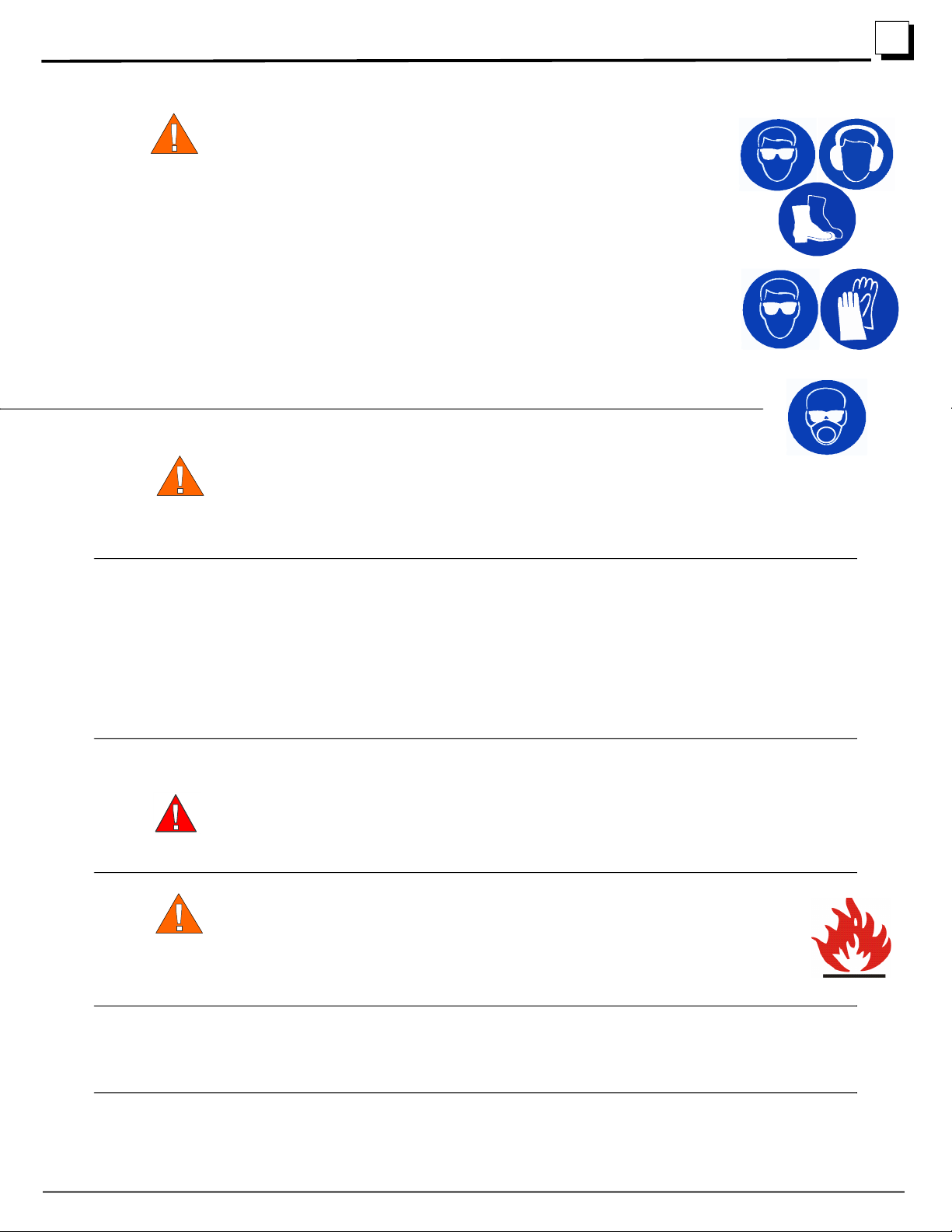
2.1 Safety Symbols ................................................................................................... 2-1
2.2 Safety Instructions............................................................................................... 2-1
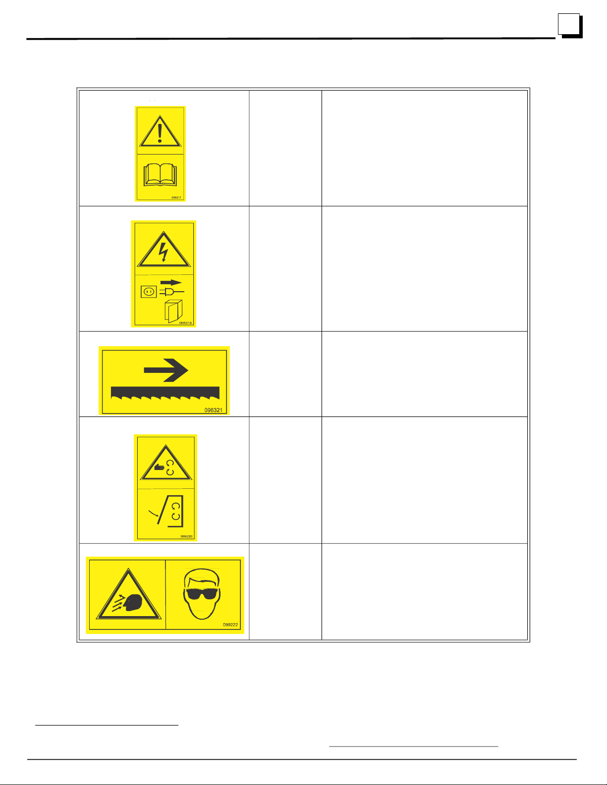
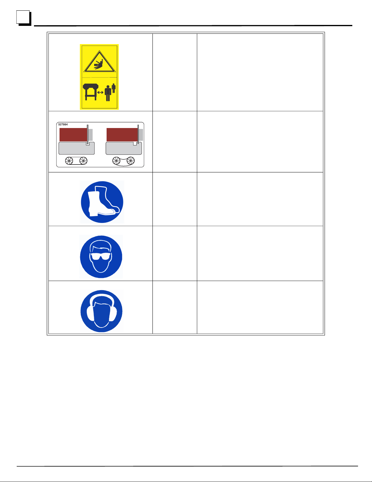
2.3 Safety Decals....................................................................................................... 2-4
SECTION 3 SETUP
3.1 Remove and inspect the parts boxes ................................................................... 3-1
3.2 Assemble the bed sections .................................................................................. 3-6
3.3 Level the bed....................................................................................................... 3-8
3.4 Install the mast .................................................................................................... 3-9
3.5 Install the sweepers and sawhead stops ............................................................ 3-11
3.6 Install the operator’s handle.............................................................................. 3-12
3.7 Install the Engine .............................................................................................. 3-12
3.8 Install the throttle cable..................................................................................... 3-14
3.9 Install the clutch cable ...................................................................................... 3-15
3.10 Assemble the up/down crank ............................................................................ 3-16
3.11 Install the scale.................................................................................................. 3-17
3.12 Install the dust chute ......................................................................................... 3-18
3.13 Install the Blade ................................................................................................ 3-18
3.14 Install the lube water tank ................................................................................. 3-20
SECTION 4 SAWMILL OPERATION
4.1 Sawmill adjustments ........................................................................................... 4-1
4.2 Starting the Engine/Motor................................................................................... 4-6
4.3 Loading, Turning, and Clamping Logs............................................................... 4-6
4.4 Level a Log ......................................................................................................... 4-7
4.5 Lift Operation...................................................................................................... 4-7
4.6 Engine Operation ................................................................................................ 4-7
4.7 Feed Operation.................................................................................................... 4-8
4.8 Cutting The Log.................................................................................................. 4-8
4.9 Edging ................................................................................................................. 4-9
4.10 Blade Height Scale.............................................................................................. 4-9
4.11 Water Lube Operation....................................................................................... 4-10
4.12 Transporting the Sawmill.................................................................................. 4-10
SECTION 5 MAINTENANCE
5.1 Continuous maintenance ..................................................................................... 5-1
5.2 General maintenance........................................................................................... 5-1
5.3 Engine maintenance ............................................................................................ 5-2
SECTION 6 SAWHEAD PARTS
6.1 Sliding Blade Guide Arm Assembly................................................................... 6-1

Table of Contents Section-Page
4 LX25 12/21/22 Table of Contents
6.2 Blade Guide Assembly........................................................................................6-2
6.3 Clutch Assembly .................................................................................................6-4
6.4 Scale and Sawdust Chute.....................................................................................6-5
6.5 Cover Hold-up Latch..........................................................................................6-6
6.6 Water Tank ..........................................................................................................6-7
6.7 Up/down Slides ...................................................................................................6-8
6.8 Winch .................................................................................................................6-9
6.9 Throttle Lever ...................................................................................................6-11
6.10 Blade Tension Assembly .................................................................................6-12
6.11 Band Wheel Assembly, Driver Side..................................................................6-13
6.12 Band Wheel Assembly, Idle Side......................................................................6-14
6.13 Sawhead Cover..................................................................................................6-15
6.14 Decals ................................................................................................................6-17
SECTION 7 ENGINE PARTS
7.1 Kohler 9hp Gas Engine ......................................................................................7-1
7.2 Kohler 7hp Gas Engine (G7-LX) ........................................................................7-2
SECTION 8 BED AND CARRIAGE ASSEMBLY
8.1 Bed.......................................................................................................................8-1
8.2 Log Clamp...........................................................................................................8-2
8.3 Carriage ...............................................................................................................8-3
8.4 Log Rest...............................................................................................................8-5
8.5 Optional Log Ramps............................................................................................8-6
8.6 Optional Adjustable Feet.....................................................................................8-7
8.7 Optional Log Taper Wedge ................................................................................8-8

Introduction
About This Manual 1
Introduction LX25 12/21/22 1-1
SECTION 1 INTRODUCTION
1.1 About This Manual
This manual replaces any previous information received on your Wood-Mizer® equipment.
The information and instructions in this manual do not amend or extend the limited warranties for the equipment given at the
time of purchase.
1.2 Getting Service
For contact information, sales, service, parts, and additional manuals, sign into your account on https://woodmizer.com, or call
inside the USA: 1-800-553-0182 or from outside the USA: 317-271-1542
1.3 Specifications
Equipment specification are included in the Online Manuals, which are found at https://apps.woodmizer.com/Manuals/Manu-
als.aspx?parent=0.
1.4 Dimensions
TDL-LX25

Safety
Safety Symbols
2
2-1 LX25 12/21/22 Safety
SECTION 2 SAFETY
2.1 Safety Symbols
The following symbols and signal words call your attention to instructions concerning your personal safety. Be sure to observe
and follow these instructions.
DANGER!indicates an imminently hazardous situation which, if not avoided, will result in serious
injury or death.
WARNING!suggests a potentially hazardous situation which, if not avoided, could result in serious
injury or death.
CAUTION!refers to potentially hazardous situations which, if not avoided, may result in minor or mod-
erate injury or damage to equipment.
NOTICE indicates vital information pertaining to equipment.
NOTE: contains useful information.
2.2 Safety Instructions
OWNER/OPERATOR'S RESPONSIBILITY
The procedures listed in this manual may not include all ANSI, OSHA, or locally required safety procedures. It is the
owner/operator’s responsibility and not Wood-Mizer LLC to ensure all operators are properly trained and informed of
all safety protocols. Owner/Operators are responsible for following all safety procedures when operating and performing
maintenance to the equipment.
Observe ALL Safety Instructions
NOTICE Read the entire Operator's Manual before operating this equipment.
Note all safety warnings throughout this manual and those posted on the machine.
Be able to access this manual at all times while operating this equipment.
Read additional manufacturer’s manuals and observe their applicable safety instructions.
Only persons who have read and understood the entire operator's manual should operate this equip-
ment.
This equipment is not intended for use by or around children.
It is the owner/operator's responsibility to comply with all applicable
federal, state, and local laws, rules, and regulations regarding the
ownership, operation, and transporting your equipment.
Operators should become thoroughly familiar with and comply with these
applicable laws for operating and transporting equipment.
WARNING!Clean sawdust from all guards, vents, control boxes, or any
area where sawdust may gather after every shift. Failure to do so may result in fire,
causing death or serious injury.

Safety
Safety Instructions 2
Safety LX25 12/21/22 2-2
Wear Safety Clothing (Personal Protection Equipment)
WARNING!Always wear eye, ear, and foot protection when operating or
servicing the sawmill.
Secure all loose clothing, hair, and jewelry before operating the sawmill.
Wear gloves and eye protection when handling bandsaw blades. Chang-
ing blades is safest when done by one person. Keep all other persons
away from area when coiling, carrying, or changing a blade.
Some woods require respiration protection when operating the sawmill. It
is the sawyer’s responsibility to know which woods require respira-
tion protection.
Keep Work Area Clean
WARNING!Clean sawdust from all guards, vents, control boxes, or any
area where sawdust may gather after every shift. Failure to do so may result in fire, causing death or
serious injury
Maintain a clean and clear path for all necessary movement around the equipment and lumber stacks.
NOTICE Always properly dispose of all sawing by-products, including sawdust and wood debris, cool-
ant, oil, fuel, oil filters, and fuel filters.
If replacing a component which has a safety decal affixed to it, make sure the new component also has
the safety decal affixed.
Inspect all safety decals to ensure they are clean and readable. Replace all damaged safety decals to
prevent personal injury or damage to the equipment. Contact your local distributor, or call your Cus-
tomer Service Representative to order more decals.
Fuel/Flammable Liquid Handling Safety
DANGER!Do not smoke, weld, grind, or otherwise create sparks near your engine or storage tanks,
especially during times of fueling.
Do not allow fuel/flammable liquid to spill on a heat source, such as a hot engine.
WARNING!Store gasoline away from sawdust and other flammable materials.
Do not use flammable liquids (diesel fuel or kerosene) in the water lube accesso-
ries.
Clean fuel/flammable liquid spills immediately.
NOTICE Remove blades from equipment before cleaning them with fuel/flammable liquid.
Dispose of fuel/flammable liquids per local ordinances.

Safety
Safety Instructions
2
2-3 LX25 12/21/22 Safety
Battery Safety
WARNING!Batteries expel explosive gases; keep sparks, flames, burning cigarettes, or other ignition
sources away at all times.
Wear safety goggles and a face shield when working near batteries.
Wash hands after handling batteries to remove possible lead, acid, or other contaminants.
Charge the battery in a well ventilated area.
Do not attempt to charge a frozen battery.
NOTICE When working with batteries, do not spill or splash electrolyte (dilute sulfuric acid) as it is a
strong corrosive.
Overcharging may reduce the overall service life of the battery.
Ensure the battery is fully charged before transporting the sawmill. If the battery is not fully charged,
excessive vibration could reduce the overall service life of the battery.
Sawmill Setup Safety
WARNING!Do not set up the mill on ground with more than a 10 degree incline. Setting up the mill on
an incline could cause it to tip over.
If setup on an incline is necessary, put blocks under one side of the mill or dig out areas for the legs to
keep mill level.
Use a lifting device (fork lift, crane, etc.) for parts over 100 lbs.
Use two persons for lifting parts over 50lbs.1
Keep all non-essential personnel out of the area while setting up the sawmill.
EMERGENCY TREATMENT FOR CONTACT WITH BATTERY COMPONENTS (LEAD/SULFURIC
ACID) per SDS (Safety Data Sheet):
EYE CONTACT Sulfuric Acid and Lead: Flush eyes immediately with large amounts
of water for at least 15 minutes while lifting lids. Seek immediate med-
ical attention if eyes have been exposed directly to acid.
SKIN CONTACT Sulfuric Acid: Flush affected area(s) with large amounts of water
using deluge emergency shower, if available, shower for at least 15
minutes. Remove contaminated clothing, including shoes. If symp-
toms persist, seek medical attention. Wash contaminated clothing
before reuse. Discard contaminated shoes.
Lead: Wash immediately with soap and water.
INGESTION Sulfuric Acid: Administer large amounts of water. Do NOT induce
vomiting or aspiration into the lungs may occur and can cause perma-
nent injury or death; consult physician.
INHALATION Sulfuric Acid: Remove to fresh air immediately. If not breathing, give
artificial respiration. If breathing is difficult, give oxygen. Consult a
physician.
Lead: Remove from exposure, gargle, wash nose and lips; consult
physician.

Safety
Safety Decals 2
Safety LX25 12/21/22 2-4
2.3 Safety Decals
1.For more information on lifting safety see NOISH Lifting Equation at https://www.cdc.gov/niosh/docs/94-110/
096317 Read Operator’s Manual
CAUTION! Thoroughly read the
manual before operating the
machine. Observe all safety instruc-
tions and rules when operating the
mill.
096319 Disconnect Power Supply Before
Opening
(Electric version only)
096321 Blade Movement Direction
099220 Sawmill Covers Caution
CAUTION! Close all guards and cov-
ers before starting the machine.
099222 Warning Projectile Hazard
Wear safety goggles.
50
100m

Safety
Safety Decals
2
2-5 LX25 12/21/22 Safety
099221 Keep Away Danger
CAUTION! Keep all persons a safe
distance away from work area when
operating the machine.
527864 Blade Tension
Align the disc in the notch for proper
blade tension.
501465 Use Safety Boots
Wear protective boots at all times
when operating the mill!
S12004g Use Eye Protection
Wear safety goggles at all times
when operating the mill!
S12005g Use Ear Protection
Wear ear protection at all times when
operating the mill!
0992 21B

Setup
Remove and inspect the parts boxes 3
Setup WM doc 12/21/223-1
SECTION 3 SETUP
3.1 Remove and inspect the parts boxes
Part # Description Part # Description Qty
Engine Manual 1 M2426 Manual Operator's/Parts 1
130360 Bag Kit, LX25 Fastener
(See next table) 1 X100-1050 Rod Lift Cable 2
C209 Black Brushed Bill Hat 1 X100-1056 Cable, Lift Paddle 2
X100-1057 Wrench, 7/8 Ratcheting 1
X100-1275 Plate, End Stop Lock 2 071015 Plate, 2012 LT10 Bed Rail
Clamp
4
X100-934 Plate, T100 Bed Coupler 4 X200-1027 Bracket, Log Post Top 5
X200-1045 Post, Log Rest (SHORT) 2 X200-1026 Post, Log Rest (LONG) 2

Setup
Remove and inspect the parts boxes
3
3-2 WM doc 12/21/22Setup
014151 Pin, 3/8x2 1/4 SQ Wire Lock 1 X200-1082 Clamp Assembly, Log Metric
(F05022-25 incl in bag kit)
1
X100-348 Bracket, Scale 1 046627 Handle, 33/64 ID x 1-1/4 OD x
4 PLASTIC (Sub 1)
1
X100-984 Block, Plastic Scale Timbery 2 F05011-123 Washer, 12mm Split Lock
(Sub 1)
1
F05010-212 Nut, M12x1.75 Free Zinc 1 F05027-19 Nut, M12-1.75 Zinc Jam 1
Part # Description Part # Description Qty

Setup
Remove and inspect the parts boxes 3
Setup WM doc 12/21/223-3
F05023-6 Bolt, M12-1.75x120 SHC 1 035248 Shim, .0075 Blade 1
X100-378 Sweeper, Modular Track 2 X100-1042 Hexagon Lift Cable 2
X100-970 Water Tank Assembly 1 X100-1020 Hook, Cover 1
F05011-45 Washer, 8mm Split Lock, Zn 2 F05004-47 Bolt, M8-1.25x16 HH Zinc 2
Part # Description Part # Description Qty

Setup
Remove and inspect the parts boxes
3
3-4 WM doc 12/21/22Setup
X100-929 Plate, T100 Drive/Idle Side
Rail
6 123031 Bracket, Center Bed Rail 6
X100-930 Plate, T100 Safety Catch Rail 3 X100-932 Plate, T100 Cross Brace 2
X100-202 Lower Carriage Member (w/
bearings installed)
2 X100-1044 Carriage Left Side Post 1
Part # Description Part # Description Qty

Setup
Remove and inspect the parts boxes 3
Setup WM doc 12/21/223-5
X100-1045 Wldmnt, Carriage Right Side
Pist
1 130947 Channel, Upright Cross 1
F05005-99 Bolt, M6-1.0x12 4 F05010-200 Nut, M601.0 Nylon 4
F05026-1 Washer, M6 Flat 6 F05089-3 Cable Ties 3
Part # Description Part # Description Qty

Setup
Assemble the bed sections
3
3-6 WM doc 12/21/22Setup
BAG KIT
3.2 Assemble the bed sections
WARNING!Assemble the bed on firm, level ground. Failure to do so may cause the
sawhead to tip, causing serious injury or death.
1. Assemble all of the bed sections using track
rails and cross rails, and one cross member
where each bed section joins together.See
FIG. 3-1.
a. Attach two cross rails per bed
section. Make sure to place the
cross rails closer together, leav-
ing room for the sawhead
assembly, as shown.
b. Attach the track rails to the cross
rail. Make sure all of the cross
rails face the same direction.
NOTE: Do not attach the catch rails at this time!
130360 BAG KIT, LX25 FASTENER QTY
F05022-25 Bolt, M10-1.5x120mm Hex Cl 8.8 2
F05022-3 Bolt, M10-1.5x30 Class 8 HH 70
F05022-17 Bolt, M10-1.5x70 Carriage 8
F05022-15 Bolt, M10-1.5x75 HH Class 8.8 4
F81003-125 Bolt, M10-1.5x85 Class 8 HH 4
F05020-7 Bolt, M6-1 x 14 Class 8 HH 3
F05020-6 Bolt, M6-1 x 20 Class 8 HH 4
F05020-8 Bolt, M6-1.0x30 Class8 HH 2
F05021-14 Bolt, M8-1.25x20 Carriage 2
F05021-29 Bolt, M8 x8mm SH Shoulder 2
F05027-47 Nut, M10-1.5 Flanged Nylon Lock 74
F05010-85 Nut, M10-1.5 Hex 8
F05004-270 Nut, M10-1.50 Hex Nyl Lock 4
F05010-162 Nut, M8-1.25 Free Zinc Plate 4
F05010-132 Nut, M8-1.25 Hex Nylock 4
F05026-4 Washer, M8 Flat 6
F05012-145 Pin, 1/4x2 1/2 Tab Lock 2
F05020-24 Screw, M6-1x8 SHSS 2
F05015-33 Screw,#10x3/4 Sl Hex Washer Hd Sht Metal 2
F05011-134 Washer, M10 Flat SAE 82
F05026-1 Washer, M6 Flat Class 4 11
F05026-2 Washer, M6 Split Lock 3
F05010-200 Nut, M6-1.0 Nylon Lock 6
TDLX2503-03
Track Rails
Cross Rails
Cross Member
Bolt, M10-1.5x30 HH
Class 8
Nut, M10-1.5 Flanged
Nylon Lock
Washer, M10 Flat
FIG. 3-1

Setup
Assemble the bed sections 3
Setup WM doc 12/21/223-7
2. Assemble the remaining track rails and cross rail in a similar fashion. See FIG. 3-2.
3. Connect the bed sections using a connecting plate, a clamp, and hardware.
a. Attach the connecting plate (X100-934) to each bed section, joining them together.
b. Tighten the side of the plate that has the fixed holes. Do not fully tighten the bolts (M10-1.5x30) on the side of
the plate that has slotted holes.
c. Set the clamp in place by inserting the larger notch first (on bottom) and then tilting the clamp in and upward
to catch the smaller notch (on top). See FIG. 3-3.
d. Tighten the bolts on the clamp (M10-1.5x85) to draw bed sections together.
NOTE: Be sure the track rails of each bed section are aligned before tightening the
plate bolts.
FIG. 3-3
TDLX2503-02
Direction of cut
FIG. 3-2
T100001-3
Smaller Notch
Larger Notch
Fixed Holes
Slotted Holes
Plate Bolts
Connecting Plate
Clamp
Bolt, M10-1.5x85, HH,
Class 8
Washer, M10 Flat
Nut, M10-1.5 Flanged
Nylon Lock
Washer, M10 Flat Nut, M10-1.5
Flanged Nylon Lock

Setup
Level the bed
3
3-8 WM doc 12/21/22Setup
e. Fully tighten the plate bolts in the slotted holes on
connecting plate.
NOTE: Be sure the slotted holes on
the connecting plate are connected
to the same bed section on both
sides of the bed frame.
f. Repeat for the remaining 3 connections.
g. Attach the cross member between the bed sec-
tions.
NOTE: Optional bed extension sec-
tions may be added at this time, in
the same manner as the standard
bed sections.
4. Attach the log clamp in the middle of the bed. See FIG. 3-4.
NOTE: The log clamp is shipped with two sets of bolts and spacers. Use the
shorter bolt and the long spacer only.
5. Attach the log rest brackets and posts. Do not tighten until the bed is leveled.
3.3 Level the bed
NOTE: It is important that the bed be level for the sawhead to travel smoothly over
the rails.
1. Mount the saw bed on wooden skids for leveling and increasing the ground clearance.
A straight 4x4 or 4x6 are an ideal size for the wooden skids. If the
skids are not a solid one-piece section, make sure the seams of
skids are offset from the seams of the bed frame. See FIG. 3-5.
2. Use a 4-foot level (or laser level) to level the bed in all
dimensions. See FIG. 3-6.
3. Adjust the bed for leveling by shimming under low spots.
NOTE: Failure to square the log
rest posts can result in poor cut
quality.
T100001-4
Washer, 3/8 Flat SAE
Log Clamp Spacer
Bolt, M10-1.5x120
Washer, 3/8 Flat SAE Nut, M10-1.50 Hex Nyl Lock
FIG. 3-4
T10002
Wooden Skid
1/2 x 3” Lag Bolts with
washer recommended
FIG. 3-5
T100001-6
Level
FIG. 3-6

Setup
Install the mast 3
Setup WM doc 12/21/223-9
4. When the bed is leveled, square up the log rest posts.
Tighten the log rest bracket screws. See FIG. 3-7.
5. Recheck saw bed for level!
3.4 Install the mast
Prepare the mast carriages
The sawhead carriages come mostly assembled from the
factory.
1. Place 4 carriage bolts from the hardware kit through
the inner side of the carriage.
2. Place washers and nuts loosely on the M10-1.5x70
carriage bolts. See FIG. 1-8.
NOTE: Do not tighten them at
this time.
3. Set the carriage on the rails.
NOTE: There is a bearing
for each side of the rail, and
the carriage rests on the
vertical bearing. The side
bearings are adjustable (slot-
ted holes), and must be
adjusted at this time. The ver-
tical bearings are not adjust-
able.See FIG. 3-9.
4. Adjust the bearings now so that the carriage glides
smoothly back and forth with little effort.
5. Repeat on the opposite side of the saw bed.
6. Remove the carriages from the rails for further installation with the mast.
1
0
0
B
-
0
0
2
Square
Log Rest Post
Log Rest Bracket
FIG. 3-7
T10003-6
Bolt, M10-1.5x70
Carriage
Washer, M10 Flat
Nut, M10-1.5 Hex
FIG. 3-8
Vertical Bearings
(highlighted green)
Rail
FIG. 3-9
Side Bearings
(highlighted red)

Setup
Prepare mast
3
3-10 WM doc 12/21/22Setup
Prepare mast
1. Insert the mast cross member into the upright pieces, as shown in FIG. 3-10.
2. Set the bolts in place as shown in FIG. 3-10.
NOTE: Do not tighten at this time.
Install the sawhead
1. Lay the sawhead flat on a surface high enough to
allow the carriages to extend downward (approxi-
mately 1ft (25cm)).
2. Slip the mast through the sawhead guides.
NOTE: Ensure that the
scale guide is on the
same side as the
up/down crank bracket.
3. Slide the mast uprights all the way into the car-
riages.
NOTE: Make sure that it
slides all the way to the
bottom of the carriage
and then tighten the M10-1.5x70 carriage bolts. See FIG. 3-11.
4. Install the two head-locking stop pins, locking the sawhead in the down position.
FIG. 3-10
Rod, Lift Cable
Nut, M8-1.25
Nylock
Bolt, M8x8 SH
Shoulder Plain
Nut, M8-1.25 Free
Hexagon, Lift Cable
Nut, M10-1.50
Bolt, M10-1.5x75
Engine Muffler Notch
Washer, M8 Flat
Upright Cross Channel
Carriage Post,
Right Side
Carriage Post,
Left Side
FIG. 3-11
Sawhead Guides
Scale Guides
Crank Bracket
Other manuals for LX25
1
Table of contents
Other woodmizer Power Tools manuals

woodmizer
woodmizer BMST50MU Guide

woodmizer
woodmizer Re-Sharp CBN-AC Guide

woodmizer
woodmizer LX450 Series Manual instruction

woodmizer
woodmizer BMS500 Guide

woodmizer
woodmizer BMT200 User manual

woodmizer
woodmizer BMST50 Series Guide

woodmizer
woodmizer LTAGA-PLCBN Guide

woodmizer
woodmizer CookieMizer CMJ User manual

woodmizer
woodmizer LTSC15S3 G18 User manual

woodmizer
woodmizer BMS25 Guide