woodmizer BMST50 Series Guide

Wood-Mizer® Sharpener
and Setter
Safety, Operation, Parts
& Maintenance Manual
BMST50 Rev. A.00- A.01
Safety is our #1 concern! Read and understand
all safety information and instructions before oper-
ating, setting up or maintaining this machine.
September 2014
Form #2057

ii BMST50doc100919 Table of Contents
Table of Contents Section-Page
SECTION 1 INTRODUCTION 1-1
1.1 About this manual...................................................................................................... 1-1
1.2 Safety......................................................................................................................... 1-2
Blade handling safety
Machine operation safety
Decal meaning
1.3 Major Components .................................................................................................... 1-5
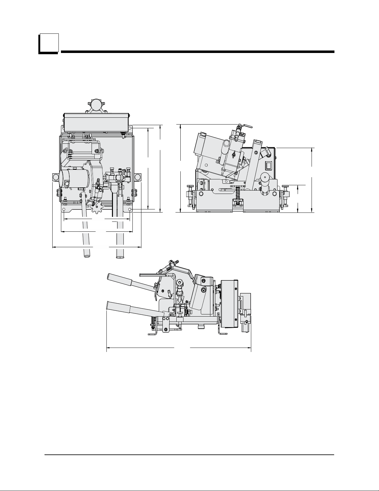
1.4 Dimensions and Specifications.................................................................................. 1-6
1.5 Getting Service .......................................................................................................... 1-7
General Contact Information
Wood-Mizer Locations
SECTION 2 SET UP 2-1
2.1 Items required but NOT included.............................................................................. 2-1
2.2 Items included ........................................................................................................... 2-2
2.3 Install the lubrication pump....................................................................................... 2-3
2.4 Mount the base unit ................................................................................................... 2-4
2.5 Install the drain pipe .................................................................................................. 2-4
2.6 Install the operators handles ...................................................................................... 2-5
2.7 Mount the blade supports .......................................................................................... 2-5
2.8 Install grinding wheel................................................................................................ 2-7
2.9 Power cord................................................................................................................. 2-7
2.10 Calibrate the set gauge............................................................................................... 2-8
SECTION 3 OPERATION 3-1
3.1 Blade introduction ..................................................................................................... 3-1
3.2 Rejecting blades......................................................................................................... 3-2
3.3 Install the grinding wheel .......................................................................................... 3-2
3.4 Blade installation....................................................................................................... 3-2
3.5 Sharpening ................................................................................................................ 3-3
Prior to 6/28/2015
After 6/28/2015
3.6 Blade Sharpening Tips ........................................................................................... 3-10
3.7 Deburr the blade after sharpening ........................................................................... 3-10
3.8 Setting the blade ...................................................................................................... 3-10
3.9 Checking the set ...................................................................................................... 3-12
3.10 Quick check of the set ............................................................................................. 3-13

Table of Contents Section-Page
Table of Contents BMSTdoc100919 iii
SECTION 4 MAINTENANCE 4-1
4.1 Maintaining your Sharpener & Setter........................................................................ 4-1
4.2 Grinding wheel replacement...................................................................................... 4-1
4.3 Grinding Oil............................................................................................................... 4-2
4.4 Periodic maintenance................................................................................................. 4-2
4.5 Adjusting the grinding angle ..................................................................................... 4-3
SECTION 5 REPLACEMENT PARTS 5-1
5.1 How To Use The Parts List ....................................................................................... 5-1
5.2 Sample Assembly ...................................................................................................... 5-1
5.3 Base Assembly .......................................................................................................... 5-2
5.4 Sharp/Set Block Assemblies...................................................................................... 5-4
5.5 Push Pawl Assembly ................................................................................................. 5-5
5.6 After 6/28/2015 Main Block Assembly .................................................................... 5-7
Main block assembly
Prior to 6/28/2015
5.7 Sharpener Plate.......................................................................................................... 5-9
5.8 Setter Clamp Assembly ........................................................................................... 5-10
5.9 Sharpener Motor Assembly..................................................................................... 5-11
5.10 Motor Mount ........................................................................................................... 5-12
5.11 Control Handles....................................................................................................... 5-14
5.12 Blade Support .......................................................................................................... 5-15
5.13 Lube System ............................................................................................................ 5-16
5.14 Electrical Panel ..................................................................................................... 5-18
5.15 Component Layout .................................................................................................. 5-21
5.16 Component List ....................................................................................................... 5-21
INDEX I


Introduction
About this manual
Introduction BMST50doc100919 1-1
1
SECTION 1 INTRODUCTION
1.1 About this manual
Congratulations on your purchase of a Wood-Mizer Sharpener & Setter! When properly
maintained and operated, your Sharpener & Setter should give you many years of
dependable service.
This manual does not cover every possible operation and safety issues that may occur
while using this equipment. This manual covers some of the basic safety procedures
relating to sawblade maintenance but common sense should take precedence over this
manual. Operators should follow safety procedures at all times.
The information and instructions given in this manual do
not amend or extend the limited warranties for the equip-
ment given at the time of purchase.
CAUTION! Read this entire manual before
operating the equipment. Take notice of all
safety warnings throughout this manual and
those posted on the equipment. Keep this
manual with this equipment at all times,
regardless of ownership.
Only persons who have read and understood the entire operator's manual should operate
the Sharpener & Setter. The Sharpener & Setter is not intended for use by or around chil-
dren.

Introduction
Safety
1-2 doc100919 Introduction
1
1.2 Safety
The triangle symbol calls your attention to instructions concer n i n g y ou r p e r s o n al sa f e t y.
Read and follow these instructions!
DANGER INDICATES AN IMMINENTLY HAZARDOUS SITUATION WHICH, IF
NOT AVOIDED, WILL RESULT IN SERIOUS INJURY OR DEATH.
WARNING! Suggests a potentially hazardous situation which, if
not avoided, may result in serious injury or death.
CAUTION!! Refers to potentially hazardous situations which, if
not avoided, may result in minor or moderate injury to persons
or equipment damage.
NOTE: Informs people of important installation, operation,
or maintenance information that is not hazard related.
Read and observe all safety instructions before operating this equipment!
Always be sure that all safety decals are clean and readable. Replace all damaged safety
decals to prevent personal injury or damage to the equipment. Contact your local distribu-
tor, or call your Customer Service Representative to order more decals.
Blade handling safety
WARNING! Always wear gloves and eye protection when han-
dling bandsaw blades. Keep all persons away from area when
coiling or carrying a blade.
WARNING! Before installing the blade, inspect it for damage and
cracks. Always handle the blade with extreme care. Use suitable
carrier equipment for transporting the blades.
Machine operation safety
DANGER MAKE SURE ALL GUARDS AND COVERS ARE IN PLACE
AND SECURED BEFORE OPERATING THIS MACHINE. FAILURE
TO DO SO MAY RESULT IN SERIOUS INJURY.
DANGER KEEP ALL PERSONS AWAY FROM MOVING PARTS WHEN OPERAT-
ING THIS MACHINE. FAILURE TO DO SO WILL RESULT IN SERIOUS
INJURY.
DANGER ALWAYS KEEP HANDS AWAY FROM MOVING BANDSAW BLADE.
FAILURE TO DO SO WILL RESULT IN SERIOUS INJURY.

Introduction
Safety
Introduction BMST50doc100919 1-3
1
WARNING! Always wear eye protection when operating this
machine. Failure to do so may result in serious injury.
WARNING! Secure all loose clothing and jewelry before operating
this machine. Failure to do so may result in serious injury.
WARNING! This machine should be operated only by adults who
have read and understood the entire operator’s manuals.
WARNING! The illumination at the operator’s position should be at
least 300 lux. The light source may not cause stroboscopic effect.
Decal meaning
TABLE 1-0
Decals View Description
096317
Carefully read the operator’s
manual before operating the
machine. Observe all safety
instructions and rules when
operating.
096316
Opening of the electric box is
possible only when the switch is in
the ”0” position.

Introduction
Safety
1-4 doc100919 Introduction
1
096321
Blade movement direction
S12004G
Always wear eye protection
equipment when operating this
machine.
S12005G
Always wear ear protection
equipment when operating this
machine.
512107
Always wear safety gloves when
operating this machine.
TABLE 1-0

Introduction
Major Components
Introduction BMST50doc100919 1-5
1
1.3 Major Components
This Sharpener & Setter should only be used with a 1" to 1-1/2" blades with a 7/8" tooth
spacing. The figure below shows the major components of the Sharpener & Setter. These
terms will be used throughout this manual to refer to these major components. See Fig. 1-1
BMST50-100
FIG. 1-1
Set control
handle
Base assembly
Set block
Blade height
adjustment
Sharpener control
handle
Sharpener control
handle
Motor
Electrical panel
Lube hose
Electrical panel
Lubrication pump
Motor
Advancement
handle
Blade clamp
lever
Advancement
position knobs
Blade support
Main power
Grinder/Oil
pump power

Introduction
Dimensions and Specifications
1-6 doc100919 Introduction
1
1.4 Dimensions and Specifications
Grinding Motor: 1/7th HP
Grinding Wheel: 5” CBN
Blade Capacity: 1-1/4” and 1-1/2” with 7/8 Pitch
Operation: Manual
Production Capacity: Individual
Power: 100-240V AC, 50/60 Hz
26.75in
679.4mm
16.14in
410.0mm
13.0in
330.2mm
12.0in
330.2mm
14.620in
371.3mm
13.62in
345.9mm 12.73in
323.4mm 9.32in
236.7mm
4.0in
101.6mm
BMST50-DIM

Introduction
Getting Service
Introduction BMST50doc100919 1-7
1
1.5 Getting Service
Wood-Mizer is committed to providing you with the latest technology, best quality and
strongest customer service available on the market today. We continually evaluate our
customers’ needs to ensure we’re meeting current wood-processing demands. Your
comments and suggestions are welcome.
General Contact Information
Toll free phone numbers are listed below for the continental U.S. and Canada. See the
next page for contact information for more Wood-Mizer locations.
Office Hours: All times are Eastern Standard Time.
Please have your vehicle identification number and your customer number ready when
you call.
Wood-Mizer will accept these methods of payment:
Visa, Mastercard, or Discover
COD
Prepayment
Net 15 (with approved credit)
Be aware that shipping and handling charges may apply. Handling charges are based on
size and quantity of order. In most cases, items will ship on the day they are ordered.
Second Day and Next Day shipping are available at additional cost.
If your sawmill was purchased outside the United States or Canada, contact the distribu-
tor for service.
United States Canada
Sales 1-800-553-0182 1-877-866-0667
Service 1-800-525-8100 1-877-866-0667
Website www.woodmizer.com www.woodmizer.ca
E-mail woodmizer@woodmizer.com oninfo@woodmizer.com
Monday - Friday Saturday
(Indianapolis Office Only)
Sunday
8 a.m. to 5 p.m. 8 a.m. to 12 p.m. Closed

Introduction
Wood-Mizer Locations
1
1-8 BMST50doc100919 Introduction
Wood-Mizer Locations
USA World Headquarters Canadian Headquarters
Serving North & South America, Oceania, East Asia
Wood-Mizer LLC
8180 West 10th Street
Indianapolis, IN 46214
Phone: 317.271.1542 or 800.553.0182
Customer Service: 800.525.8100
Fax: 317.273.1011
Email: infocenter@woodmizer.com
Serving Canada
Wood-Mizer Canada
396 County Road 36, Unit B
Lindsay, ON K9V 4R3
Phone: 705.878.5255 or 877.357.3373
Fax: 705.878.5355
Email: ContactCanada@woodmizer.com
Brazil Headquarters Europe Headquarters
Serving Brazil
Wood-Mizer do Brasil
Rua Dom Pedro 1, No: 205 Bairro: Sao Jose
Ivoti/RS CEP:93.900-000
Tel: +55 51 9894-6461/ +55 21 8030-3338/ +55 51
3563-4784
Email: info@woodmizer.com.br
Serving Europe, Africa, West Asia
Wood-Mizer Industries Sp z o.o.
Nagorna 114
62-600 Kolo, Poland
Phone: +48.63.26.26.000
Fax: +48.63.27.22.327
Branches & Authorized Sales Centers
For a complete list of dealers, visit www.woodmizer.com

Set up
Items required but NOT included
Set up BMST50doc100919 2-1
2
SECTION 2 SET UP
2.1 Items required but NOT included
Table
Mounting screws
Oil Bucket
Sharpening Oil (Grinding oil CE-150)
5 inch grinding wheel
Tools:
Drill
Drill bits/hole saw up to 2 in (50mm)
#2 Phillips screwdriver
You will need a sturdy table top on level
surface on which to mount the Sharpener &
Setter base unit and the blade supports.
The table must be large enough to hold a
saw blade (a 4x8 ft (1200x 2400mm) sheet
works well). The illustration to the right
shows approximate locations of the equip-
ment’s footprint on the 4x8 ft
(1200x2400mm) table. Fig. 2-1
Dimentions for drilling mounting holes are
shown in Bottom View Fig. 2-2 .
A standard 5-gallon (or 20 l) bucket placed
directly under the table can be used for oil
recirculation. The drain pipe should not
extend so close to the bottom of the bucket
that it inhibits drainage.
2 in
50 mm
9-10 in
230-250 mm
SS20-14
Center
line
FIG. 2-1
Front
304.8mm
12.0in
152.4mm
6.0in
345.4mm
13.6in
SS20-24
FIG. 2-2 BOTTOM VIEW
Front

Set up
Items included
2-2 doc100919 Set up
2
2.2 Items included
See Fig. 2-3
1. SS20-985 Pump Assembly with
F05015-27 Screws (4 pcs):
2. 074368 Hose Clamp (2 pc):
3. R01885 Tubing (4 ft included to be cut
to length as needed)
4. P31347 Magnet, Filter (1 pc)
5. SS20-968 Drain Pipe
6. 069666 Power Cord
7. SS20-964 Blade Guard
8. SS20-969 Blade Support Assemblies
(3)
9. SS20-972 Sharpener Handle Assem-
bly
10. SS20-200 Set Handle and 066111 Set
Handle Grip
11. SS20-999 Angle Gauge
12. 060490 Set Gauge
13. 004754 Set Correction Tool
14. SS20-331 Quick Set Check Tool
BMST
50-15
FIG. 2-3

Set up
Install the lubrication pump
Set up BMST50doc100919 2-3
2
2.3 Install the lubrication pump
Use a Phillips head screwdriver to install the pump on the rear of the electrical panel with
the 4 screws provided.
Slide the hose clamps over the lube hose. Leave enough room that the hose can seat
itself all the ways on the pump fittings
Push the lube hose onto the pump fittings on both sides of the pump. Secure the hoses
on the fittings using the hose clamps provided. You may need plyers for this.
Ensure that the hoses are well seated and secure on the fittings. See Fig. 2-4
Route the supply hose into the oil bucket. With a cutting tool, cut the supply hose to
slightly above the bottom of the bucket.
Connect the two power wires extending from the bottom center of the electrical box to the
mating wires on the pump.
SS20-17WM
FIG. 2-4
Supply hose
Motor hose Supply hose
Motor hose

Set up
Mount the base unit
2-4 doc100919 Set up
2
2.4 Mount the base unit
The table will need a 2 inch (50 mm) hole to allow for an oil drain pipe to extend through it
into a bucket placed under the machine. An optional 1 inch (25 mm) hole could be also be
drilled for the oil supply hose, if desired. Location of the drain hole is not precise; it may
go where the operator feels most comfortable.
Align the base unit so that the drain fitting sets into the hole in the table you have pro-
vided. When the unit is aligned with the table, bolt the base unit to the table with screws
you provide. See Fig. 2-5
2.5 Install the drain pipe
Place the discharge end of the drain
pipe into the oil bucket first. Simply
screw in the threaded pipe into the
drain fitting at the bottom of the pan.
Place the filter magnet into the bottom
of the oil bucket near the drain output.
See Fig. 2-6
BMST50-18
FIG. 2-5
FIG. 2-6
BMST50-19

Set up
Install the operators handles
Set up BMST50doc100919 2-5
2
2.6 Install the operators handles
For the set handle, rotate the handle from the shipping position to the forward position.
See Fig. 2-7
For the sharpener handle, place the nuts and bolt of the handle in the position shown in
Fig. 2-7 . Two washers and the nuts go on the inside of the sharpener housing. Tighten
both nuts.
2.7 Mount the blade supports
Place the first blade guide on the table in line with the back side of sharpener. Locate it
near the outside edge of the table. Orient the groove so the blade slides through parallel
to the sharpener. See step 1 in Fig. 2-8 . Fasten the blade guide to the table with your
own screws.
WARNING! Always wear gloves and eye protection when handling
bandsaw blades. Changing blades is safest when done by one per-
son! Keep all other persons away from area when coiling, carrying
or changing a blade. Failure to do so may result in serious injury.
BMST50-20
FIG. 2-7
BMST50-21

Set up
Mount the blade supports
2-6 doc100919 Set up
2
Install a blade in the sharpener and rear guide so that the blade forms an oval shape. See
step 2 in Fig. 2-8 . Adjust the height of the rear guide so the bottom of the blade is
approximately level with the blade’s bottom in the sharpener.
Place a second guide to the right side of the base
unit, approximately 18 – 24 inches (450 – 600mm)
away along the curvature of the blade. Orient the
groove so the blade will slide through with minimal
pressure against the sides. Adjust the height of the
blade guide groove so that the blade does not touch
the bottom of the groove. See Fig. 2-9 Side Sup-
ports. Fasten the blade guide to the table with your
own screws. See step 3 in Fig. 2-8 .
Repeat on left side. See step 4 in Fig. 2-8 .
Install the blade guard on the table to the right of the
base unit. The blade guard helps prevent inadvertent
operator contact with the blade teeth during operation. Make sure that it is far enough
away from the blade that it does not touch at any point. See step 5 in Fig. 2-8 . Fasten
the blade guide to the table with your own screws.
BMST50-22
FIG. 2-8
Step 2
Step 4
Step 1
Step 5
Step 3
18-24 in
450-600 mm
SS20-25
Gaps, if
possible
Gap
FIG. 2-9 SIDE SUPPORTS
Adjustment
nuts

Set up
Install grinding wheel
Set up BMST50doc100919 2-7
2
2.8 Install grinding wheel
Loosen the three nuts on the grinder motor housing and remove the housing plate.
Loosen the nut on the grinder motor shaft and remove the washer. Place the wheel on the
shaft under the washer, then tighten the motor shaft nut. Reinstall the housing plate. See
Fig. 2-10 .
2.9 Power cord
Insert the power cord into the power recepticle on the lower left side of the electrical
panel. The cord is keyed so that it will fit in only one orientation. Plug the other end into a
standard grounded outlet. See Fig. 2-11
BMST50-26
FIG. 2-10
SS20-23
FIG. 2-11

Set up
Calibrate the set gauge
2-8 doc100919 Set up
2
2.10 Calibrate the set gauge
The tooth set gauge accurately measures the set of any blade tooth. The gauge needs to
be assembled and calibrated before use.
Refer to Fig. 2-12 . Insert the dial gauge assembly into the hole in the block housing.
Clamp the calibrating pin in position at the center of the dial gauge foot. (See SIDE VIEW.)
Push the gauge assembly forward until the foot just touches the pin and dial needle
moves .005 to .010. Tighten the locking screw with the provided hex wrench (do not
over-tighten). Loosen the dial lock on the gauge and rotate the dial face until the needle
reads 0.00. Tighten the dial lock.
Unclamp the calibrating pin from the set gauge clamp by turning the clamp knob counter-
clockwise. With the pin not clamped, the set gauge needle should read between -.005
and -.010. If not, reclamp the pin, loosen the locking screw and move the set gauge
assembly back so the foot does not contact the pin. Repeat the steps above until the dial
needle reads zero with the calibrating pin clamped and between -.005 and -.010 without
the pin clamped. This ensures the dial foot extends beyond the clamp plate a small
amount and will read zero when the foot is aligned with the clamp plate.
BMST50-43
Calibrating pin
(See side view)
Clamp knob
Dial gauge
assembly
Dial lock
Locking
screw
Clamp
plate
Gauge foot
Pin
Block housing
SIDE VIEW
Rest pin
Rest pin lock
knob
FIG. 2-12
Dial lock
Table of contents
Other woodmizer Power Tools manuals

woodmizer
woodmizer LT60HD Manual instruction

woodmizer
woodmizer LTAGA-PLCBN Guide

woodmizer
woodmizer Re-Sharp CBN-AC Guide

woodmizer
woodmizer MP100 E11-R User manual

woodmizer
woodmizer BMT200 User manual

woodmizer
woodmizer BMST50MU Guide

woodmizer
woodmizer LX450 Series Manual instruction

woodmizer
woodmizer LT15WC E15 User manual

woodmizer
woodmizer STRB-S Guide

woodmizer
woodmizer LTAGA Guide
Popular Power Tools manuals by other brands

Nation Flooring Equipment
Nation Flooring Equipment 6280 series quick start guide

Bosch
Bosch GOP 18 V-EC professional Original instructions

Stahlwille
Stahlwille Standard Manoskop 720 Nf/80 instructions

Makita
Makita DTM40 instruction manual

YATO
YATO YT-09515 Original instructions

DeWalt
DeWalt DCS496 instruction manual