woodmizer LTAGA-PLCBN Guide

LTAGA-PLCBN SHARPENER
Safety, Operation, Maintenance
& Parts Manual
097032 rev. A.00
Safety is our #1 concern! Read and understand
all safety information and instructions before oper-
ating, setting up or maintaining this machine.
August 2001 Form #944
!

Table of Contents Section-Page
2 CBNdoc063008 Table of Contents
SECTION 1 SAFETY & GENERAL INFORMATION 1-1
1.1 Electrical Safety.........................................................................................................1-2
1.2 Blade Handling..........................................................................................................1-2
1.3 Machine Operation....................................................................................................1-3
1.4 Sharpener Components.............................................................................................. 1-4
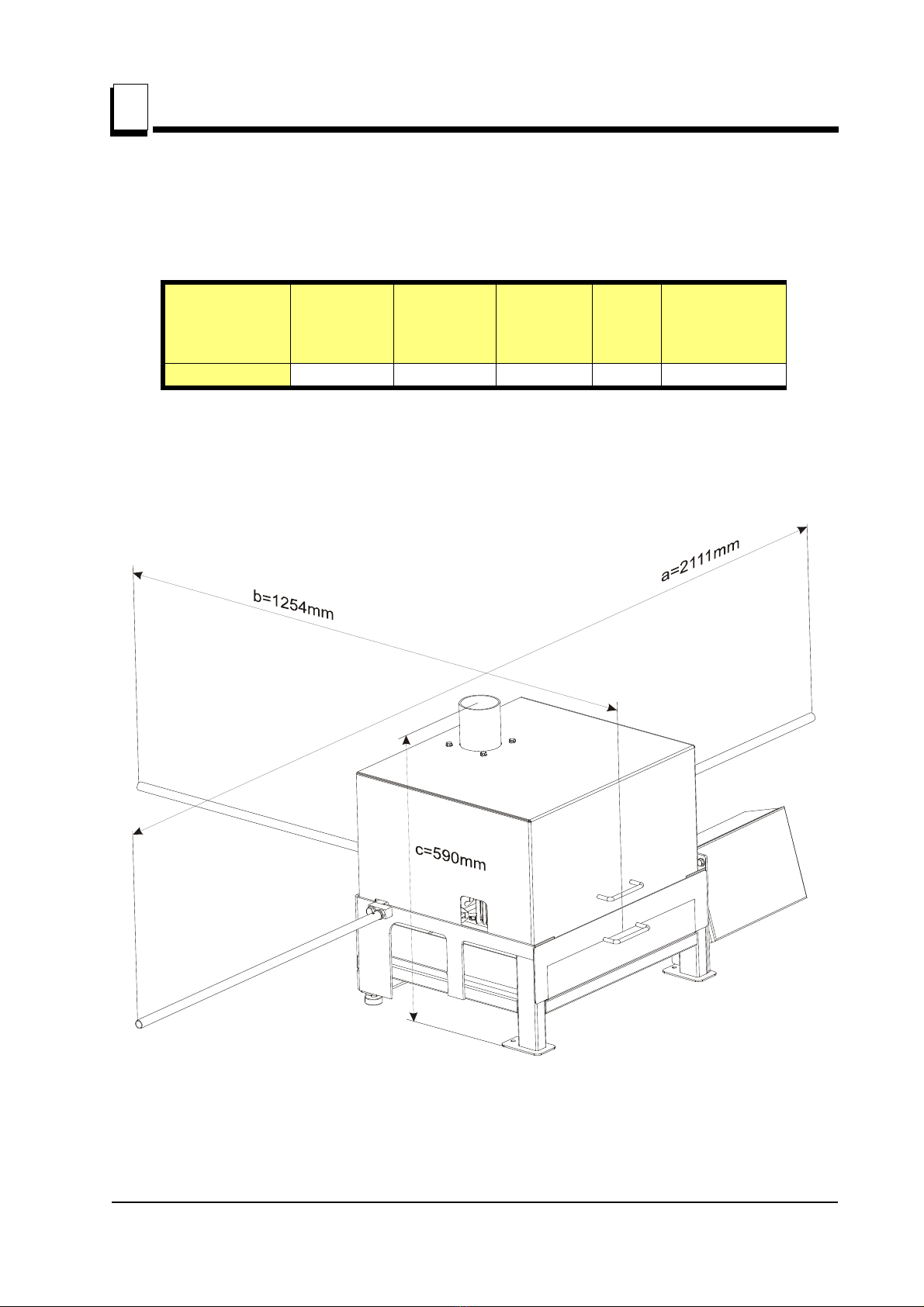
1.5 Overall Dimensions and Other Technical Data......................................................... 1-5
1.6 Noise Level................................................................................................................ 1-6
1.7 Motor Specifications .................................................................................................1-6
1.8 Coolant Specifications............................................................................................... 1-6
1.9 Control Panel Components........................................................................................1-7
1.10 Warning Decals Description......................................................................................1-9
SECTION 2 SETUP & OPERATION 2-1
2.1 Machine Start.............................................................................................................2-1
2.2 Blade Support Installation......................................................................................... 2-2
2.3 Blade Height Adjustment.......................................................................................... 2-3
2.4 Sharpener Alignment.................................................................................................2-4
2.5 Grinding Wheel Installation...................................................................................... 2-6
2.6 Blade Installation....................................................................................................... 2-7
2.7 Face Grind Adjustment.............................................................................................. 2-9
2.8 Grind Depth Adjustment .........................................................................................2-12
2.9 Oil Flow Adjustment...............................................................................................2-13
2.10 Feed Rate Adjustment .............................................................................................2-13
2.11 Magnetic Shut-off....................................................................................................2-13
2.12 Blade Rejection .......................................................................................................2-14
2.13 Operation Overview ................................................................................................2-15
2.14 Shutoff.....................................................................................................................2-15
SECTION 3 MAINTENANCE 3-1
3.1 Grinding Wheel Replacement ................................................................................... 3-1
3.2 Oil Level....................................................................................................................3-1
SECTION 4 MAINTENANCE & TROUBLESHOOTING 4-1
4.1 Sharpener Maintenance ............................................................................................. 4-1
4.2 Blade Sharpening Tips .............................................................................................. 4-2
SECTION 5 ALIGNMENT 5-1

Table of Contents Section-Page
Table of Contents
SECTION 6 REPLACEMENT PARTS 6-1
6.1 How To Use The Parts List...................................................................................... .6-1
6.2 Blade Support Assembly .......................................................................................... 6-2
6.3 Grinder Asembly ....................................................................................................... 6-3
6.4 Sharpener Mounting Plate.........................................................................................6-5
6.5 Blade Clamp Assembly............................................................................................. 6-6
6.6 Oil Pump/Pan.............................................................................................................6-8
6.7 Cam Assembly........................................................................................................... 6-9
6.8 Cover Assembly ......................................................................................................6-11
6.9 Alignment tool.........................................................................................................6-12
SECTION 7 ELECTRICAL INFORMATION 7-1
7.1 Electrical Symbol Diagram .......................................................................................7-1
7.2 Electrical Component List......................................................................................... 7-2
7.3 Component Layout Diagram..................................................................................... 7-2

Manufacturer Data:
Wood-Mizer Industries, Ltd.
Nagórna 114
62-600 Koło
Poland
Tel. +48 63 26 26 000
If You Need To Order Parts...
From Europe call our European Headquarters and Manufacturing Facility in Kolo, Poland
at +48-63-2626000. Wood-Mizer will accept the folowing methods of payment:
• Visa, Mastercard, or Select Purchase
•COD
• Prepayment
• Net 15 (with approved credit)
Be aware that shipping and handling charges may apply. Handling charges are based on
size and quantity of order. In most cases, items will ship on the day they are ordered.
Second Day and Next Day shipping are available at additional cost.

If You Need Service...
From Europe call our European Headquarters and Manufacturing Facility in Kolo, Poland
at +48-63-2626000.Ask to speak with a Customer Service Representative. Please have
your customer number ready when you call. The Service Representative can help you
with questions about alignment of your equipment. He also can schedule you for
a service call.
Office Hours: All times are Eastern Standard Time.
IMPORTANT! Read the entire Operator's Manual before
operating the conveyor. Take notice of all safety warnings
throughout this manual and those posted on the equipment.
Keep this manual with this equipment at all times,
regardless of ownership.
*Wood-Mizer®is a registered trademark of Wood-Mizer Products, Inc.
Country Monday - Friday Saturday Sunday
Poland 8 a.m. to 4:30 p.m. 8 a.m. to 1 p.m. Closed
!

Safety & General Information
1
1-1 ISHdoc063008 Safety & General Information
SECTION 1 SAFETY & GENERAL INFORMATION
This symbol calls your attention to instructions concerning your personal safety. Be sure
to observe and follow these instructions. This symbol accompanies a signal word.
The word DANGER indicates an imminently hazardous situation which, if not avoided,
will result in death or serious injury. WARNING suggests a potentially hazardous situation
which, if not avoided, could result in death or serious injury. CAUTION refers to potentially
hazardous situations which, if not avoided, may result in minor or moderate injury to
persons or equipment. Read all safety instructions before operating this equipment
and observe all safety warnings!
Warning stripes are placed on areas where a single decal would be insufficient. To avoid
serious injury, keep out of the path of any equipment marked with warning stripes.
Read and observe all safety instructions before operating this equipment! Also read any
additional manufacturer’s manuals and observe any applicable safety instructions
including dangers, warnings, and cautions.
Always be sure that all safety decals are clean and readable. Replace all damaged safety
decals to prevent personal injury or damage to the equipment. Contact your local
distributor, or call your Customer Service Representative to order more decals.
Always properly dispose of all by-products, including debris, coolant and oil.
Safety instructions are listed in this section by the following operations:
Electrical Safety
Blade Handling
Machine Operation

Safety & General Information
Electrical Safety
Safety & General Information ISHdoc063008 1-2
1
1.1 Electrical Safety
DANGER! Make sure all electrical installation, service
and/or maintenance work is performed by a qualified
electrician and is in accordance with applicable electrical
codes.
DANGER! HAZARDOUS VOLTAGE can cause shock,
burns, or death. SHUT OFF & LOCK OUT POWER before
performing service in any area of this machine. DO NOT
restore power until all access panels are replaced
and secured.
WARNING! Always turn off and disconnect power at control
console AND at main supply circuit breaker before
performing any service to the machine.
1.2 Blade Handling
WARNING! Always wear gloves and eye protection when
handling bandsaw blades. Keep all persons away from
area when coiling or carrying a blade (4 meters at least).

Safety & General Information
Machine Operation
1
1-3 ISHdoc063008 Safety & General Information
1.3 Machine Operation
DANGER! Make sure all guards and covers are in place
and secured before operating the sharpener. Failure to do
so may result in serious injury.
DANGER! Keep all persons away from moving parts when
operating this machine (2 meters at least). Failing to do so
will result in serious injury.
DANGER! Always keep hands away from moving bandsaw
blade. Failure to do so will result in serious injury.
WARNING! Always wear eye, ear, respiration, and foot
protection when operating this machine. Failure to do so
may result in serious injury.
WARNING! Secure all loose clothing and jewelry before
operating this machine. Failure to do so may result in
serious injury or death.
WARNING! The sharpener should not be operated by
persons allergic to ACP-1 oil or its vapors.
CAUTION! The sharpener’s work-stand should be
equipped with a 4 kg or bigger dry powder extinguisher.

Safety & General Information
Sharpener Components
Safety & General Information ISHdoc063008 1-4
1
1.4 Sharpener Components
The LTAGA-PLCBN sharpener is designed for sharpening only Wood-Mizer blades with
9.29, 10.30, 13.29 and 4.32 profiles.
See Figure 1-1. The major components of the sharpener are shown below.
FIG. 1-1
CBNSH03C
Blade Support Arms
Cam Index Assembly
Grinder
Assembly
(Sharpener
Head)
Clamp
Assembly
Oil Pan/Filter Magnets
Control Box

Safety & General Information
Overall Dimensions and Other Technical Data
1
1-5 ISHdoc063008 Safety & General Information
1.5 Overall Dimensions and Other Technical Data
See Table 1-1. The overall dimensions and the weight of the PLCBN sharpener (without
the blade support arms) are listed below.
See Figure 1-2. The figure below shows the overall dimensions of the PLCBN sharpener
with the blade support arms installed.
Model Length Width Height Weight Weight of
sharpener
packaged in
carton
LTAGA-PLCBN 627mm 845mm 590mm 83kg 90kg
TABLE 1-1
FIG. 1-2
CBNSH36B

Safety & General Information
Noise Level
Safety & General Information ISHdoc063008 1-6
1
1.6 Noise Level
See Table 1-2. The noise level produced by the LTAGA-PLCBN sharpener is given
below 1.
1.7 Motor Specifications
See Table 1-3. The grinder motor specifications are listed below.
1.8 Coolant Specifications
See Table 1-4. The table below lists the coolant specifications.
Noise Level
LTAGA-PLCBN 74,5 dB (A)
TABLE 1-2
1. The measured values refer to emission levels, not necessarily to noise levels in the
workplace. Although there is a relation between emission levels and exposure levels, it is
not possible to determine with certainty if preventives are needed or are not needed. The
factors affecting a current level of noise exposure during work are inter alia room
characteristics and characteristics of other noise sources, e.g. number of machines and
machining operations nearby. Also, the permissible exposure level value may vary
depending on country. This information enables the machine’s user to better identify
hazards and a risk .
Motor Manufacturer Model Power Other data
Electric Besel, Poland SEKg 56 2C2 0.18kW 1.5 A, 2800 r.p.m.
TABLE 1-3
Oil Type Manufac-
turer
Freezing Point Flash
Point
Autoignition Point
ACP-1E 1
1 Waste oil must be disposed of in complance with applicable state and local regulations.
Orlen -20 C Above
140 C 250 C
TABLE 1-4
°
°
°

Safety & General Information
Control Panel Components
1
1-7 ISHdoc063008 Safety & General Information
1.9 Control Panel Components
See Figure 1-3. The control panel components and their descriptions are shown below.
FIG. 1-3
Feed Rate Dial
Emergency
Stop
Disconnect
Switch
Cam Motor
Start/Stop Switch
Grinder
Motor/Stop Switch
Coolant Pump
Start/Stop Switch

Safety & General Information
Control Panel Components
Safety & General Information ISHdoc063008 1-8
1
Disconnect button
Turns on/off the sharpener power and the oil pump.
Press the START Button to turn the sharpener power on. Press the STOP Button to
turn the sharpener power off.
To reconnect power to equipment, turn switch to the "1", or horizontal, position.
Feed Rate Dial
Controls cam speed.
Rotate dial as necessary to increase or decrease cam speed.
Grinder Motor Start/Stop Switch
Starts/Stops grinder motor.
Cam Motor Start/Stop Button
Press the Cam Motor Start Switch to start the cam motor. NOTE: Place the Feed
Rate Dial in the "0" position before starting the cam motor.
Press the Cam Motor Stop Switch to turn the cam motor off and unclamp the blade.
Coolant Pump Start/Stop Switch
Starts/Stops coolant pump.
Emergency Stop
Stops the sharpener operation.
In case of any dangerous situation or any incorrectness in the sharpener operation,
press the emergency stop button. The button will be locked.
To release the emergency stop button, turn it clockwise.

Safety & General Information
Warning Decals Description
Safety & General Information ISHdoc063008 1-9
1
1.10 Warning Decals Description
See Table 1-5. The pictographic decals that warn and inform the user are shown
and described below.
TABLE 1-5
Decal View Decal No. Description
S10364-P2 "Hazardous voltage".
086362 General warning symbol
099220 CAUTION! Close all guards and covers
before starting the machine.
S10364-P2
086362
099220

Safety & General Information
Warning Decals Description
Safety & General Information ISHdoc063008 1-10
1
095961 "Use ACP-1 oil."
S12004G-1 CAUTION! Always wear safety goggles
when operating the sharpener!
S20097C 2800 RPM - Motor rotation direction
P85070 CE safety certification
TABLE 1-5
095961
OIL
ACP-1

SETUP & OPERATION
Machine Start
2
2-1 ISHdoc063008 SETUP & OPERATION
SECTION 2 SETUP & OPERATION
2.1 Machine Start
IMPORTANT! Before starting to use the machine you have
to meet the following conditions:
Fasten the sharpener to a table top using the mounting holes located in the foot
plates.
The sharpener can be operated with a oil vapors exhaust system only.
The machine can be operated under roof only.
The sharpener can be operated only in temperature range from 5oC to 40oC,
at the humidity of up to 80%.
The oil for cooling the grinding wheel must meet the specifications listed in
Table 1-4 on page 9. Water or other liquids must not be used.
The position of the sharpener’s operator is shown below.
!
Operator’s
Position

SETUP & OPERATION
Blade Support Installation
SETUP & OPERATION ISHdoc063008 2-2
2
Have a qualified electrician make the power supply. The power supply must meet
the specifications given below.
2.2 Blade Support Installation
The sharpener includes three blade support arms with guide assemblies.
To install the support arms, lubricate the threaded ends of the arms with grease. Insert
one arm into the threaded holes on each side of the sharpener.
1. Each guide assembly consists of a blade support with post, a blade support without post,
two bolts, a self-locking nut, and a wing nut.
See Figure 2-1. To install the guides, join one guide assembly around the end of each
blade support arm. Face the post outward as shown. Bolt from the hexed side of the
guide assembly (these hex-shaped holes will keep the bolts from turning once in place).
Secure the top bolt with a self-locking nut. Secure the bottom bolt with a wing nut.
2. Tilt the guides on the left blade support arm slightly backward, toward the rear of the
sharpener. Tilt the guides on the right support arm slightly forward, toward the front of the
sharpener.
2-Phase
Volts
Fuse [A] Suggested Wire
Size
230 VAC 10 A 1.5 mm at least2
TABLE 2-0
Support Assembly
Blade Support Arm
CESH04

SETUP & OPERATION
Blade Height Adjustment
2
2-3 ISHdoc063008 SETUP & OPERATION
2.3 Blade Height Adjustment
The LTAGA-PLCBN sharpener is equipped with a blade height adjustment assembly that
allows smooth height adjustment of 1”, 11/4”, 1 1/2”, 1 3/4" and 2" wide blades.
To install the blade, release the blade clamp by pushing the clamp handle down.
See Figure 2-2. Position the blade on the cylindrical rollers of the blade height
adjustment screws as shown below. Use the blade height adjustment knob to adjust the
blade height.
NOTE: After adjusting the blade height, adjust the blade support arms in the vertical
plane as necessary so the blade will remain level around its complete length.
FIG. 2-2
Blade Height
Adjustment Knob
Blade
Cylindrical
Roller
Blade Height
Adjustment
Screw
Blade Clamp
Handle

SETUP & OPERATION
Sharpener Alignment
SETUP & OPERATION ISHdoc063008 2-4
2
2.4 Sharpener Alignment
Use the provided LTAGA-PLCBN sharpener alignment tool as necessary to achieve
accurate alignment between the blade clamp and the grinding wheel.
IMPORTANT! Do not adjust the alignment tool bolts. They
have been pre-calibrated at the factory to ensure accurate
alignment results.
1. IMPORTANT! Make sure the grinder motor is OFF. Cycle the cam until the grinding wheel
is at the tip of the tooth (about to begin face grind).
2. Remove the grinding wheel cover and sharpener arbor nut. Dismount the oiler. Remove
the grinding wheel.
3. Remove the blade rest bolts and moving clamp plate.
4. Install the alignment tool to the grinder motor shaft as shown below.
See Figure 2-3. Position the tool so all three gauge points are in line with the front clamp
plate. Secure the tool in position with the sharpener arbor nut.
5. Loosen the clamp adjustment bolts.
FIG. 2-3
CBNSH08C
Alignment
Tool

SETUP & OPERATION
Sharpener Alignment
2
2-5 ISHdoc063008 SETUP & OPERATION
6. Position the clamp assembly so the front clamp plate touches all three tool gauge points.
Secure in position by tightening the clamp adjustment bolts.
See Figure 2-4.
7. Remove the arbor nut and alignment tool.
8. Reinstall the moving clamp plate.
9. Reinstall the grinding wheel and secure in place with the arbor nut.
10. Mount the oiler. Reinstall the grinding wheel cover.
FIG. 2-4
CBNSH09C
Clamp
Adjustment
Bolts
Other manuals for LTAGA-PLCBN
1
Table of contents
Other woodmizer Power Tools manuals

woodmizer
woodmizer LT60HD Manual instruction

woodmizer
woodmizer LX25 User manual

woodmizer
woodmizer STRB-S Guide

woodmizer
woodmizer BMST50MU Guide

woodmizer
woodmizer Re-Sharp CBN-AC Guide

woodmizer
woodmizer MP100 E11-R User manual

woodmizer
woodmizer LTAGA Guide

woodmizer
woodmizer BMS500 Guide

woodmizer
woodmizer BMST50 Series Guide

woodmizer
woodmizer BMS200 Guide