Woodtek 143-009 User manual

Midi Lathe • MODEL 143-009
INSTRUCTION MANUAL
1108 North Glenn Road, Casper, Wyoming 82601
1-800-645-9292
woodworker.com
143-009 MidiLathe (16) 9/28/07 11:16 AM Page 1

15
2
WARRANTY AND SERVICE
Woodworker's Supply®, Inc., warrants all machinery and accessory components for a period of 12
months from the date of delivery and will replace any products which in normal use have proven to
be defective in materials or workmanship.
This warranty applies only to products used in accordance with the installation, maintenance and
operating instructions set forth in this instruction manual and does not apply to products that
undergo normal wear and tear or products that have undergone misuse, abuse, alteration or repair
from unauthorized personnel.
This warranty applies provided that the customer notifies Woodworker's Supply®, Inc., of the
alleged defect within one year from the date of delivery of the product and provides reasonable
opportunity to verify the defect by inspection.
If inspection discloses defects in materials and workmanship, Woodworker's Supply®, Inc., at its
discretion, will replace the defective product or refund the purchase price if replacement cannot be
provided quickly. Woodworker’s Supply®, Inc., at its discretion, may require that parts be returned
prepaid to a Woodworker’s Supply®location for inspection.
Under no circumstances will Woodworker's Supply®, Inc., be liable for incidental or consequential
damages resulting from defective products. This warranty is the sole warranty and sets forth the
customer's exclusive remedy, with respect to defective products; all other warranties, expressed or
implied, whether of merchantability, fitness for purpose, or otherwise, are expressly disclaimed by
Woodworker's Supply®, Inc.
Thoroughly read and understand this manual before operating this equipment. Care
should be taken to follow all safety rules and warning instructions noted throughout
the manual.
Warning
SCHEMATIC – WOODTEK®LATHE DUPLICATOR
143-009 MidiLathe (16) 9/28/07 11:16 AM Page 2

3
14
TABLE OF CONTENTS
Warranty and Service . . . . . . . . . . . . . . . . . . . . . . . . . . . . . . . . . . . . . . . . . .2
Table of Contents . . . . . . . . . . . . . . . . . . . . . . . . . . . . . . . . . . . . . . . . . . . . .3
Warnings . . . . . . . . . . . . . . . . . . . . . . . . . . . . . . . . . . . . . . . . . . . . . . . . . . . .4
Specifications . . . . . . . . . . . . . . . . . . . . . . . . . . . . . . . . . . . . . . . . . . . . . . . .5
Speed Recommendations . . . . . . . . . . . . . . . . . . . . . . . . . . . . . . . . . . . . . .5
Installation
Unpacking . . . . . . . . . . . . . . . . . . . . . . . . . . . . . . . . . . . . . . . . . . . . .6
Cleaning . . . . . . . . . . . . . . . . . . . . . . . . . . . . . . . . . . . . . . . . . . . . . . .6
Location . . . . . . . . . . . . . . . . . . . . . . . . . . . . . . . . . . . . . . . . . . . . . . .6
Wiring . . . . . . . . . . . . . . . . . . . . . . . . . . . . . . . . . . . . . . . . . . . . . . . .6
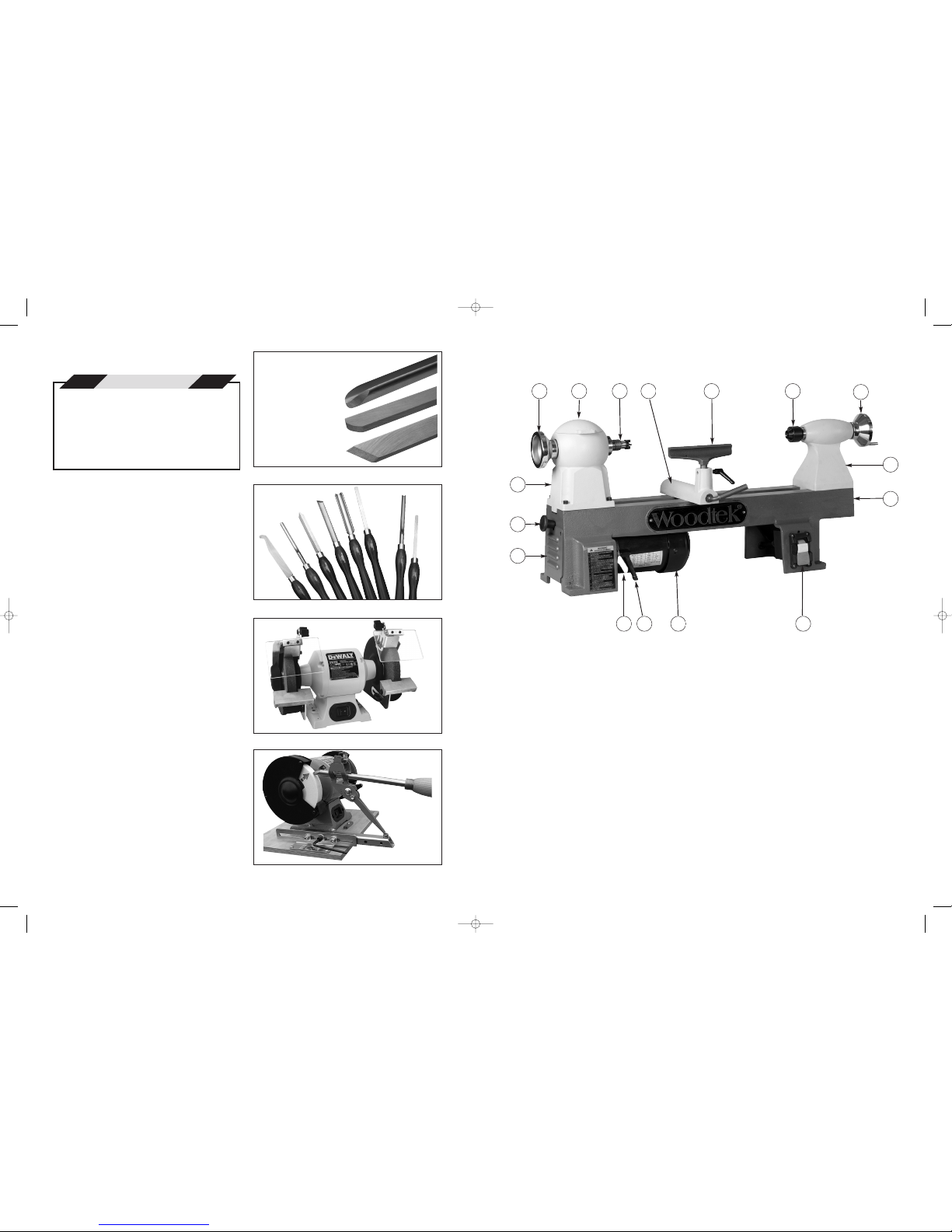
Basic Components . . . . . . . . . . . . . . . . . . . . . . . . . . . . . . . . . . . . . . . . . . . .7
Introduction
Overview . . . . . . . . . . . . . . . . . . . . . . . . . . . . . . . . . . . . . . . . . . . .8, 9
Headstock . . . . . . . . . . . . . . . . . . . . . . . . . . . . . . . . . . . . . . . . . . .8, 9
Pulley Drive . . . . . . . . . . . . . . . . . . . . . . . . . . . . . . . . . . . . . . . . . .8, 9
Tailstock and Tool Rest . . . . . . . . . . . . . . . . . . . . . . . . . . . . . . . . .8, 9
Operation
Turning Tools . . . . . . . . . . . . . . . . . . . . . . . . . . . . . . . . . . . . . . . . . .10
Sharpening . . . . . . . . . . . . . . . . . . . . . . . . . . . . . . . . . . . . . . . . . . .10
Spindle Turning . . . . . . . . . . . . . . . . . . . . . . . . . . . . . . . . . . . . . . . .11
Bowl Turning . . . . . . . . . . . . . . . . . . . . . . . . . . . . . . . . . . . . . . . . . .12
Troubleshooting . . . . . . . . . . . . . . . . . . . . . . . . . . . . . . . . . . . . . . . . . . . . . .13
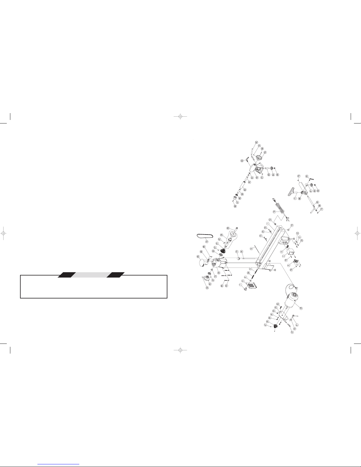
Parts Lists . . . . . . . . . . . . . . . . . . . . . . . . . . . . . . . . . . . . . . . . . . . . . . . . . .14
Schematic Drawing . . . . . . . . . . . . . . . . . . . . . . . . . . . . . . . . . . . . . . . . . . .15
REF REF REF
NO. PART NO. DESCRIPTION QTY NO. PART NO. DESCRIPTION QTY NO. PART NO. DESCRIPTION QTY
PARTS LIST
1 050763-000 LATHE BED 1
2 050764-000 SWITCH BOX 1
3 937335-000 ON/OFF SWITCH ASSY 1
4 020007-000 GROMMET, 6B3-2 2
5 380412-905 PIN 1
6 172019-000 MOTOR PULLEY COVER 1
7 250603-000 PULLEY COVER KNOB 1
8 006002-056 FLAT WASHER, 8.5x23x2t 1
9 000003-217 HEX CAP SCREW, 1
M8x1.25Px75
10 006002-040 FLAT WASHER, 8x30x3t 1
11 921457-000 MOTOR LOCKING HANDLE, 1
5/16"-18UNCx3/4"L
12 340063-615 GROMMET 1
13 021102-000 WIRE CLIP, ACC-2.5 2
14 250492-615 FOOT PAD 4
15 453011-028 POWER CORD, 1
SJT-18AWG-3C
16 380445-906 SHAFT LOCKING/KNOCKOUT 1
ROD
17 250372-615 KNOB 1
18 001102-208 ROUND HEAD TAPPING 2
SCREW, M4x1.59Px25
19 000302-109 ROUND HEAD SCREW, 2
M4x0.7Px16
20 000303-207 ROUND HEAD SCREW, 2
M5x0.8Px20
21 006502-200 STARWASHER, 2
5.3x10x0.6t(BW-5)
22 008004-200 HEX NUT, M5x0.8P 2
23 000302-205 ROUND HEAD SCREW, 2
M4x0.7Px15
24 008002-200 HEX NUT, M4x0.7P 2
25 171460-902 MOTOR TENSION PLATE 1
26 090116-000 MOTOR PULLEY 1
27 250495-625 HANDLE COVER 1
28 900540-000 MOTOR 1
29 003201-101 SET SCREW, 1/4x20UNCx1/4" 3
30 003001-106 HEX CAP SCREW, 2
1/4x20UNCx5/8"
31 006304-100 SPRING WASHER, 2
6.5x12.8x1.5t
32 003003-206 HEX CAP BOLT, 1
5/16x18UNCx1-1/4"
33 009105-200 LOCK NUT, 5/16"-18UNC 1
34 280117-901 SPRING 1
35 050761-000 HEADSTOCK 1
36 030408-000 BEARING, 6005-2HK 1
37 030407-000 BEARING, 6004-2HK 1
38 921604-000 SPINDLE SHAFT 1
39 921458-000 SPUR CENTER 1
40 240060-906 HEADSTOCK HANDWHEEL 1
41 090115-000 SPINDLE PULLEY 1
42 012003-009 KEY, 5x5x25 1
43 006304-100 SPRING WASHER, 4
6.5x12.8x2.0t
44 003103-104 SOCKET HEAD CAP SCREW, 4
1/4-20UNCx1-1/4"
45 921577-000 HINGE 1
46 050762-000 HEADSTOCK COVER 1
47 000203-102 SET SCREW, M6x1.0Px8 3
48 000401-201 FLAT HEAD SCREW, 4
M4x0.7Px8
49 050765-000 TAILSTOCK 1
50 360369-901 QUILL SCREW 1
51 010208-000 E-RING, ETW-12 1
52 360361-000 TAILSTOCK QUILL 1
53 921556-000 LOCKING HANDLE, 1
5/16"-18UNC-20L
54 921455-000 LOCKING HANDLE, 1
5/16"-18UNC-15L
55 380414-901 LIVE CENTER SHAFT, #2MT 1
56 030112-000 BEARING, 6002ZZ 1
57 380413-901 LIVE CENTER HEAD 1
58 380415-901 LIVE CENTER POINT 1
59 240053-906 TAILSTOCK HANDWHEEL 1
60 380444-906 HANDWHEEL HANDLE 1
61 010206-000 S-RING, ETW-9 1
62 380409-902 TAILSTOCK LOCKING HANDLE 1
63 380408-905 TAILSTOCK EYE BOLT 1
64 160053-901 LOCK PLATE 2
65 008312-200 LOCK NUT, M10x1.5P 2
66 050764-000 TOOL REST BASE 1
67 380411-902 TOOL REST EYE BOLT 1
68 380410-902 LOCKING SHAFT 1
69 160058-000 BUSHING 1
70 010003-000 S-RING, STW-12 2
71 070026-901 TOOL REST 1
72 014313-000 POLY-V BELT, 240J3 1
73 006711-100 WAVY WASHER, WW-20 1
74 570929-000 FACEPLATE, 3-1/8" DIA 1
75 383447-901 SPINDLE ADAPTER, 1
1"-8TPI TO 1-1/4"-8TPI
76 380443-906 SPUR CENTER POINT 1
77 940333-000 MANUAL 1
78 042607-000 GOGGLES 1
79 040005-00 ALLEN KEY, 5MM 1
80 004003-000 ALLEN KEY, 3MM 1
143-009 MidiLathe (16) 9/28/07 11:16 AM Page 3

13
4
1. Read and understand the entire Instruction
Manual before attempting assembly or
operation.
2. Maintain the original location and readability of
all warning labels.
3. Replace all worn or unreadable warning labels
from the manufacturer.
4. Read and understand all warnings posted on
this product.
5. Do not use this product for other than its
intended use.
6. Always wear approved safety glasses or face
shields while woodworking.
7. Wear ear protection during machine operations.
8. Always wear proper apparel without any loose
fitting material that may get caught in machinery.
9. Always keep hair tied back away from moving
machinery.
10. Provide adequate space around the work area
and use non-glare lighting.
11. Do not operate machinery while tired or while
under the influence of alcohol, drugs or any
medications.
12. Keep visitors and children a safe distance from
the work area.
13. Keep the workshop childproof by using padlocks
on master switches and removing starter keys.
14. Keep your work area well ventilated and use
proper air filtration systems and dust collectors.
15. Keep the floor around machinery clean and free
of dust, scrap material, oil and grease.
16. Make sure all machinery is properly grounded.
17. Make sure all machines are in the “off” position
before connecting to a power supply.
18. Do not lean on machinery and maintain a
balanced stance at all times.
19. Do not use excessive force to perform machine
operations. All machines are designed for
controlled operation.
20. Always work with undivided attention.
21. Always use the right tools at the correct speed
of operation.
22. Never leave a machine running and unattended.
23. Keep all cutting tools, blades and cutters sharp
for the best performance.
24. Unplug machinery from the power source before
making adjustments or for maintenance.
25. Make sure all guards are in place before
operation.
26. Repair any damaged machinery parts before
continuing operation.
27. Always turn machines off before cleaning.
28. Never stand on tools or use a machine for an
unintended use.
29. Use recommended accessories to support or
secure work pieces.
30. Always maintain tools in top condition for best
performance.
Additional Warnings and Safety Rules
1. Before starting the lathe, always ensure the
following: 1) the centers are free of dust and
debris, 2) the tailstock is securely locked down
to the lathe bed, 3) the tailstock center is tight
into the workpiece, 4) the tailstock quill locking
lever is tightened, 5) the tool rest levers are
tightened, 6) the indexing pin is disengaged.
2. Always check the condition of the workpiece
before starting the lathe. Do not turn work that is
out of balance, or work that has dangerous
knots, bark inclusions or poor glue joints.
3. Never drive the wood into the drive center while
in the headstock. This will damage the bearings.
4. Make sure the tool rest height is adjusted
properly.
5. Always keep the tool rest as close to the
workpiece as possible.
6. Never adjust the tool rest or tailstock while the
lathe is turning.
7. Ensure proper lubrication when using a cup or
dead center.
8. Always use the appropriate size faceplate.
9. Always fasten the workpiece securely to the
faceplate.
10. Always rough-cut the workpiece as closely as
possible to the finished shape and ensure
proper balance before turning.
11. Before starting, rotate work by hand first to
ensure clearance of all lathe components.
12. Always start the lathe with the speed turned off
and gradually increase to desired speed.
13. Never wear gloves while turning or sanding.
14. Always remove the tool rest when sanding.
15. Use slow speeds for rough work and higher
speeds for general cutting and finishing – see
speed recommendation chart.
16. Never grab the workpiece to slow it down while
the lathe is stopping.
WARNINGS
PROBLEM POSSIBLE CAUSE SOLUTION
TROUBLESHOOTING
No power
Excessive vibration
Motor overheats
Motor fails to develop power
Tools grab or dig into work
Tool chatters on workpiece
Cup center burns
Tool rest base creeps
1. Fuse blown or circuit breaker
2. Electric cord damaged
3. Defective belt
4. Defective motor
1. Workpiece out of balance
2. Defective bearings
3. Worn or defective belt
4. Defective motor
5. Bent pulley
1. Motor overloaded
2. Improper motor cooling
1. Motor not wired for correct
voltage
2. Supplied wires undersized
3. Low voltage
4. Low current
5. Defective motor
1. Tool rest set too far from work
2. Too aggressive of a cut
3. Improper tool use
1. Tool rest set too far from work
2. Improper tool for cut
3. Tool too dull
4. Bearings worn
1. Cup center improperly
lubricated
1. Tool rest base not tight
2. Too aggressive a cut
3. Heavy tool impacts from
unbalanced work
1. Replace fuse, reset breaker
2. Replace electric cord
3. Replace belt
4. Replace motor
1. Balance workpiece
2. Replace bearings
3. Replace belt
4. Replace motor
5. Replace pulley
1. Correct overload condition
2. Clean dust from motor
1. Wire motor correctly
2. Use correct sized wiring
3. Request voltage check
4. Correct low current condition
5. Replace motor
1. Position tool rest close to work
2. Moderate depth of cut
3. Use proper tool for type of cut
1. Position tool rest close to work
2. Use proper tool
3. Sharpen tool
4. Replace bearings
1. Lubricate cup center or use a
live center
1. Tighten tool rest base
2. Moderate depth of cut
3. Balance workpiece, use lighter
cuts
143-009 MidiLathe (16) 9/28/07 11:16 AM Page 4

5
12
SPECIFICATIONS
Motor . . . . . . . . . . . . . . . . . . . . . . . . . . . . . . . . . .1/2HP, 115VAC, 5A, 1720 RPM
Speeds (RPM) . . . . . . . . . . . . . . . . . . . . . . . . . .500, 840, 1240, 1800, 2630, 3975
Swing over bed . . . . . . . . . . . . . . . . . . . . . . . . . . . . . . . . . . . . . . . . . . . . . . . . . .10"
Swing over toolrest base . . . . . . . . . . . . . . . . . . . . . . . . . . . . . . . . . . . . . . . .7-1/4"
Distance between centers . . . . . . . . . . . . . . . . . . . . . . . . . . . . . . . . . . . . . . . . .17"
Inboard bed length . . . . . . . . . . . . . . . . . . . . . . . . . . . . . . . . . . . . . . . . . . . .23-5/8"
Bed gap . . . . . . . . . . . . . . . . . . . . . . . . . . . . . . . . . . . . . . . . . . . . . . . . . . . . .1-1/4"
Spindle size . . . . . . . . . . . . . . . . . . . . . . . . . . . . . . . . . . . . . . . . . . . . . . . .1" x 8TPI
Headstock taper . . . . . . . . . . . . . . . . . . . . . . . . . . . . . . . . . . . . . . . . . . . . . . .#2 MT
Headstock through bore . . . . . . . . . . . . . . . . . . . . . . . . . . . . . . . . . . . . . . . . . .3/8"
Faceplate diameter . . . . . . . . . . . . . . . . . . . . . . . . . . . . . . . . . . . . . . . . . . . . .3-1/8"
Tailstock quill travel . . . . . . . . . . . . . . . . . . . . . . . . . . . . . . . . . . . . . . . . . . . . .2-3/8"
Tailstock quill taper . . . . . . . . . . . . . . . . . . . . . . . . . . . . . . . . . . . . . . . . . . . .#2 MT
Tailstock through bore . . . . . . . . . . . . . . . . . . . . . . . . . . . . . . . . . . . . . . . . . . . .3/8"
Tool rest length . . . . . . . . . . . . . . . . . . . . . . . . . . . . . . . . . . . . . . . . . . . . . . . . . . .6"
Machine dimensions . . . . . . . . . . . . . . . . . . . . . . . .33-1/2"L x 9-1/2"W x 14-3/4"H
Net weight . . . . . . . . . . . . . . . . . . . . . . . . . . . . . . . . . . . . . . . . . . .87 lbs (39.5 kgs)
Shipping weight . . . . . . . . . . . . . . . . . . . . . . . . . . . . . . . . . . . . . .115 lbs (52.3 kgs)
Note: Specifications, while deemed accurate, are subject to change without notice.
DIAMETER ROUGHING GENERAL FINISHING
Under 1" 1800 2600 4000
1" to 3" 1200 1600 2600
3" to 6" 500 1200 1800
Over 6" 500 800 1200
SPEED RECOMMENDATIONS (RPM)
Some dusts created by woodworking activities may contain chemicals known to cause
cancer, birth defects, reproductive disease, respiratory disease and skin allergies.
Chemicals include: arsenic, chromium and formaldehyde from chemically treated
lumber and building materials; crystalline silica from masonry products; lead from
lead-based products; and quinones, alkaloids and glycosides from some exotic
hardwoods.
Warning
Preview
There are many different turning accessories used
for mounting wood on a lathe. This example covers
one procedure using a 3" faceplate and a 4-jawed
chuck with 1" x 8TPI spindle threads to fit this lathe.
Preparing the wood for turning
1- Wood selected for bowl turning can come from
many sources including trunks, branches, roots
and burls. Select a piece of fairly dry wood
about 5" in diameter and 3" deep.
2- Mark the center of the top of the bowl blank and
draw a circle with a compass the diameter of the
faceplate.
3- Center and screw the faceplate on the top of the
bowl and mount the turning blank on the inboard
spindle. The bottom of the bowl will be facing
outward.
Turning the bowl
1- With a 1/2" bowl gouge turned over on its side
and the flutes facing the direction of the cut, true
up the outside of the bowl at the speed
indicated on the Speed Chart.
2- Keep the bevel of the gouge running close to the
wood.
3- Remove the bulk of the waste wood from the
lower outside part of the bowl.
4- Define the outside shape of the bowl leaving
enough room on the bottom for a raised foot.
5- Turn a recess dovetail on the bottom of the bowl
to accept the internal chuck jaws.
6- Remove the bowl from the lathe and remove the
faceplate.
7- Put the chuck on the lathe and mount the
bottom of the bowl on the chuck.
8- Turn the inside of the bowl with a 1/2" bowl
gouge to a thickness of about 3/4". Start in the
middle of the bowl and turn away a small hollow.
9- Each successive cut should start further out
toward the rim and move down and into the
center of the bowl.
10- Continue in this manner until the bowl is
completely hollowed out with a wall thickness of
about 3/4".
11- Leave a raised center inside the bottom of the
bowl and cut a recess dovetail to accept internal
chuck jaws after seasoning.
12- Remove the bowl blank from the lathe and let it
dry. This may take several weeks or months
depending on how wet the wood is.
13- Once dried, remount the bowl using the dovetail
inside the bowl and true up the outside shape of
the bowl.
14- Turn a desired profile for the foot on the bottom
of the bowl and true up the bottom recess
dovetail.
15- Completely sand the outside of the bowl
including the foot and recess dovetail.
16- Remove the bowl from the lathe and remount
the bowl on the lathe using the bottom recess
dovetail.
17- Finish turning the inside of the bowl with long
shearing cuts from the rim to the bottom of the
bowl. As the wall thickness decreases use a
smaller 3/8" fingernail gouge for better control.
Keep the wall from vibrating by providing hand
support or using a bowl steady.
18- Completely sand the inside of the bowl. Finish
on or off the lathe as desired.
Bowl Turning
143-009 MidiLathe (16) 9/28/07 11:16 AM Page 5

11
6
INSTALLATION
Unpacking
The Woodtek Midi Lathe comes completely assembled in the packing crate. Prior to unpacking, make a
note of any damage to the packing crate. Immediately report any damage to the distributor where you
purchased the lathe. Carefully open the crate and inspect the lathe for any damage that may have occurred
during shipping. Immediately report any damage to the lathe to the distributor where you purchased the
lathe.
Cleaning
Locate the lathe where there will be sufficient working room around the lathe and ensure adequate
overhead lighting for all working positions around the lathe. Since airborne dust is a constant hazard with a
wood lathe, consideration should be given to lathe location relative to an exhaust system.
Location
Locate the lathe where there will be sufficient working room around the lathe and ensure adequate
overhead lighting for all working positions around the lathe. Since airborne dust is a constant hazard with a
wood lathe, consideration should be given to lathe location relative to an exhaust system.
Wiring
The Woodtek Midi Lathe comes wired for 115VAC operation. The electrical connection has a three-prong
grounded plug and should be plugged into a suitable three-prong, grounded outlet.
Do not modify the plug provided. If it will not fit the outlet, have the proper outlet installed by a qualified
electrician. Failure to have adequate grounding may result in the risk of electrical shock. Check with a
qualified electrician if you are not certain of proper receptacle grounding.
Preparing wood for turning
1- Wood selected for spindle turning should be
straight grained and free from knots and defects.
2- Mark the center point on both ends of the wood
with a center finder or similar marker and punch a
dimple with an awl or nail.
3- Drive the spur center into one end with a wooden
mallet. If the wood is very hard, cut perpendicular
kerfs through the center point with a bandsaw or
handsaw before setting the prongs into the wood.
Mounting the wood on the lathe
1- Put a live center or cup center into the tailstock. If
using a cup center, put a small dab of grease or
oil onto the end of the cup center.
2- Put the spur drive center into the headstock
spindle and align the prong marks in the wood
with the prongs in the spur center.
3- Bring the tailstock up to contact the center point
in the wood and tighten the tailstock.
4- Turn the tailstock quill handwheel until the wood is
tight between centers.
Roughing out the workpiece
1- Position the tool rest about 1/8" below the center
line of the spindle and about 1/8" away from he
workpiece.
2- Round the spindle with a roughing gouge ground
to a 30° angle moving back and forth with the
gouge slightly turned up on its side.
3- Never start from the end of a workpiece and
always work down hill from the wider to narrower
portion of the turning.
4- For the final cut, keep the indexing finger in the
curved notch in the tool rest and move the gouge
in one continuous motion along the length of the
tool rest.
Making beads and coves
1- Beads and coves are generally cut with a spindle
or detail gouge. Define the outside ends of the
bead by making a parting cut on either side to the
depth of the desired bead.
2- Roll and turn the gouge from the top center of the
bead down and in toward either side of the bead.
Cut with the tip of the gouge and make sure the
bevel of the gouge is flat against the bead. Make
repeated cuts until the desired bead is produced.
3- Define the ends of the cove by marking the
spindle with a pencil while the workpiece is
spinning.
4- Make the coving cut by rolling the gouge from the
side into the center of the cove. Move from side to
side keeping the dimension of the cove uniform.
Making parting and taper cuts
1- Parting cuts are made with narrow chisel or
diamond shaped parting tools. These cuts are
straight plunge cuts into wood to a selected
depth.
2- Taper and "V" cuts are usually made with a skew
chisel. Mark either side of the “V”. Keeping the
bevel of the skew parallel to the cut, make a
tapering cut by moving the point end of the skew
down and into the bottom of the taper.
Spindle Turning
143-009 MidiLathe (16) 9/28/07 11:16 AM Page 6

7
10
1. Lathe Bed
2. Tailstock
3. Tailstock Handwheel
4. Live Center
5. Tool Rest
6. Tool Rest Base
7. Spur Center
8. Headstock Cover
9. Headstock Handwheel
10. Headstock
11. Belt Access Cover Knob
12. Belt Access Cover
13. Motor Lifting Handle
14. Motor Locking Handle
15. Motor
16. On/Off Switch
BASIC COMPONENTS
10
9 8 7 6 5 4 3
1
1413
11
12
1615
2
Fig. 9
Fig. 11
Fig. 10
Fig. 12
Turning Tools
There are many types of turning tools on the market
today. The most common are High Speed Steel
turning tools. These can be organized into three
basic categories: gouges, scrapers and chisels
Fig 9. Gouges can be used for a variety of cuts
from roughing out spindles to cutting out deep
hollows in bowls. Scrapers are commonly used for
general cutting purposes where a harder edge is
required or for finishing at very high speeds. Chisels
have sharp pointed edges and are very effective in
shear cutting and fine detail work but will dull more
quickly than scrapers. A selection of good quality
turning tools makes wood turning safer and more
enjoyable and should include tools from all
categories Fig 10.
Sharpening
Turning tools are commonly sharpened using a
bench grinder but are also sharpened with sanders
and hand held stones and honing pads. An 8"
bench grinder with a coarse and fine wheel
mounted on either side of the grinder is a common
bench grinder setup for woodturning Fig 11. Turning
tools can be supported by hand on adjustable
platforms or mounted into a grinding jig for
sharpening Fig 12. Grinder speed is a matter of
preference but 1750 RPM is the average speed
generally used for woodturning tools. Knowledge of
sharpening techniques will result in more effective
sharpening.
OPERATION
Many books, videos and workshops are
available on the subject of woodturning.
Before turning on this lathe, prior
experience in woodturning is
recommended. The information below is
presented as a brief overview of basic
woodturning procedures.
Caution
Gouges
Scrapers
Chisels
Turning Tools
143-009 MidiLathe (16) 9/28/07 11:16 AM Page 7

9
8
INTRODUCTION
Overview
The Woodtek Midi Lathe is a heavy duty cast iron midi lathe designed for turning small bowls, spindles,
pens and miniature turnings. It has a 10" swing with 7-1/4" over the tool rest base and 17" between centers.
The lathe is powered by 1/2HP, 115VAC motor with six pulley speeds: 500, 840, 1240, 1800, 2630 and 3975
RPM. The lathe comes with a 4-prong spur center, ball bearing live center, 3-1/8" faceplate, 1" -8TPI to 1-
1/4" -8TPI spindle adapter and a spindle shaft rod.
Headstock
The headstock spindle has standard 1" - 8TPI spindle threads with a #2 Morse taper. It will accept a range
of standard accessories. The spindle shaft has a 3/8” through-bore for removing drive centers. To remove
the drive center from the spindle shaft, slide the spindle shaft rod through the spindle shaft until it contacts
the heel of the drive center and then drive it out with a mallet Fig.1. To lock the spindle shaft for attaching or
removing faceplates or chucks, insert the spindle shaft rod into the hole in the side of the spindle shaft and
rotate it until it rests against the side of the lathe bed Fig. 2. Then attach or remove the faceplate or jawed
chuck with a suitable tool.
Pulley Drive
Speeds can be quickly changed on the Woodtek Midi Lathe. First ensure that the lathe is turned off and the
unit is unplugged. Open the headstock cover and then open the belt access cover on the rear of the
headstock by pulling the knob out and up and lowering the cover plate Fig. 3. Loosen the motor locking
handle and lift the motor all the way with the motor lifting handle and then tighten the motor locking handle
Fig. 4. Move the belt to the desired pulley location on the headstock pulley and the corresponding motor
pulley Figs. 5 and 6. Unlock the motor locking handle, lower the motor and tighten the handle. Close the
headstock and belt access covers and plug in the lathe.
Tailstock and Tool Rest
The tailstock quill shaft has 2-3/8" of travel, a #2 Morse taper and a 3/8" through-bore. To remove a center
from the quill, turn the tailstock handwheel counter-clockwise all the way until the center self-ejects Fig. 7.
Short tapered centers will need to be removed with the spindle shaft rod inserted through the quill through-
bore and knocked out with a mallet as in figure 1. The locking positions of the tailstock and tool rest locking
handles are factory set but if they need to be adjusted, lightly turn the locking nut under the bottom locking
plate to adjust the handle position Fig. 8.
Fig. 1
Fig. 3
Belt access cover plate
Fig. 5
Fig. 7
Fig. 2
Spindle
shaft rod
Fig. 4
Motor lifting handle
Fig. 6
Fig. 8
Motor locking handle
143-009 MidiLathe (16) 9/28/07 11:16 AM Page 8
Table of contents