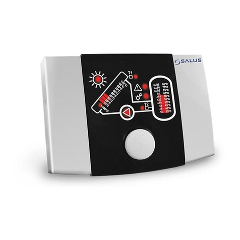
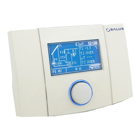
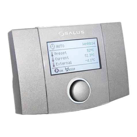
Salus PCSol 201 User manual

INSTALLATION AND OPERATION MANUAL
REVISION: 1.1_EN
Controller
PCSol 201
FOR SOLAR COLLECTORS
07-2020


3
CONTENTS
1. SAFE INSTALLATION AND USE 4
2. GENERAL 5
3. DIRECTIVE WEEE 2012/19/UE 5
4. DOCUMENT KEEPING 5
OPERATING MANUAL 7
5. OPERATION 8
6. CONTROLLER MENU 8
7. SETTINGS MENU 10
8. TIME PROGRAMS 10
8.1.
TDHWMIN ...........................................................................10
8.2.
ROOM TEMPERATURE........................................................11
8.3.
CIRCULATION ......................................................................11
9. MENU ALARMS 11
10. OPTIONS MENU 13
10.1.
RESTORING FACTORY SETTINGS ........................................13
10.2.
READING DEFAULT SETTINGS ............................................13
10.3.
CLEARING HEAT OUTPUT DATA .........................................13
11. OPERATION MANU 13
11.1.
OPERATION\SETTINGS MENU............................................13
11.2.
OPERATION\LOUDNESS MENU..........................................14
11.3.
OPERATION\CLOCK MENU .................................................14
12. HEAT OUTPUT 15
13. SOLAR APPLICATIONS 16
13.1.
NIGHT COOLING..................................................................16
13.2.
SOLAR THERMAL SCHEME A ..............................................16
13.3.
SOLAR THERMAL SCHEME B ..............................................17
13.4.
SOLAR THERMAL SCHEME C ..............................................17
13.5.
SOLAR THERMAL SCHEME D ..............................................18
13.6.
SOLAR THERMAL SCHEME E...............................................19
13.7.
SOLAR THERMAL SCHEME F...............................................19
13.8.
SOLAR THERMAL SCHEME G ..............................................20
13.9.
SOLAR THERMAL SCHEME H ..............................................21
13.10.
SOLAR THERMAL SCHEME I .....................................21
13.11.
SOLAR THERMAL SCHEME J.....................................22
13.12.
SOLAR THERMAL SCHEME K ....................................23
13.13.
SOLAR THERMAL SCHEME L ....................................23
13.14.
SOLAR THERMAL SCHEME M...................................24
13.15.
SOLAR THERMAL SCHEME N ...................................25
13.16.
SOLAR THERMAL SCHEME O ...................................25
14. SHUT DOWN 26
15. TECHNICAL DATA 28
16. INSTALLATION 28
16.1.
INSTALLATION OF THE CONTROLLER ................................28
16.2.
EXTERNAL CIRCUITS CONNECTION....................................30
16.2.1.
Use of connectors .....................................................30
16.2.2.
Power supply connection .........................................31
16.2.3.
Connecting the PWM signal of the solar pump ......31
16.2.4.
Temperature sensor connection .............................31
16.2.5.
Temperature sensor installation..............................32
16.2.6.
Room temperature sensor installation ...................32
16.2.7.
Output H connection ................................................33
17. APPLICATION SCHEMES 34
17.1.
SOLAR APPLICATION SCHEME A ........................................34
17.2.
SOLAR APPLICATION SCHEME B ........................................35
17.3.
SOLAR APPLICATION SCHEME C ........................................36
17.4.
SOLAR APPLICATION SCHEME D ........................................37
17.5.
SOLAR APPLICATION SCHEME E.........................................38
17.6.
SOLAR APPLICATION SCHEME F.........................................39
17.7.
SOLAR APPLICATION SCHEME G ........................................40
17.8.
SOLAR APPLICATION SCHEME H ........................................41
17.9.
SOLAR APPLICATION SCHEME I..........................................42
17.10.
SOLAR APPLICATION SCHEME J...............................43
17.11.
SOLAR APPLICATION SCHEME K ..............................44
17.12.
APLIKACJA SCHEMAT SOLARNY L ............................45
17.13.
SOLAR APPLICATION SCHEME M.............................46
17.14.
SOLAR APPLICATION SCHEME N .............................47
17.15.
SOLAR APPLICATION SCHEME O .............................48
18. CASING CLOSING 49
19. CONTROLLER OPTIONS 49
19.1.
SYSTEM OPTIONS\SETTINGS ..............................................50
19.2.
I\O OPTIONS\CONFIGURATION .........................................51
19.2.1.
Wire length compensation .......................................51
19.3.
OPTIONS\FUNCTIONS.........................................................51
19.3.1.
Vacuum collector function .......................................52
19.4.
MANUAL MODE ..................................................................52
19.5.
SCHEME WIZARD ................................................................53
20. FUSE REPLACEMENT 53

4
1. SAFE INSTALLATION AND USE
The controller is designed only for household
and similar use.
Before installation, service or maintenance
and prior to making any connections, always
disconnect power supply and make sure that the
terminals and electric wires are not energized.
When the controller is switched off using
keyboard or encoder, the controller
terminals are still under dangerous
voltage.
Controller may be used only for its
intended purpose.
It is required to use auxiliary protection
automatics to protect hot water system,
CH system (if any) in case of the
controller or software malfunction
Programmable settings must be selected
suitably to your system type, taking into
account all of its operating conditions.
Wrongful settings may cause the collector
or reservoir malfunction (e.g. collector
overheating, etc.).
Programmed settings may be modified
only by a person who read and
understood this manual.
Use only in heating systems that are set
up in accordance with valid regulations.
Electric system to which the controller is
connected must be protected with a cut-
out device suitable for expected loads.
Never use the controller when its casing
is damaged.
In any case do not alter the controller
components.
The controller has electronic
disconnection for connected devices
(operation 2.B according to PN-EN
60730-1). It means that at 230V voltage
supply the pump outlets have dangerous
voltage, even if the pumps are not
controlled.
Do not allow children access to the
controller.
Before you open casing, first disconnect
power supply from the unit.
The controller must be installed in
accordance with the requirements of EN
60335-1 standard, by qualified and
authorized technician.
Do not install the unit when it is
connected to voltage.
Short circuit in pump output will damage
your unit.
Do not operate the unit when it is
malfunctioning or was repaired by
unauthorized persons.
Do not mount the unit on flammable
materials.

5
2. GENERAL
Controller PCSol201 is an advanced electronic
unit designed for distribution of heat from solar
collectors. Works with solar pumps HIGH
EFFICIENCY controlled signal PWM. The controller
is used to control solar circuit systems
accordingly to indications from temperature
sensors to recover highest possible energy from
the collector.
Fig. 2.1 Basic functional diagram
3. DIRECTIVE WEEE 2012/19/UE
Purchased product is designed and made of
materials of highest quality.
The product meets the requirements of the
Directive 2012/19/EU of 4 July 2012 on
waste electrical and electronic equipment
(WEEE), according to which it is marked by the
symbol of crossed-out wheeled bin (like below),
meaning that product is subjected to separate
collection.
Responsibilities after finishing a period of using
product:
dispose of the packaging and product at the
end of their period of use in an appropriate
recycling facility,
do not dispose of the product with other
unsorted waste,
do not burn the product.
By adhering obligations of waste electrical
and electronic equipment controlled disposal
mentioned above, you avoid harmful effects on
the environment and human health.
4. DOCUMENT KEEPING
Please, keep carefully this installation and
operating manual and any other relevant
documents, so that they may be used at any
time. In case when you move or sell the unit,
please give the attached documents to its new
user.
PCSol201


OPERATING MANUAL
PCSol 201

8
3sek.
5. OPERATION
The controller has
TOUCH&PLAY system
that facilitates its
operation. Encoder is
operated by its rotating
and pressing.
To start the controller,
keep pressed encoder
knob for 3 seconds.
Welcome screen will be
displayed:
Fig. 5.1 Welcome screen *
* starting screen may differ depending on controller
version.
After the welcome screen the controller displays
the main screen.
Fig. 5.2 Main screen
Controller outlets operation is each time indicated
by their blinking on displayed diagram.
6. CONTROLLER MENU
Any time during controller
operation, when you keep the
encoder pressed for 3 seconds. it
will cause exit to the main screen.
All controller settings are made
through menu system. MENU is
recalled by pressing encoder on
main screen to select icon.
Fig. 6.1 Recalling controller’s menu
When MENU is open, the unit will display a
screen with icons that represent the controller
functions:
Fig. 6.2 Controller menu
In middle on the screen you can see active item
icon selected as in Fig. 6.2. Now, you may turn
encoder knob to move through menu items. In
main MENU there will be:
Fig. 6.3 Main menu items
Where: Icon TDHWmin (second one) is shown only, if active
scheme is B and J.
Note: The function of this icon changes to Room temp. when
the active scheme is the Mscheme. Circulation icon (third
one) when active scheme will be B,C,D,E,G,H,J,K,L,O.
Circulation icon (third one), if active scheme is B, C, D, E, G,
H, J, K, L, O.
PCSol 201

9
Values of settings are edited in scrollable
submenu. Example for submenu preset is shown
below. To edit setting value select required
setting and press the knob; the value will start
blinking. Now, rotate the knob to change the
setting value. The changed value will be
confirmed, when you press the knob again, and
you may select other setting.
After edition in submenu you may select
the following by pressing on selection:
OK Confirms changes and exits to menu; it
allows reverse reaction to encoder turning;
CANCEL Rejects changes in entire
submenu and exits to menu.
Fig. 6.4 Scrollable submenu
Fig. 6.5 Controller’s menu structure
only scheme
A, B, C, E, F, H, I, J, L, M, N, O
only scheme
B, C, D, E, G, H, J, K, L, M, O
only scheme B, M
Note: for M the icon has a different function

10
7. SETTINGS MENU
Access
This menu is used to make basic settings of
the controller. Change of parameters is only
accepted when you use OK in left lower corner of
the screen. Use CANCEL to reject any made
changes. List of parameters in this menu
depends on selected solar scheme. Parameters
are described in details in section 13 about
particular solar applications.
Depending on scheme and version of unit,
the following parameters are available in Settings
menu:
Parameter
Scheme
A
B
C
D
E
F
G
H
I
J
K
L
M
N
O
TsDHW
X
X
X
X
X
X
X
X
X
X
X
X
X
X
TsDHWmi
n heater*
X
dTAB
X
X
X
dTCO
X
X
Eco mode
X
Night
cooling
X
X
X
X
X
X
X
X
X
X
X
Night
cooling ON
X
X
X
X
X
X
X
X
X
X
X
Night
cooling
OFF
X
X
X
X
X
X
X
X
X
X
X
TsPOOL
X
X
X
Priority
X
X
Alarm
TCOLcr
X
X
X
X
X
X
X
X
X
X
X
X
X
X
X
* parameter available only for M scheme.
8. TIME PROGRAMS
For correct operation of time programs
it is required to set the clock.
8.1.TDHWmin
Access
Item available only in B scheme. Note:
The icon changes its destination after
selecting the M scheme.
Time program TDHWmin is minimal
temperature of DHT reservoir (T3 sensor), below
which the controller controls H output (heater or
other additional heat source).
When you switch off the temperature value in
value edition box,the time program will be set
off and the controller will use stable value for
TDHWmin parameter (single temperature value
all the time), during edition it may be seen that
the temperature has the same value all along the
diagram.
Fig. 8.1 Edition of TDHWmin value
To set the TDHWmin to change in time, it
is required to set schedule. It is done by setting
sch. value in value edition box.
Fig. 8.2 Activating time program for TDHWmin
When sch. value is confirmed, new item
MO-FR will be displayed; edit this value to select
one of the three time ranges:
MO-FR –time program for days Monday to
Friday,
SAT. –time program for Saturday,
SUN. –time program for Sunday.
After you confirmed desired time range,
use the knob to move the position marker to the
place (hour range), for which you want to edit
value.
Fig. 8.3 Setting marker position
Here, press the knob to hide the position
marker and to light the edition marker. When the
edition marker is lit, turn the knob to change
temperature value for current position marker.

11
Fig. 8.4 Setting edition marker
When you set temperature and pressed
the knob, both edition marker and position
marker will be displayed on the screen, and you
may turn the knob to copy the value to adjacent
positions. Press again the knob to move to the
position marker.
Fig. 8.5 Setting value movement
Select OK and press the knob, while in position
marker mode, to confirm changes made in
schedules. Activate CANCEL to exit without
saving changes in schedules.
8.2.Room temperature
Access
The position changes its destiny only in
scheme M.
Time program Room temp. is the
temperature set by the CT7 room temperature
sensor below which the sensor will influence on
the controller that will control the CH pump.
When switch off the temperature value in
value edition box,the time program will be set
off and the influence of the room thermostat on
the regulator, and the controller will use stable
value for Room temp. parameter (single
temperature value all the time). During edition it
may be seen that the temperature has the same
value all along the diagram.
Changes in time programs for Room temp. is
done in the same way as shown in the example
of scheduling settings TCWUmin.
8.3.Circulation
Access
Item available only in schemes B, C, D, E,
G, H, J, K, L, M, O.
Changes in circulation time programs are
introduced the same like it was demonstrated for
TDHWmin schedule settings.
Fig. 8.6 Menu structure
Possible settings in value edit box are
YES, NO AND sch. Value YES will enable
constant circulation. Value NO will disable
circulation. Value sch. will activate time program
for circulation.
9. MENU ALARMS
Access
The controller may alarm on any
irregularities in operation.
The controller has an intelligent alarm
function. It means that the controller recognizes
type of alarm condition and takes respective
remedy actions accordingly to the conditions. For
instance, if the sensor of reservoir extra heating
with a heater fails, the controller prevents extra
heating for the reservoir. Despite of alarm, the
solar circuit will continue correct operation and
the controller will not let the reservoir to be
overheated.
Type of action taken by the smart alarm
depends on the alarm type and on the solar
application.
When in the main screen in the screen
bottom ALARM! sign starts blinking (Fig. 5.2), it
means alarm situation. Now, entering through
Edition marker
Current marker
hour range
Current marker
value
sch.
MON-FRI

12
menu to Alarms we have access to contents and
code number of alarm reported by the
controller (Fig. below).
Fig. 9.1 Alarm screen
If the shown item number is higher than
1, it means multiple alarms, to be seen by
turning the knob.
Lower left corner indicates the alarm code.
Alarm codes are summarized in the table below,
to facilitate their identifications and remedies:
List of alarms
No.
Alarm
1
DHW reservoir overheating
Maximal DHW reservoir temperature has been
reached (exceeded temperature specified as
TDHWmax). Pump that loads heat to reservoir
is stopped. This alarm has higher priority than
collector alarms (if collector temperature alarms
occur at the same time, solar pump will not be
started whatsoever). It is required to cool
reservoir, e.g. by discharging hot water.
2
Solar panel overheating
P1 stop
Collector pump will be stopped by the time,
when collector temperature drops below
TCOLmax. It is possible to start pump in
manual service mode. Check work fluid flow
(possible air in system or collector pump is not
controlled).
This alarm may be due to exceeded reservoir
temperature alarm (Code 1).
3
Solar panel critical temperature
It means that collector critical temperature has
been reached (parameter TCOLcr) and despite
reaching temperatures (TsDHW, TsPOOL)
collector pump will be started, until collector
temperature drops below TCOLcr. Wait for
collector cool down. If menu option “Alarm
TCOLcr” is set as NO, controller will not report
this alarm, but it will take described actions.
4
T1 sensor malfunction
Alarm informs on incorrect operation or damage
to T1 sensor. Check connections for continuity
(connect) or short circuit (eliminate) in sensor
circuit. Alarm will stop collector pump, algorithm
stops DHW reservoir loading.
5
T2 sensor malfunction
Alarm informs on incorrect operation or damage
to T2 sensor. Check connections for continuity
(connect) or short circuit (eliminate) in sensor
circuit. Alarm will stop collector pump, algorithm
stops DHW reservoir loading.
6
T3 sensor malfunction
Alarm informs on incorrect operation or damage
to T3 sensor. Check connections for continuity
(connect) or short circuit (eliminate) in sensor
circuit. This alarm depends on solar thermal
scheme. At Bscheme (with heater) extra
heating of reservoir will be stopped (output H is
off) and alarm is not reported. In schemes A, C
sensor has informative function and controller
will not report any alarms from these sensors.
7
T4 sensor malfunction
Alarm informs on incorrect operation or damage
to T4 sensor. Check connections for continuity
(connect) or short circuit (eliminate) in sensor
circuit. This alarm depends on Solar thermal
scheme. Alarm is reported only at schemes D, G
or K, where operational algorithm requires this
sensor. At other schemes (B, C, E, F, H, I*) T4
sensor is used to calculate heat output and its
malfunction is not reported, while heat output is
not calculated.
*T4 sensor operation in I scheme depends on dTP2
parameter, as described in section 19.1
8
DHW A reservoir overheating
An alarm informing that the TDHWmax defined
maximum temperature of DHW A (A buffer in
K scheme) has been reached. A pump loading
heat into this container/buffer will be halted.
Container/buffer should be cooled down, e.g. by
letting warm water our and/or disconnecting
alternative heat source from the container.
9
DHW B reservoir overheating
Alarm on reaching maximal temperature defined
in TDHWmax parameter in DHW B reservoir.
Pump that loads heat to this reservoir will be
stopped. Cool down this reservoir, e.g. by hot
water discharge.
10
Solar panel A critical temperature
In system with two collectors (only Solar
thermal scheme H) alarm on exceeding critical
temperature (parameter TCOLcr) in A collector.
Controller, despite that preset temperature
TsDHW is reached, will start collector pump P1
in order to lower temperature below critical.
Wait for collector cool down. If menu option
“Alarm TCOLcr” is set as NO, controller will not
report this alarm, but it will take described
actions.
11
Solar panel B critical temperature
In system with two collectors (only Solar
thermal scheme H) alarm on exceeding critical
temperature (parameter TCOLcr) in B collector.
Controller, despite that preset temperature

13
TsDHW is reached, will start collector pump P2
in order to lower temperature below critical.
Wait for collector cool down. If menu option
“Alarm TCOLcr” is set as NO, controller will not
report this alarm, but it will take described
actions.
12
Solar panel A overheating. P1 stop
Acircuit collector pump (at scheme H) will be
stopped, until collector temperature drops below
TCOLmax. It is possible to start pump in
manual service mode.
13
Solar panel B overheating. P2 stop
Bcircuit collector pump (at scheme H) will be
stopped, until collector temperature drops below
TCOLmax. It is possible to start pump in
manual service mode.
14
Antifreeze STOP
During antifreeze performance collector pump is
started to increase temperature of too cold solar
work fluid. Energy from reservoir or pool will be
used for this purpose. However, if reservoir or
pool temperature is near 2°C, controller will stop
antifreeze function to prevent heat source
damage and will initiate alarm. Antifreeze
function is wider described in section
Options\Functions 19.3.
10. OPTIONS MENU
Access
You must log-in to enter the options. Login
screen is presented in Fig. 10.1
Fig. 10.1 User login screen
Access to this menu is protected with
password. This menu settings are used by
installer/servicer. Detailed description of the
options parameters is included in installation part
of the manual.
Password 0000 will display submenu
parameters only for reading.
10.1. Restoring factory settings
This menu allows restoring factory
parameters and settings. In login screen enter
password 0002 and confirm to restore only
default user settings. Service parameters will not
be changed. After restoration of factory settings,
parameters available in Options menu will not be
changed.
Before restoration the controller will show a
request to confirm this action.
After restoring factory settings you must set
the clock, as it has been reset to date: 00:00,
01-01-2010.
10.2. Reading default settings
The controller has default settings table (that
will be restored). Default settings may be read by
entering password 0005 in login screen. The
table is only for reading type and it may not be
edited.
10.3. Clearing heat output data
Password 0003 will clear any heat output
chart in the controller.
Password 0004 will clear heat output
counter.
After entering passwords 0003 and 0004
the controller will display request for
confirmation. Select “NO” to exit without
changes.
List of codes
0000
Table of option submenu settings only
for reading
0002
Restores default settings of User group
(not protected with password)
0003
Clears heat output chart
0004
Clears heat output counter
0005
Default settings table
Access to Options submenu
Restores default settings in groups
User and Service in controller (all
parameters)
11. OPERATION MANU
This menu is dedicated to the user. Here, you
may change basic settings of the controller only
operation.
11.1. Operation\Settings Menu
Access
This menu allows the user to access:
Nameplate –It has three pages. Navigate
between pages by turning the knob left/right.
First page (1/3) allows you to read
information on the unit hardware and
software version;

14
Fig. 11.1 2 Page (1/3) of Nameplate
Page (2/3) includes manufacturer’s contact
details.
Fig. 11.3 Page (2/3) of Nameplate
Page (3/3) includes information on
microcontroller and software compilation;
Language –allows changing language of
descriptions. You may select the following:
PL-Polish,
EN-English, IT-Italian, ES-Spanish,
DA-Danish, RO-Romanian, EL-Greek,
FR-French, CS-Czech, RU-Russian,
DE-German;
Encoder direction –reverts reaction for
encoder turning;
Time Out –inactivity time, in seconds, after
which the unit automatically exits menu and
the screen and knob illumination go off;
Menu speed –adjusts fastness of menu
animations;
Ambient light –sets illumination pulsating after
the display turned off (when Time Out has
elapsed). This function is useful to find the
controller in dark rooms. Encoder knob light
pulsation will be also performed after the
controller is switched off.
11.2. Operation\Loudness Menu
This many includes sound settings. Turn encoder
to move between sound settings and controller’s
message sounds on and off.
Fig. 11.4 Sound settings screen.
When sounds are switched off, the knob
turning will not be confirmed by acoustic signals.
Switching alarm sounds on will cause that
alarm events are reported together with sound
signal. If this option is unchecked, any alarm
messages will be silent: only display blinking.
Alarms will not be confirmed by sound signal.
11.3. Operation\Clock Menu
Access
For correct operation of time programs the
unit uses real-time clock, which must be set
before the controller start working.
Not set or wrongly set clock will cause
incorrect operation of time programs
and night cooling function
Day of week as seen in main window will
be calculated automatically.
Fig. 11.5 Clock setting screen
PCSol 201
About
OK

15
Date and time setting must be confirmed
with “OK”. When you select “CANCEL”, any
changes will be rejected.
The controller has function of sustaining
clock for 10 days. After this time, if power supply
is not restored, the clock will reset.
12. HEAT OUTPUT
Access
The controller counts energy recovered from the
collector. Heat output visualization differs
depending on the controller version.
Heat output function is not available in
solar thermal schemes D, G and K.
Calculation of heat output and
momentary power requires additional
temperature sensor CT6 connected to
measurement input T4. If the sensor is
not connected, heat output will not be
counted.
In solar applications that for their
operation require four temperature sensors, heat
output counting is not possible. These
applications are D and G. When the schemes are
on, the controller menu will not display heat
output icon and the function may not be entered.
The controller logs data on recovered
energy from last 14 days in the form of bar
chart.
Fig. 12.1 Heat output screen
Energy total counter is displayed at the
bottom of the screen. It counts energy recovered
from the solar panel from the beginning of the
unit’s lifetime. The counter data are stored in
non-volatile memory that is not affected by
power losses.
First bar in the chart stands for energy
recovered on current day and it is updated every
full hour.
At midnight, the controller will move data
one position to the right and start counting for
new current day.
It is possible to turn the heat output chart
on in the main screen (in place where active
Solar thermal scheme is displayed). In the main
screen, the controller displays data for 7 days.
Fig. 12.2 Heat output in main screen
Data are updated every full hour and the
entire chart is moved at midnight. To see data
for previous days, you must enter the heat
output menu.
Fig. 12.3 Heat output in main screen

16
13. SOLAR APPLICATIONS
13.1. Night cooling
Due to the fact that in solar thermal
schemes C, F, Ithere is no risk of
reservoir overheating and that other
protection means are provided for them
against overheating, the function of night
cooling is not available in these schemes.
For correct operation of night cooling it is
required that the clock is set.
Night cooling function is used to cool
DHW reservoir by emitting excess heat through
cold collector. It is done by starting the collector
pump.
During night cooling, any alternative
sources of energy will be switched off.
There are three settings for night cooling
function: Night cooling, Night cooling ON,
Night cooling OFF and they are in “Adjustment”
menu.
Night cooling- YES: switches on, NO: switches
off the night cooling mode. When the mode
is on, the controller, in hours 000÷500, if T2
sensor temperature is higher than specified
in Night cooling ON setting; will decide to
start night cooling. The controller will start
the collector pump in order to discharge to
reservoir and will be cooling the reservoir to
reach temperature specified in Night
cooling OFF setting. In this mode, the
controller additionally monitors the collector
temperature; cooling will be stopped for
some time, if T1+dToff>T2. Regardless
prior conditions, the controller will exit from
the cooling mode at 500 and return to normal
operation. Activation of night cooling mode is
indicated in the screen as blinking moon icon
near the collector picture.
Night cooling ON - DHW reservoir temperature
(measured by T2), when reached, if night
cooling function is enabled (prior item)
000÷500 and the temperature at T2 sensor is
higher than Night cooling ON temperature,
the controller will decide on night cooling
activation. The controller will start the
collector pump to discharge the reservoir and
it will continue to cool the reservoir to the
temperature set for Night cooling OFF.
Night cooling OFF - DHW reservoir
temperature (T2 sensor), to which the
controller will be cooling the reservoir during
night cooling function. When the temperature
drops to the one specified for Night cooling
OFF,the controller will stop night cooling.
Additionally, depending on selected scheme,
the controller will control additional outputs, so
as to discharge heat more efficiently.
In scheme B during night cooling, circulation on
output P2 will be activated (regardless any time
programs etc.); heater operation will stopped
(output H is turned off, regardless any time
programs etc.).
In schemes D, E, G, J, K, L, M during night
cooling, circulation on output H will be activated
(regardless any time programs etc.).
13.2. Solar thermal scheme A
Loading of DHW reservoir with solar collector.
This basic solar application.
Fig. 13.1 Solar thermal scheme A
The collector pump will be started with
100% capacity, when difference between T1 and
T2 exceeds value of dTonDHW
setting and it will be working for the time
specified in tP setting. If upon this time the
difference between T1 and T2 is still above
dTonDHW, the pump speed will remain at
100%. If the temperature difference between T1
and T2 drops below dTonDHW, the controller
will start reducing the pump speed, until the
moment when T1
and T2 difference reaches value specified in
dToffDHW setting. When T1 and T2 difference
is between the values dTonDHW ÷ dToffDHW,
the controller will calculate and set the pump
speed proportionally. When dToffDHW is
reached, the pump will work at minimal speed
(parameter Pmin), below it will be stopped.
System will work by the time when T2
sensor preset temperature TsDHW is reached,
than the collector pump P1 is stopped.
If the collector temperature T1 reaches
critical value (TCOLcr parameter), the controller
will allow the collector pump to be switched on to
lower the collector temperature below HP1
hysteresis parameter.
If the reservoir temperature on T2 sensor
reaches the value of TDHWmax, than the
controller, despite critical collector’s temperature
(TCOLcr), will stop the collector pump, disabling
the collector cooling. It is to protect the reservoir
from overheating.

17
List of settings in Adjustment menu
TsDHW- Reservoir temperature preset.
Night cooling- YES enables / NO disables night
cooling in hours 000÷500.
Night cooling ON –DHW reservoir temperature
(T2 sensor), if exceeded at 000, if night
cooling function is enabled, the controller will
decide on night cooling activation.
Night cooling OFF –DHW reservoir
temperature (T2 sensor), to which the
controller will cool the reservoir (if night
cooling is enabled and in hours 000÷500
Night cooling ON temperature is
exceeded).
Alarm TCOLcr –Switching on (YES) or off (NO)
the alarm on exceeding TCOLcr
temperature. This function does not affect
the controller’s operation. If the setting is set
as NO, the controller will not report any
alarm after TCOLcr temperature has been
exceeded on the collector’s sensor.
13.3. Solar thermal scheme B
Loading of DHW reservoir with a function of
extra heating by the use of a heater
Fig. 13.2 Solar thermal scheme B
The collector pump will be started with
100% capacity, if the difference between T1 and
T2 exceeds value of dTonDHW
setting and it will work for the time as specified
in tP. If after this time the difference between T1
and T2 is still above dTonDHW,
the pump speed will remain at 100%. If the said
difference T1 and T2 drops below dTonDHW,
the controller will start reducing the pump speed,
until the difference between T1
and T2 reaches the value specified as
dToffDHW. When the difference between T1 and
T2 is between the values dTonDHW ÷
dToffDHW, the controller will calculate and set
pump speed proportionally. If dToffDHW is
reached, the pump will work at minimal speed
(parameter Pmin), below it will be stopped.
The controller will heat up CWU reservoir
using a heater or other heat source (H output)
up to the temperature of TDHWmin. Functioning
of Houtput depends also on eco function set up,
as described in „Adjustment” menu.
TDHWmin temperature is set through
main menu item TDHWmin.
List of settings in Adjustment menu:
TsDHW- Reservoir temperature preset.
Eco mode- economic mode on or off (power
saving) YES Extra heating of DHW reservoir
with a heater or other source of heat (H
output) to the temperature of TDHWmin,
when the collector is not working (P1 pump
stops due to poor sunlight).
When the collector pumpis started, the
controller will turn the heater off (H output).
NO Extra heating of DHW reservoir with a
heater or other source of heat (H output) up
to the temperature of TDHWmin, regardless
if the collector supplies energy or not.
Night cooling- YES enables / NO disables night
cooling mode in hours 000÷500.
Night cooling ON –DHW reservoir temperature
(T2 sensor), which if exceeded at 000 (if night
cooling function is enabled), the controller
will decide on night cooling activation.
Night cooling OFF –DHW reservoir
temperature (T2 sensor), to which the
controller will be cooling down the reservoir
(if night cooling function is enabled and in
hours 000÷500 the temperature of Night
cooling ON has been exceeded).
Alarm TCOLcr –Switches on (YES) or off (NO)
the alarm on exceeding TCOLcr
temperature. This function will not affect the
controller operation. If the parameter is set
as NO, the controller will not alarm when the
temperature of TCOLcr is exceeded at the
collector’s sensor.
13.4. Solar thermal scheme C
Loading of DHW reservoir with excess heat
discharge function.
Fig. 13.3 Solar thermal scheme C
The collector pump will be started with
100% capacity, if the difference between T1 and
T2 exceeds value of dTonDHW
setting and it will be working for the time
specified in tP parameter. If after this time the
difference between T1 and T2 is still above
dTonDHW, the pump speed will remain at
Due to heat discharge function, this
scheme has no night cooling function.

18
100%. If the said difference between
temperatures T1 and T2 drops below
dTonDHW, the controller will start reducing the
pump speed, until the difference between T1
and T2 reaches the value specified as
dToffDHW. If the difference between T1 and T2
is between the values dTonDHW ÷ dToffDHW,
the controller will calculate and set the pump
speed proportionally.
When dToffDHW is reached, the pump will work
at minimal speed (Pmin parameter), below it will
be stopped.
The system will operate by the time when T2
sensor temperature reaches the preset TsDHW,
and then it will be stopped.
If T1 collector temperature reaches critical
value (TCOLcr), than the collector will allow the
collector pump to be switched on, to reduce the
critical temperature blow hysteresis HP1.
If the reservoir reaches maximal
temperature TDHWmax, the P2 input (controls
discharge valve) will be operated, until the
reservoir temperature (T2 sensor) drops to the
value T2<TDHWmax-HP2.
List of settings in Adjustment menu:
TsDHW- Reservoir temperature preset.
Alarm TCOLcr –Switching on (YES) or off (NO)
the alarm on exceeding TCOLcr
temperature. This function will not affect the
controller operation. If the parameter is set
as NO the controller will not alarm after
TCOLcr temperature has been exceeded at
the collector’s sensor.
13.5. Solar thermal scheme D
Loading of DHW reservoir A with a function for
heat transfer to DHW reservoir B.
Fig. 13.4 Solar thermal scheme D
The collector pump will be started with
100% capacity, if the difference between T1 and
T2 exceeds the value of dTonDHW
setting, and it will be working for the time
specified in parameter tP. If after this time the
difference between T1 and T2 is still above
dTonDHW, the pump speed will remain at
100%. If the said difference between T1 and T2
drops below dTonDHW, the controller will start
reducing the pump speed, until the difference
between T1 and T2 reaches the value specified
as dToffDHW. If the difference between T1 and
T2 is between the values dTonDHW ÷
dToffDHW, the controller will calculate and set
the pump speed proportionally.
When dToffDHW is reached, the pump will work
at minimal speed (Pmin parameter), below it will
be stopped.
If the difference between Aand Breservoir
temperature reaches the value of dTAB (T3 and
T4 difference), P2 will be started to transfer heat
to the reservoir B. The pump will be stopped, if
the difference between temperatures T3
and T4 drops below the difference dTAB-HP2).
If the collector temperature T1 reaches
the value of TCOLcr, the collector pump will be
started (despite of reaching TsDHW
temperature). This is aimed to reduce the
collector’s temperature. It will be stopped, when
T1 temperature drops below T1<TCOLcr-HP1,
or if the reservoir temperature at T2 sensor
reaches the value of TDHWmax.
List of settings in Adjustment menu
TsDHW- Reservoir temperature preset Aand B.
dTAB- temperature difference between
reservoirs A and B (T3 and T4 sensors), that
when reached causes the controller to start
P2 pump, which transfers heat to the
reservoir B. P2 will be stopped, if the
difference of dTAB (T3 and T4
temperatures) drops by the value of auxiliary
hysteresis HP2.
Night cooling- YES enables / NO disables night
cooling mode in hours 000÷500.
Night cooling ON –DHW reservoir temperature
(T2 sensor) that when exceeded at 000, if
night cooling function is enabled, the
controller will decide on night cooling
activation.
Night cooling OFF –DHW reservoir
temperature (T2 sensor), to which the
controller will be cooling down the reservoir
(if night cooling function is enabled and if
between 000÷500 Night cooling ON
temperature was exceeded).
Alarm TCOLcr –Switching on (YES) or off (NO)
the alarm on exceeding TCOLcr
temperature. This function will not affect the
controller operation. If the parameter is set
as NO, the controller will not alarm if TCOLcr
temperature has been exceeded at the
collector’s sensor.

19
13.6. Solar thermal scheme E
Loading of two DHW reservoirs Aand Bwith
priority function for reservoir A.
Fig. 13.5 Solar thermal scheme E
Both reservoirs are loaded up to the
temperature set as TsDHW, measured at T2
sensor for reservoir Aor T3 sensor for reservoir
B.The controller checks which reservoir has not
reached the temperature preset and decides on
loading to this reservoir.
If neither of the reservoirs has reached
the temperature preset, the controller first loads
the reservoir A(reservoir A priority).
The collector pump P1 for the reservoir A
or P2 for the reservoir Bwill be started at 100%
capacity for the reservoir (depending on which
one has not reached temperature preset), if the
difference between T1 and T2 (for reservoir A)
or T1 and T3 (for reservoir B) exceeds the value
of dTonDHW setting. The pump will be working
for the time specified in tP setting. If after this
time the difference between T1 and T2 or T3 is
still above dTonDHW, the pump speed will
remain at 100%. If the said difference between
temperatures drops below dTonDHW, the
controller will start reducing the pump speed,
until the value of dToffDHW is reached.
If the difference between T1 and T2 or T3 is
between the values dTonDHW ÷ dToffDHW,
the controller will calculate and set the pump
speed proportionally.
When dToffDHW is reached, the pump will work
at minimal speed (Pmin), below it will be
stopped.
System will switch again to reservoir A
loading, when the temperature drops below the
value of HP1 hysteresis.
Operating algorithm of the collector pump P1
with the reservoir Ais identical as for the pump
P2 at loading the reservoir B.
When both reservoirs reach the temperature
preset TsDHW, the collector pumps will be
stopped. The will be started at the moment,
when in one of the reservoirs the temperature
drops in relation to the temperature preset of
hysteresis: respectively HP1 for P1 pump and
HP2 for P2 pump. Eventually, when the
temperature at the collector sensor T1 will reach
critical value (TCOLcr). Then, the controller will
allow switching on the collector pump for the
reservoir Aor B(with the priority for the
reservoir A), by the time, when the reservoirs
temperatures reach TDHWmax. This will cause
the collector pumps to stop.
List of settings in Adjustment menu:
TsDHW- Reservoir temperature preset Aor B.
Night cooling- YES switches on / NO switches
off night cooling mode in hours 000÷500.
Night cooling ON –DHW reservoir temperature
(T2 sensor), when exceed at 000, if night
cooling function is enabled, the controller will
decide on night cooling activation.
Night cooling OFF –DHW reservoir
temperature (T2 sensor) to which the
controller will be cooling down the reservoir
(if night cooling function is enabled and if in
hours 000÷500 Night cooling ON
temperature has been exceeded).
Alarm TCOLcr –Switching on (YES) or off (NO)
the alarm on exceeding TCOLcr
temperature. This function will not affect the
controller operation. If the parameter is set
as NO, the controller will not alarm after
exceeding TCOLcr temperature at the
collector sensor.
13.7. Solar thermal scheme F
Loading of DHW reservoir and pool with priorities
function.
Fig. 13.6 Solar thermal scheme F
Depending on Priority setting
(Pool/DHW), the system will first load the
circuit to temperature preset of TsDHW or
TsPOOL.
If the reservoir circuit has priority and it
has not reached its temperature preset, then the
collector pump will be started with 100%
capacity, if the difference between T1 and T2
exceeds value of dTonDHW,and it will be
working for the time specified in parameter tP. If
after this time the difference between T1 and T2
is still above dTonDHW, the pump speed will
remain at 100%. If the said difference between
T1 and T2 drops below dTonDHW, the controller
will start reducing the pump speed, until the
difference between T1 and T2 reaches the value
specified as dToffDHW. If the difference

20
between T1 and T2 is between the values
dTonDHW ÷ dToffDHW the controller will
calculate and set pump speed proportionally.
When dToffDHW is reached, the pump will
work at minimal speed (Pmin), below it will be
stopped.
After reaching preset temperature in priority
circuit, the controller will switch the circuit.
The pool circuit will work analogically, except
that the temperatures are calculated from T1 and
T3 and the system uses auxiliary deltas
dTonPOOL ÷ dToffPOOL. Pool exchanger P2
pump is always switched on/off with delay as
specified in tDLY setting in relation to P1 pump.
When the second circuit is heated up to
preset temperature, the collector pump is
stopped. It will be restarted, when on any circuit
the temperature drops by hysteresis value
(HP1), in accordance with priority setting.
If the collector temperature reaches
TCOLcr value, the collector pump will be started
and the circuit will be switched to priority one in
order to reduce the collector temperature. It will
be stopped, when T1 temperature drops below
T1<TCOLcr-HP1.
If Priority is set for DHW, the collector
unloading will be continued only to the time when
TDHWmax is reached, and then the system
switches to the pool. In the pool circuit there is
no upper limit for discharging collector’s critical
temperature.
Switching between DHW/POOL is
controlled through H output. The circuit operation
starts only when the switching time elapsed
(tVALVE).
Due to pool system, the scheme has no
night cooling function.
List of settings in Adjustment menu
TsDHW- Reservoir temperature preset.
TsPOOL- Pool temperature preset
Priority- Priority setting: reservoir (DHW) or
pool (POOL) loading.
Alarm TCOLcr –Switching on (YES) or off (NO)
the alarm on exceeding TCOLcr
temperature. This function will not affect the
controller operation. If the parameter is set
as NO the controller will not alarm when
TCOLcr temperature is exceeded at the
collector sensor.
13.8. Solar thermal scheme G
Loading of DHW reservoir with solar collector
and boiler.
Fig. 13.7 Solar thermal scheme G
The collector pump will be started with
100% capacity, if the difference between T1 and
T2 exceeds value of dTonDHW setting
and it will be working for the time specified in
parameter tP. If after this time the difference
between T1 and T2 is still above dTonDHW, the
pump speed will remain at 100%. If the said
difference between T1 and T2 drops below
dTonDHW, the controller will start reducing the
pump speed, until the difference between T1
and T2 reaches the value specified as
dToffDHW. If the difference between T1 and T2
is between the values dTonDHW ÷ dToffDHW,
the controller will calculate and set the pump
speed proportionally.
When dToffDHW is reached, the pump
will work at minimal speed (Pmin), below it will
be stopped.
If TsDHW temperature is reached for
sensor:
T2- reservoir loading from collector will be
stopped;
T3 –reservoir loading from boiler will be
stropped.
The reservoir loading will be restarted,
when one of the temperatures T2 or T3 drops
below hysteresis HP1 for T2 or HP2 for T3.
If the collector temperature T1 reaches
the value of TCOLcr, then the collector pump will
be started (despite of reaching TsDHW
temperature). It is aimed to reduce the
collector’s temperature. It will be stopped, when
T1 drops below T1<TCOLcr-HP1, or if the
reservoir temperature at T2 sensor reaches the
value of TDHWmax.
The boiler pump P2 will be switched on at
power 100% when the temperature T3 exceeds
87ºC and will be work until the temperature T3
falls below 77ºC.
If during the active function of the
regulator - cooling by the boiler, the temperature
on T3 and T4 will be equal, this function will be
stopped. The function will be reactivated again
when the temperature T4 will be lower than T3
by the hysteresis value HP2.
List of settings in Adjustment menu
TsDHW- Reservoir temperature preset.
dTCO –Minimal temperature difference between
T4 and T3 that starts loading of DHW
Table of contents
Other Salus Controllers manuals

Salus
Salus KL04NSB User manual

Salus
Salus PC11W User manual

Salus
Salus SC102ZB User manual

Salus
Salus PCSol 300 User manual

Salus
Salus TRV10RFM User manual

Salus
Salus SP220 User manual

Salus
Salus PC11W User manual

Salus
Salus Multi-Mix Specification sheet

Salus
Salus PC15V3 User manual

Salus
Salus TRV10RFM User manual
Popular Controllers manuals by other brands

BSS Audio
BSS Audio Soundweb 9010 installation guide

cashco
cashco PTR-1 Installation, operation & maintenance manual

Russound
Russound SMART SELECT VOLUME CONTROL instruction manual

Honeywell
Honeywell S9360A installation instructions

ZPA Pečky
ZPA Pečky MODACT MPSED Mounting instruction

Moxa Technologies
Moxa Technologies ioThinx 4500 Series Quick installation guide