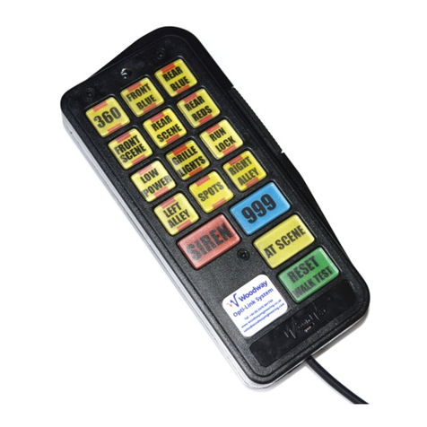
Woodway Micro-Link ZE0187 User manual

Woodway Engineering Ltd
Lower Road, Barnacle
Coventry, CV7 9LD
United Kingdom
Tel: +44 (0) 24 76 841750
Fax: +44 (0) 24 76 621796
www.woodwayengineering.com
INSTALLATION GUIDE
Micro-Link

Woodway Engineering Ltd
Lower Road, Barnacle
Coventry, CV7 9LD
United Kingdom
Tel: +44 (0) 24 76 841750
Fax: +44 (0) 24 76 621796
www.woodwayengineering.com INSTALLATION GUIDE
2
This document is intended to be used as a reference guide for
the installation and operation of the Micro-Link Control System.
Every eort has been made to ensure the reliability and accuracy
of the information contained in this manual at the time of going
to press. However, specications and procedures are subject
to change due to our constant endeavours to meet customer
requirements, and to maintain a research and development
process of continuous improvement for all Woodway products.
Woodway Engineering Ltd reserves the right to make changes
in product and documentation specications and procedures at
any time and without notice. The information contained in this
manual is believed to be reliable and accurate with regard to
the Micro-Link Control System. The company shall not be held
liable for improper installation, operation, or maintenance of the
system in circumstances where procedures and specications
have not been followed correctly.
Disclaimer
Important Installation and Safety Notes
CAUTION! Modules and connectors are not waterproof. Install modules and cables in a dry location away
from excessive heat, humidity and any components likely to damage the system.
It is the installers responsibility to ensure that;
• The method of installation does not damage or interfere with the vehicle equipment and wiring.
• If the vehicle is tted with airbags, the installation does not interfere with the operation or eectiveness
of the airbags, or this will cause the equipment to become a projectile that could cause death or injury.
• All connections to chassis are taken direct to the battery.
• Fuse ratings are changed to suit specic applications.
The proximity of certain radio equipment may interfere with Micro-Link data transmission. To reduce this
possibility, Micro-Link and radio equipment wiring should always be kept well apart and should not, under
any circumstances, be harnessed or fastened together.
The installers should supply all mounting xings.
It is the user’s responsibility to ensure that;
• The system is used in a safe and responsible manner to ensure the safety of both themselves, their
passengers, other road users and pedestrians.
• The system and its installation are properly maintained to ensure its eective operation.
WARNING! Failure to follow these safety precautions and instructions could result in damage to the product
or vehicle, and/or serious injury to your passengers.

Woodway Engineering Ltd
Lower Road, Barnacle
Coventry, CV7 9LD
United Kingdom
Tel: +44 (0) 24 76 841750
Fax: +44 (0) 24 76 621796
www.woodwayengineering.com INSTALLATION GUIDE
3
System Connection Diagrams
SW
4
SW
1
SW
5
SW
2
SW
6
SW
3
SW
7
SK
1
Grey
External ‘999’ Input +12V Momentary
Data Output to Interface Unit
0v
+12Vdc
Black
Red
Yellow
Data Input from Keypad
11 8
6 7
Pin 8 is a permanent UNFUSED
output. This pin is for test
purposes only and is not
intended to be used for
equipment supply.
Grey
I
Data Output to an additional
nterface Unit (Dip switch 1 in
the ON position enables the
additional unit)
Grey
+12Vdc Fused @ 25A
0v
DIP SWITCHES
BOTH SWITCHES SHOULD BE
SET TO THE OFF POSITION
Black
Red Permanent +12V 5A output when
system isin ‘Wake Up’ mode.
No output when in ‘Sleep Mode’.
See 4.3
Use to supply Auxiliary equipment.
Outputs 1 –6.
Outputs +12V. Use to control
external equipment.
Maximum Load 5A per outlet.
Maximum Total Load 15A
Each output must be fused
appropriately for the load
connected to it.
Micro-Link Keypad ZE0187
MicroLink Relay I/F ZE0210
Dimensions:
103 x 52 x 25
The Micro-Link keypad draws 82.5mA @13.8V when all switches are illuminated and 7.2mA @13.3V
when asleep.

Woodway Engineering Ltd
Lower Road, Barnacle
Coventry, CV7 9LD
United Kingdom
Tel: +44 (0) 24 76 841750
Fax: +44 (0) 24 76 621796
www.woodwayengineering.com INSTALLATION GUIDE
4
The Micro-Link keypad operates much like the larger Opti-Link
keypad. The major dierence is that there is only one large key,
performing 3 functions instead of separate Pursuit, Arrival and
Reset keys. The associated Interface/Output Receiver has 6 high
current output stages for controlling external equipment.
Introduction
Installation Requirements and System Limitations
The Micro-Link System is designed for 12-volt operation only.
The Interface Output/Receiver unit must be mounted in
a well ventilated dry location and away from heat sources,
preferably on a metal surface to conduct heat away. UNDER NO
CIRCUMSTANCES SHOULD THE UNIT BE MOUNTED INTO
AN ENCLOSED SPACE WHICH WOULD ALLOW HEAT TO
BUILD UP
Maximum output per relay – 5 Amps.
Maximum total output – 15 Amps
EACH OUTPUT MUST BE FUSED APPROPRIATELY FOR THE
LOAD CONNECTED TO IT.
Pursuit / Arrival / Reset
External ‘999’ Input
Walk Test
Sleep / Wake-up / Sleep Test
Audio / Visual Warnings
Low Light Keypad Dimming
Operation
In normal operation the large key, SW7, functions as a reset
switch. If no channels are selected, pressing SW7 will cycle
between a pre-dened Pursuit Setting, an Arrival setting and
nally a Reset. When in Pursuit mode the key will light blue.
When in Arrival mode the key will light red.
Connecting pin 4 on the keypad connector to +12V via an
external momentary switching source will enable the Pursuit
setting on the keypad.
Pressing and holding the large button, SW7, when not in either
Pursuit or Arrival mode initiate a walk test. Each channel will then
be lit individually for a few seconds allowing a test of all outputs.
The unit will automatically go to sleep after an hour if no
channels are selected and the supply voltage is less than 13.5
volts (i.e. the engine is not running).
The unit will wake-up when a key is pressed or when the supply
voltage exceeds 13.5 volts.
For test purposes the unit can be put to sleep by pressing and
holding SW6 and SW7 for a few seconds.
As a channel on reminder, the warning LED will ash and the
unit will beep every 30 seconds whenever a channel is on. The
warning LED will ash continuously when the battery voltage falls
below a critical level 9.5volts.
Finally the LED will light continuously when the programming
lockout is disabled.
When the ambient light level falls below a pre-set level the
keypad illumination will automatically dim. This is controlled by
the LDR (light dependent resistor) adjacent to SW1. DO NOT
COVER THIS DEVICE.
LDR
Warning Led
SW1 SW2
SW4 SW5
SW3
SW6
SW7
Keypad Layout

Woodway Engineering Ltd
Lower Road, Barnacle
Coventry, CV7 9LD
United Kingdom
Tel: +44 (0) 24 76 841750
Fax: +44 (0) 24 76 621796
www.woodwayengineering.com INSTALLATION GUIDE
5
Programming
Reprogramming and the Programming Lockout
Programming Pursuit / Arrival Settings
Programming Strobe Functionality
Programming Momentary Action
Global Reset
Before the unit can be programmed, the programming lockout
must be disabled. Pressing and holding all the switches except
channel 5 will deactivate the programming lockout for 5 minutes.
Whilst the programming lockout is disabled the warning LED will
remain continuously lit. If power is removed, or the unit is put to
sleep the unit will return to the locked mode.
Disable the programming lockout as described above.
When in Pursuit or Arrival mode, pressing and holding the large key, SW7, will allow programming of each mode. The key must be
held for a number of seconds until the blue (Pursuit) or red (Arrival) start to ash. The leds will ash for 30 seconds in which time
the required channels can be switched on/o. After this time the unit will store the new settings. Programming can be cancelled by
pressing the large button again once (reset).
The buttons SW1, SW2 and SW3 can be made self-cancelling in two dierent ways.
• Self Cancelling - Only one button can be active at one time.
Pressing and holding the large button, SW7 and SW1 will enable/disable the self-cancelling mode.
• Special Setting - Operating SW1 only also activates/deactivates SW2 and SW3.
Pressing and holding the large button SW7 and SW2 will enable/disable the special setting.
Any button can be made momentary. This is achieved by pressing and holding SW7 and SW4 until the large button will ash blue
and red. This indicates that the unit is in momentary programming mode. Any channel can now be activated. After 30 seconds, any
channel lit will become momentary.
If the programming needs to be un-done, the unit can be returned to the factory default setup by pressing and holding SW7 and SW3
for 5 seconds.
Key held
Key not held

Woodway Engineering Ltd
Lower Road, Barnacle
Coventry, CV7 9LD
United Kingdom
Tel: +44 (0) 24 76 841750
Fax: +44 (0) 24 76 621796
www.woodwayengineering.com INSTALLATION GUIDE
6
Notes

Woodway Engineering Ltd
Lower Road, Barnacle
Coventry, CV7 9LD
United Kingdom
Tel: +44 (0) 24 76 841750
Fax: +44 (0) 24 76 621796
www.woodwayengineering.com INSTALLATION GUIDE
7
Notes

Woodway Engineering Ltd
Lower Road, Barnacle
Coventry, CV7 9LD
United Kingdom
Tel: +44 (0) 24 76 841750
Fax: +44 (0) 24 76 621796
www.woodwayengineering.com
Made in the UK ISO 9001:2015 Certied 2 Year Warranty
This manual suits for next models
1
Table of contents
Other Woodway Control System manuals
Popular Control System manuals by other brands

Roger
Roger MCT80M operating manual

Pentair
Pentair SPACOMMAND CP3800 Series Installation and user guide

Carrier
Carrier PRO-DIALOG PLUS 50AZ Installation, operation and maintenance instructions

Vaillant
Vaillant 0020236294 operating instructions

Raven
Raven Viper Pro Installation & operation manual

Frico
Frico ADEA manual