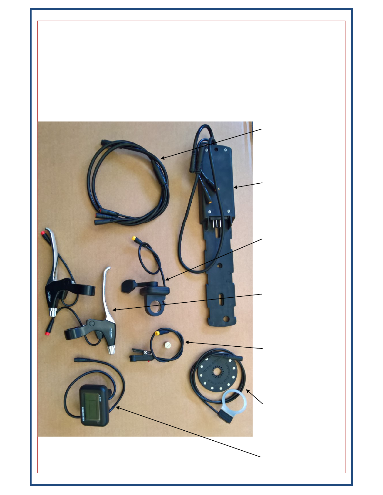
Woosh Hub Kit Assembly instructions

1
Important: For your own safety you must read this man-
ual before attempting to fit any part of the motor kit to
your bike. You must also ensure that you fit the kit in
strict accordance with the instructions in this manual.
Hub Kit Fing Guide
36V/HL

2
Before you start the installaon of your kit, please read the following:
This kit is intended to be ed by someone who is competent and experienced at ng electric kits to
bikes. If you are not experienced and/or lack the necessary tools to complete any of the procedures in
this manual, you should seek the advice of a professional who can t the kit for you. If necessary, call us
on 01702 684444 or email us at [email protected] and we will try and put you in touch with
someone in your area that has the necessary experse to properly t your kit. You will of course need to
pay for the technician to install your kit, these costs are not covered by Woosh Bikes.
There are several dierent types of pedelec sensor, we would normally have determined which type is
suitable for your bike before you nalised your order. If we didn’t, please contact us before aempng
to t your kit.
Warranty Terms:
If your kit is ed by a professional installer, it will be covered by our standard one year warranty, which
means that in the event of a failure, you would rst need to have the person that installed your kit con-
rm the issue and likely cause, then you (or the installer) would need to contact us and provide us with
the details of the fault. If the issue cannot be resolved over the phone or via email, then you would need
to return the faulty part to us at your expense. We will then repair or replace the faulty part and send it
back to you at our expense. If the kit was not ed by a professional and/or the failure that has occurred
is due to poor/incorrect installaon, or the kit has been used improperly, the warranty will be voided.

3
What’s in the Box
Ensure that you have all the parts listed below before going any further, if there are any missing parts,
contact us on 01702 435566.
The motor kit comprises of a motor wheel with hub motor, a baery cradle with integral controller, a
baery, a charger, modular one-cable system, pedal-assist disc and sensor, speed sensor (and magnet) ,a
thumb throle, brake levers and KingMeter J-LCD. Ensure that you have all of these items, a photo of the
items is show below so you can easily idenfy each of the parts. Not shown in the photo below are the
baery itself and the motor wheel (which will dier depending on the type ordered), ensure you have the
complete kit before you start.
Modular cable
Baery cradle/controller
Thumb-throle
Brake levers
Speed sensor and magnet
Pedelec sensor
KingMeter LCD

4
Installaon of the various Pedelec Sensor types
There are three types of sensor kit that can be used, two that t on the right side of the bike between the
chain-ring and frame, and the other le-side sensor which slots into the end of the boom bracket.
The standard right-side pedelec kit consists of two parts, these are the sensor itself and the PAS disc. You
will need to remove the boom bracket and then slide the sensor ring into place as shown below. With
the sensor in posion, you can ret the boom bracket. With the boom bracket re-installed, slide the
PAS disc over the spindle so that it is as close as possible to the sensor, without actually touching it.
You need to ensure that the disc is the correct way around on the spindle, otherwise you will nd that the
motor kicks in when you pedal backwards! The disc should be ed such that the arrows on the disc are
on the le side.
The supplied sensor/disc may dier slightly from the one shown above, but the installaon procedure will
be the same.
A variaon of this same arrangement is shown below, it sll uses a PAS disc much like the above, but uses
a sensor which is mounted onto the downtube instead.
Sensor To controller

5
Le-side pedelec sensor
The le slide sensor slides over the spindle and into the toothed part of the boom bracket. It is not com-
pable with all boom brackets however. Some that aren’t compable include the boom brackets with
the plasc cups. Although they look very similar, the le-side PAS will not slot into these. It must be a
boom bracket with a metal cup—see pics below. In some cases you may nd that you cannot slide the
sensor down far enough, if this is the case, you can either swap the boom bracket for a dierent model
(we can advise you on a suitable unit), or contact us to see if a right-side PAS is a possibility for you. The
space between the rear face of the crank and the boom bracket needs to be around 5mm or more, if it
is less, you may need to shave a lile o the rear face of the crank to avoid crushing the PAS when you re-
t the crank.
Ensure that your boom bracket is similar to the one shown below, and then slide the sensor into posi-
on. It may need a reasonable amount of force to push it all the way on.

6
Le-side pedelec sensor cont.
Slide the larger rubber washer over the spindle and then re-t the crank.

7
Pedelec Sensor for Octalink type crank sets:
The diameter of the Octalink axle is greater and so the regular pedelec disc cannot be used. We are how-
ever able to provide a soluon for this type of boom bracket. We supply a modied pedelec disk which
has a larger hole in the centre which can be used, it needs to be secured to the back of your smallest
chain-ring in the case of double or triple rings. The sensor itself is then aached to the base of the seat
tube.
Pedelec disc
With the sensor in place as per the photo above, it now needs to be secured, the way you achieve this
may vary depending on your specic bike. In this example, we’re just using some cable-es.
The sensor is mounted at the base of the seat tube. The sensor is supplied with a single cable-e which is
use to secure the sensor to the seat tube.
Sensor To controller
Cable-e for
securing to
seat tube.

8
Baery/Controller
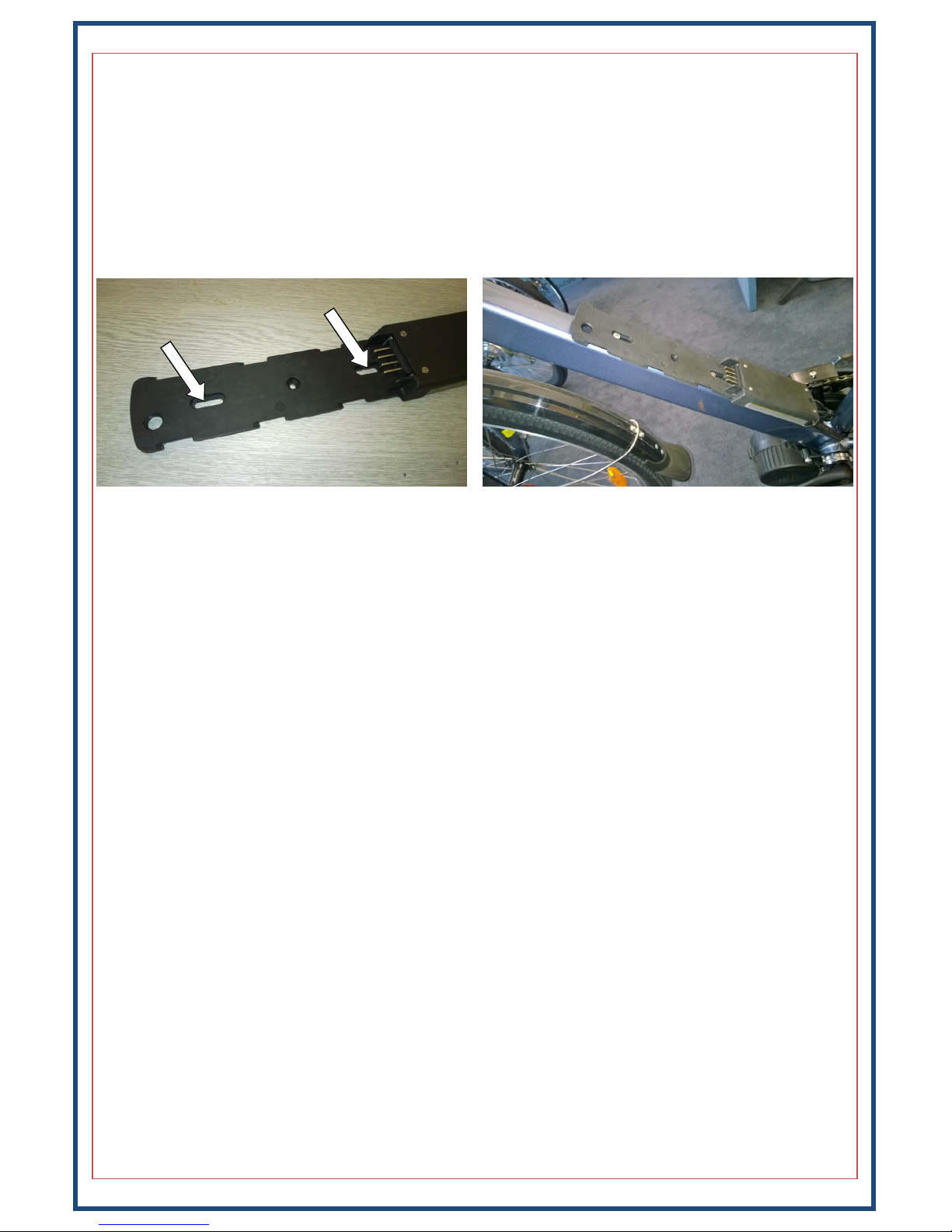
The HL baery cradle/controller included with this kit mounts on your down-tube, where your bole
holder xings would normally be. If the bike does not have these xings or they are not in a suitable posi-
on, you can t riv-nuts (supplied) to allow you to mount the baery cradle. Ensure that you mount the
cradle high enough up the down-tube that the cradle doesn’t foul on the chain-ring. You will also need to
ensure that there is sucient clearance at the top end of the baery, the baery needs to be slid up-
wards (towards the front of the bike) a lile when removing it. Also, be careful not to mount the cradle
too low, or you may nd that the baery hits the seat-tube before it’s fully engaged on the cradle.
Don’t forget to use the supplied washers, if you bolt the cradle to the frame without using the washers,
the plasc will deform and eventually break.
Once the cradle has been secured to the frame, t the baery in place and double-check that that you
have enough clearance at either end, and adjust the posion of the base if necessary. You should then
remove the baery and connue on with the installaon of the kit. Do NOT connue the installaon
with the baery in place. You should only re-t the baery when all leads have been correctly terminat-
ed/secured and the kit installaon is complete. If you leave the baery aached, you may accidentally
short something and damage the baery and/or kit components.
Motor Wheels:
There are several dierent opons for the motor wheel. The Front-BPM opons require torque arms to
be ed, and the rear wheel opons will need the cassee or freewheel from your exisng wheel to be
ed to the new motor wheel.

9
Motor Wheel
Remove the exisng rear wheel and swap the tyre, tube and freewheel/cassee to the new motor wheel.
You must ensure that the motor cable where it exits the spindle, points downwards towards the ground,
see below for photos showing how the wheel should be ed and the correct orientaon of the cable.
Once the wheel is properly installed, slide the rubber covers in place and secure the motor cable to the
frame using cable–es. The rubber cover for the side where the cable exits the spindle will need to be slid
along the cable, and it should be ed in such a way that the hole in the rubber cover keeps the motor
cable poinng downwards as much as possible—see below. Also ensure that the metal coil/sheath is all
the way down the cable so that it protects the cable from the somewhat sharp edges where the cable ex-
its the motor.
The red arrow on the diagram above shows the typical route for the motor cable, with the quick-release
connector (in the cable) indicated by the solid red box.
FRONT Motor Wheel
Remove the exisng wheel and swap the tyre and tube to the new motor wheel. If you have purchased
this kit and cannot carry out one or more of the procedures in this manual or do not have the necessary
tools to complete the installaon, you should seek the advice of a professional who can t the kit for you.
You must ensure that the motor cable where it exits the spindle, points downwards before looping back
up, to form a drip –loop, this is to stop water running down the cable and collecng at the cable exit.
Once the wheel is properly installed, connect the motor cable and then secure the motor cable to the
fork using cable–es.

10
Handlebar Components:
The thumb-throle, brake levers and display unit need to be mounted to the handlebars. The installaon
procedure for these parts may vary a lile from bike to bike, but follow the guide below for a general
overview.
The display would normally be ed to the le side of the handlebars just to the right of the grip, this way
the buons can be easily reached with a thumb . To t the thumb-throle, slide the grip o the right side,
loosen the exisng components such as the shier, brake lever etc. then slide the thumb-throle on and
then secure it (and the other components) in posion.
Depending on the conguraon of the bike, it may be more praccal to mount the throle and display in
slightly dierent locaons or on opposite sides.
If you have hydraulic brakes or brake levers which have an integral gear shier, you will need to use a
dierent brake sensor arrangement. The way these sensors work is that as the magnet is moved away
from the sensor, the brake cut-out is acvated. A typical installaon would look similar to the below.
The next step is to run the modular cable (for the LCD, throle and brake cut-outs) from the front of the
bike back to the controller .
Sensor
Magnet

11
Handlebar Components cont.
You must ensure that there is enough play in the cables so that they do not get stretched or pulled when
the handlebars are rotated.
The throle cable and LCD connectors are colour coded and should be mated with the matching colours
on the modular cabling. There are arrows on each connector which indicate how to line them up, see
photos below.
Ensure that the arrows line up on both sides before pushing the connectors rmly together, be careful
with them and don’t force them or you may bend/damage the pins. Also be sure to mate the cables with
the matching coloured connectors.
If you have too much slack in the cables, you will need to secure them with cable-es as dily as possible.
Ensure that none of the cables are hanging loosely or in a posion where they may get caught on any oth-
er parts whilst the bike is being ridden.
Note: The display connectors are green in some cases rather than black.

12
Fing the Speed Sensor:
The speed sensor consists of two parts, the sensor itself and a magnet that is aached to one of the
spokes. The sensor is normally ed at the rear. The speed sensor is mounted approximately half-way
along the inside of the chain stay as shown in the diagram below (in Red). Simply secure the sensor to the
frame with cable-es, it may be necessary to t a spacer between the sensor and the frame to bring the
sensor closer to the magnet, otherwise it may not detect the magnet as it passes. Posion the magnet so
that as the wheel rotates, the magnet passes the rear-most (cylindrical shaped) part of the sensor as
shown below-right.
Run the cable along the chain stay as indicated in RED above, securing it with cable-es and ensuring that
the cable is clear of the wheel/tyre. See the next page for the various connecons to the controller.

13
Controller Connecons:
Exing from the boom of the baery base/cradle are four cables, these are for the speed sensor, the
motor wheel, the pedelec sensor and the modular cable. The modular cable runs up to the handlebars
and connects to the display unit, the thumb-throle and the brake levers. All of the connectors have ar-
rows on them that need to be correctly aligned before pushing the connectors rmly together.
Motor cable
Modular cable
(to handlebars)
Speed sensor
Pedelec sensor

14
Warning:
The display comes pre-configured and limited to 15mph. Incorrect settings could cause damage to the kit
components and also result in a bike that is not UK road legal. Modifications made to the controller config-
uration will void your warranty if found to be a contributing factor to a failure.
Turning Control Module On/Off
To turn on the control module press and hold the top (Mode) button. Press and hold the same button to
turn off the module and disable all electric features of the bike.
Turning Backlight On/Off
To turn on the display backlight, press and hold the “Up” button. Press and hold the same button to turn it
off.
Varying Pedal Assist Level
To alter the level of assistance provided simply press the Up/Down arrows to cycle through the 5 levels of
assistance. Level 1 offers the least assistance while level 5 offers the greatest assistance.
Speed Display Mode
There are three different modes for the speed display, these are current speed, average speed and maxi-
mum speed. To switch between these modes, press and hold the “Up and Mode” buttons for approx. 1
second to cycle through the modes.
Walking Mode/Start– Aid
The bike also supports a walking mode which is basically a very slow mode allowing you to walk next to
the bike at approx. 6m/h. This is activated by pressing and holding the “Down” button. As soon as the but-
ton is released, the bike will stop. This can be used to start off, if you find it difficult from a stand-still.
Display Mode
To switch between Odo (overall distance travelled) and Trip mode (current trip distance travelled), press
the “Mode” button. To reset the trip computer press and hold both the top and bottom buttons.
LCD—Control Panel
The display has many advanced features and modes, these include back-lit display (for night riding), indi-
cator options for max speed, average speed and current speed and a battery power indicator. It also fea-
tures a walking mode which is used when you want to wheel/push the bike, this is basically a very low
speed mode which is activated by pressing and holding the minus (-) button, this can also be used as a
start-aid.
On/O/Mode buon
(+) or UP Buon
(-) or Down Buon
Baery Level
Speed
Odometer
Assistance Level

15
Baery care:
Some care is needed to ensure that the baery performs at its best and lasts as long as possible. All
baeries age over me, and the way that they age is that the range you can achieve will gradually de-
crease. Follow the instrucons below to ensure your baery performs as well as possibly for as long as
possible. Charge the baery once or twice per week as needed.
Do NOT charge the baery in extremely cold condions. The baery can be easily removed from the bike
and charged whilst o the bike if it’s more convenient. Allow the baery to warm up to room tempera-
ture before charging.
If the baery is not in regular use i.e. over the winter, you should charge the baery for around 10
minutes ever three to four weeks. When the bike is to be put back into service, fully charge the baery as
normal. Try and keep the baery around two thirds full when not being used.
General baery care:
Do not aempt to open the outer casing of the baery.
Do not aempt to repair the baery.
Do not immerse the baery in water.
Keep the baery away from children.
Do not drop, pierce or otherwise damage the baery.
Ensure the baery is not exposed to temperatures above 55 degrees Celsius or extreme humidity.
Do not use the bike in an environment where temperatures are below -5 or greater than 55 degrees Cel-
sius.
Lithium baeries do not perform at their best during the winter months, and so the range may vary from
one season to another.
Charging the baery:
Plug the charger into the socket on the right-side of the baery, then plug the other end into the mains
socket and switch it on. While the baery is charging, the LED on the charger will glow RED, when charg-
ing is complete, the LED will go GREEN. If the charger is on but not aached to the baery, the LED will
also be GREEN. If you experience a sudden drop in capacity, run the baery down quite low, then fully
charge it. Once full, leave the charger switched on and connected to the baery for a further two hours.
This will help to balance the cells internally and restore normal operaon.

16
Baery operaon:
The HL baeries come in two slightly dierent variants.
Baery Type 1
The rst baery-type is always on, and when the buon is pressed, it just shows current state of the
baery—the more lights illuminated, the more full the baery is.
Baery Type 2
The second type, while physically idencal, the buon on this one is a mul-funcon buon. The buon
is used to turn the baery on and o, as well as to indicate the status of the baery.
With the baery o, pressing the buon will turn the baery on, this indicated by a single green LED.
Pressing and holding this buon for a three seconds will turn the baery o.
With the baery already on, briey pressing the buon will show the baery status.
If the baery is le switched on, but unused, it will automacally turn o aer a while.

17
© 2018 Woosh Bikes Limited
Woosh Support:
Our contact details are below.
It can sometimes be useful to see the issue you have, so if possible, email a couple of photos illustrating
the problem and we’ll normally get back to you within an hour or two (on weekdays).
Support staff are not available at the weekends, though if you send an email, it will normally be read and
replied to on the following Monday (except on bank holidays).
Email: kits@wooshbikes.co.uk
Telephone: 01702 435566
Support staff are available 10am to 5pm Monday to Friday.
Table of contents
Other Woosh Bicycle Accessories manuals