Woosh HL30 Assembly instructions

1
Important: For your own safety you must read this
manual before attempting to fit this kit. You must also
ensure that you fit the kit in strict accordance with the
instructions in this manual.
Fing Guide for
HL/G30 Hub Kits

2
Before you start the installaon of your kit, please read the following:
This kit is intended to be ed by someone who is competent and experienced at ng electric kits to
bikes. If you are not experienced and/or lack the necessary tools to complete any of the procedures in
this manual, you should seek the advice of a professional who can t the kit for you. If necessary, call us
on 01702 435566 or email us at [email protected] and we will try and put you in touch with
someone in your area that has the necessary experse to properly t your kit. You will of course need to
pay for the technician to install your kit, these costs are not covered by Woosh Bikes.
Warranty Terms:
If your kit is ed by a professional installer, it will be covered by our standard one year warranty, which
means that in the event of a failure, you would rst need to have the person that installed your kit con-
rm the issue and likely cause, then you (or the installer) would need to contact us and provide us with
the details of the fault. If the issue cannot be resolved over the phone or via email, then you would need
to return the faulty part to us at your expense. We will then repair or replace the faulty part and send it
back to you at our expense. If the kit was not ed by a professional and/or the failure that has occurred
is due to poor/incorrect installaon, or the kit has been used improperly, the warranty will be voided.

3
What’s in the Box
Ensure that you have all the parts listed below before going any further, if there are any missing parts,
contact us on 01702 435566.
The motor kit comprises of a motor wheel with hub motor, a baery cradle with integral controller, a
baery, a charger, modular cable/loom, pedal-assist sensor, a thumb throle, brake sensors and a King-
Meter KM529 LCD. Ensure that you have all of these items, a photo of the items is show below so you can
easily idenfy each of the parts. Not shown in the photo below are the baery itself , the charger, and the
motor wheel (which will dier depending on the type ordered), ensure you have the complete kit before
you start.
KM529 LCD
Thumb-throle
Controller/
Baery cradle
Inline brake
sensors
Loom/Modular
cable
Pedelec sensor
HL Kit
G30 Kit
As above but with dierent
baery and cradle

4
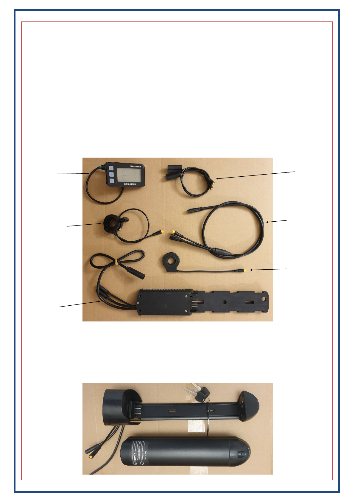
Installaon of the various Pedelec Assist Sensor (PAS) types
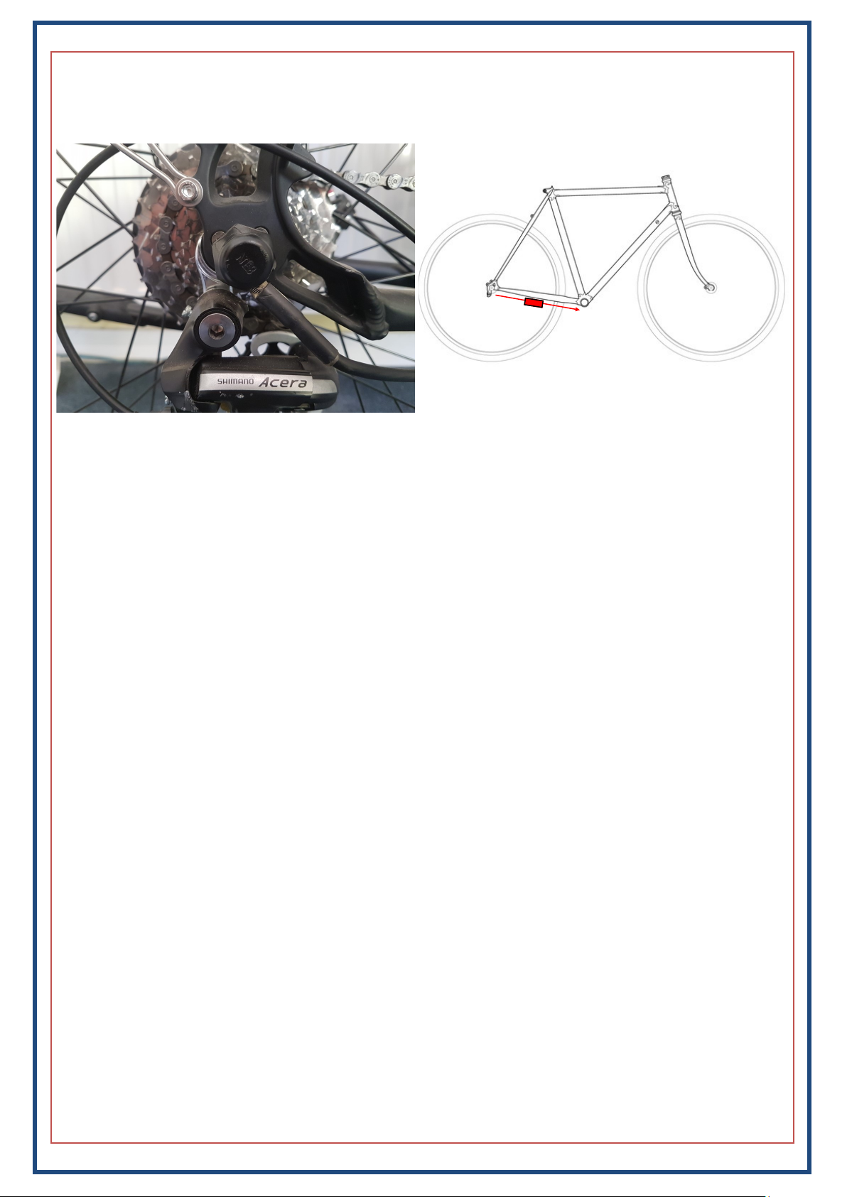
There are three types of PAS that can be used, two that t on the right side of the bike between the chain
-ring and frame, and the le-side sensor, which slots into the end of the boom bracket.
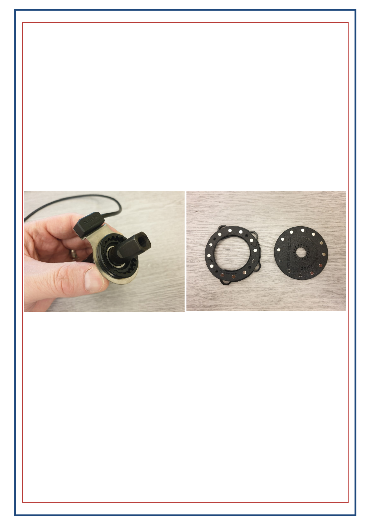
The right-side PAS kit consists of two parts, these are the sensor itself and the PAS disc. There are two
dierent opons for the disc/magnet-ring part of the PAS kit (see below-right), depending on whether
you have a square taper boom bracket or something else. In all cases, the sensor ring is mounted be-
hind the lip of the xed cup, or behind the right bearing shell (in the case of a BB with external bearings).
The PAS disc for square taper boom brackets is simply slid down the axle so that it is close to, but not
touching the sensor. For all other types of boom bracket, you would need to use the alternate disc
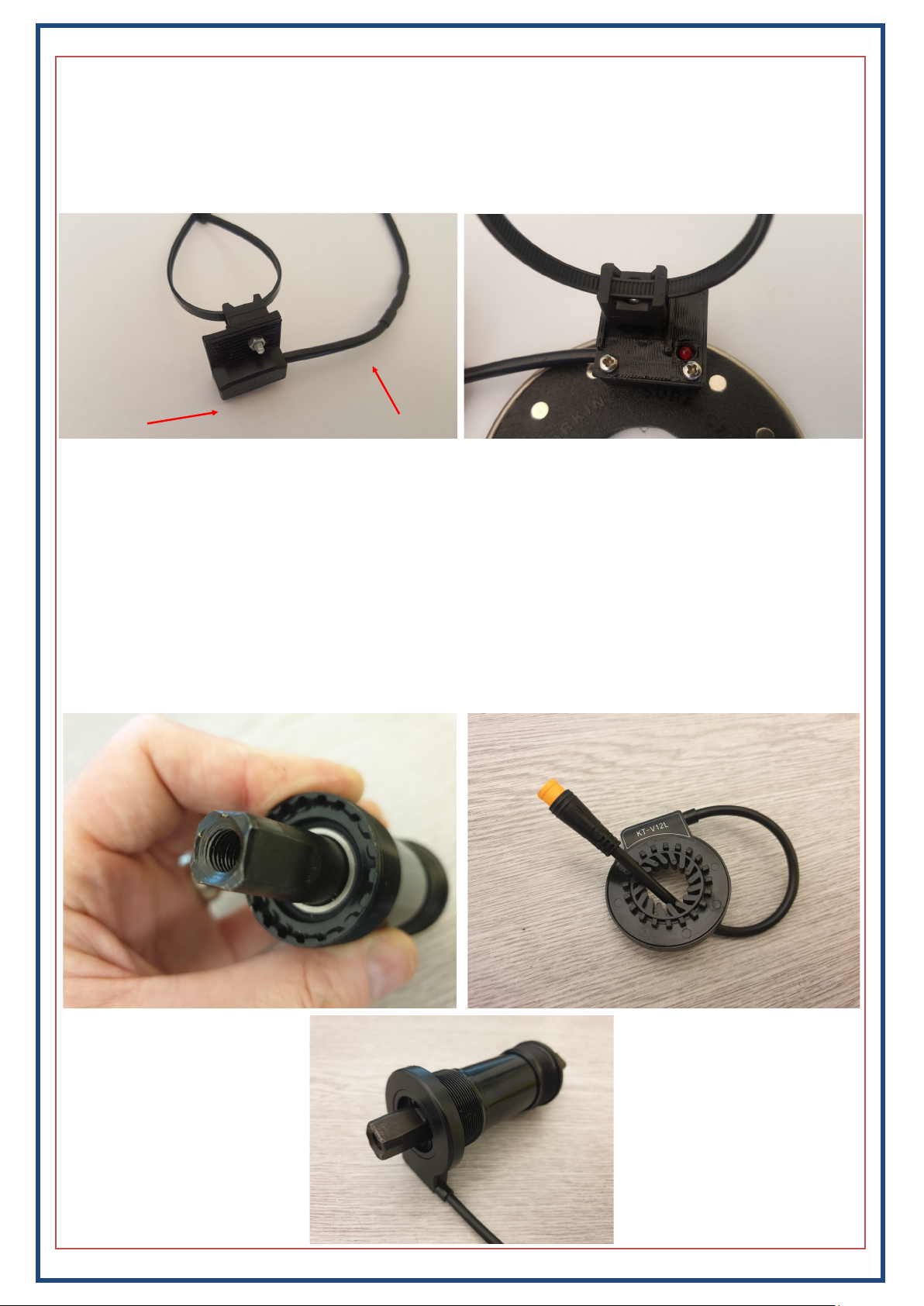
which comes in three parts—the two halves of the magnet ring, and the support/mounng plate. Ideally,
the mounng plate is cable-ed to the smallest chain ring (using the loops around the outside of the
plate), and the two halves of the magnet ring are then glued to the plate. In some cases, there is not al-
ways enough room to do this, and the ring needs to be bonded directly to the smallest chain ring and/or
you may need to use the seat-post mounted sensor instead—see next page.
Installaon Notes:
You need to ensure that the disc is the correct way around on the axle. The disc should be ed such that
the arrows on the disc are on the le side (facing the sensor). For other non-square taper boom
brackets, the two halves of the magnet ring only t on the mounng plate one way, so you can’t get it
wrong.
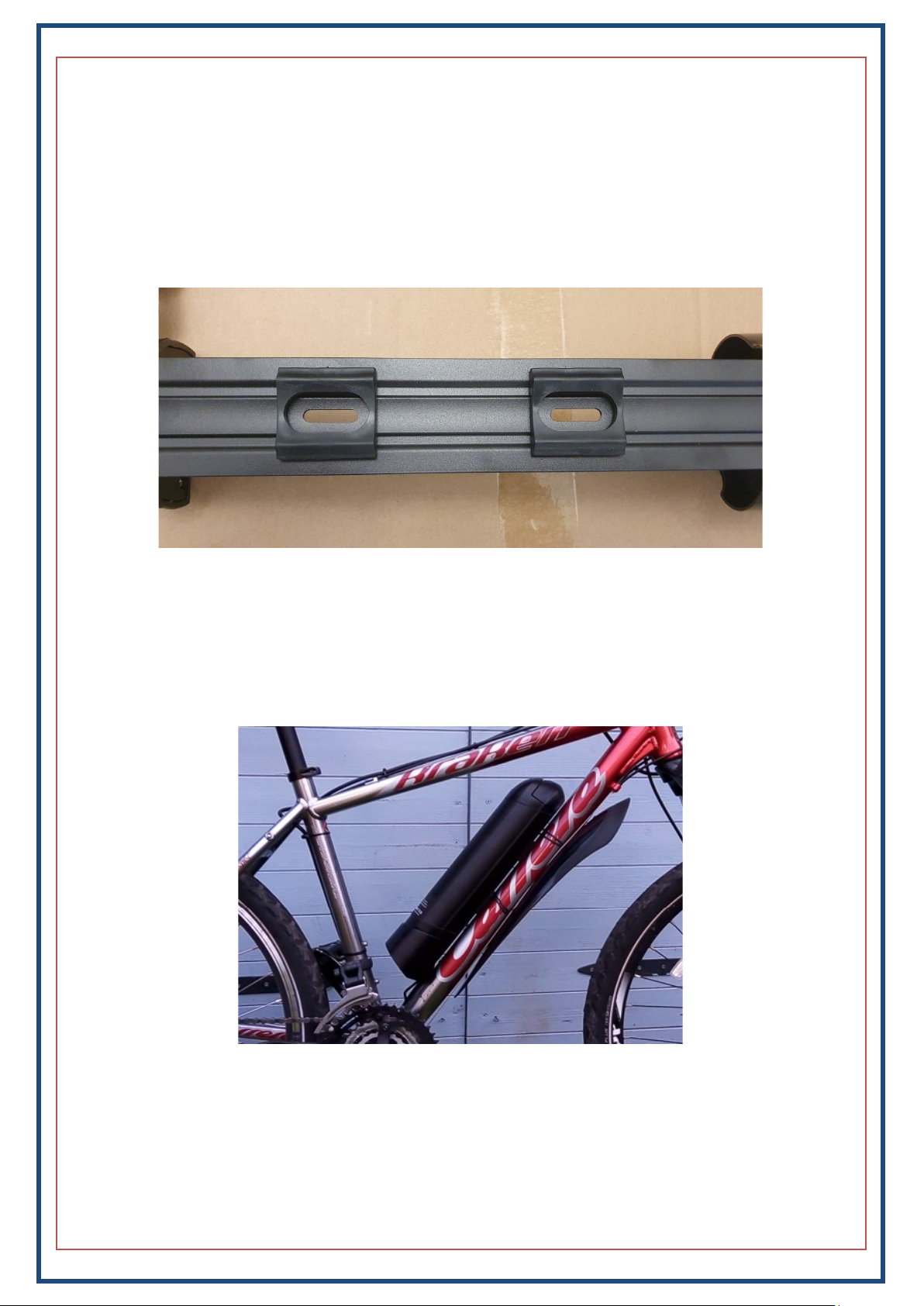
With external bearing shells, it is somemes necessary to t a spacer behind the shell, we can supply
these, but in many instances, you can just take one from the le side and move it over to the right.

5
Le-side pedelec assist sensor (PAS):
The le-side PAS slides down the axle on the le side of the boom bracket and meshes with the splines.
This PAS is not suitable for all square-taper boom brackets, if you have a plasc cup (as opposed to a
metal cup), the le-side PAS will likely not be suitable. Although they look very similar, the le-side PAS
will not mesh with the plasc cup.
The le-side PAS requires a gap of 7mm between the rear face of the le crank and the boom bracket. if
it is less, you may need to shave a lile o the rear face of the crank to avoid crushing the PAS when you
re-t the crank. Alternavely, we usually have in stock 127mm boom brackets that in most cases would
give you the space you require.
Sensor To controller
Seat-post mounted PAS:
The seat-post mounted sensor is shown below and is simply cable-ed to the lower part of the seat tube.
If the sensor isn’t sing back far enough, it is possible to remove one of the plasc spacers on the rear of
the mounng buy simply undoing the bolt and then removing the lower of the two spacers. The sensor
should be posioned as shown below-right, so that the magnets pass by the correct part of the sensor.

6
HL Baery/Controller
The HL baery-cradle/controller included with this kit mounts on your down-tube, where your bole
holder would normally be. If the bike does not have these xings or they are not in a suitable posion, you
will need to t riv-nuts (supplied) to allow you to mount the baery cradle. Ensure that you mount the
cradle high enough along the down-tube so that the cradle doesn’t foul on the chain-ring. You will also
need to ensure that there is sucient clearance at the top end of the baery, the baery needs to be slid
upwards a lile when removing it. Be careful not to mount the cradle too low, or you may nd that the
baery hits the seat-tube before it’s fully engaged on the cradle. The space required is 38cm x 10cm.
Don’t forget to use the supplied washers and rubber supports (shown below). If you bolt the cradle to
the frame without using the washers/supports, the plasc will deform and eventually break.
Motor Wheels:
There are several dierent opons for the motor wheel, front, rear, 26”, 700c, cassee hubs, freewheel
hubs etc. We would normally have idened the motor/wheel that would best suit your bike before the
order was placed.
Once the cradle has been secured to the frame, t the baery in place and check that it ts correctly.
Next, remove the baery from the cradle and connue on with the installaon of the kit. Do NOT conn-
ue the installaon with the baery in place. You should only re-t the baery when all leads have been
correctly terminated/secured and the kit installaon is complete. If you leave the baery aached, you
may accidentally short something and damage the baery and/or kit components.

7
G30 Baery/Controller
The G30 baery-cradle/controller included with this kit mounts on your down-tube, where your bole
holder would normally be. If the bike does not have these xings or they are not in a suitable posion, you
will need to t riv-nuts (supplied) to allow you to mount the baery cradle. Ensure that you mount the
cradle high enough along the down-tube so that the cradle doesn’t foul on the chain-ring. The baery re-
quires a space of 18cm x 7.5cm
Don’t forget to t the rubber spacers/supports (shown below).
Once the cradle has been secured to the frame (using the supplied bolts), t the baery in place and
check that it ts correctly and that the lock is funconing. Next, remove the baery from the cradle and
connue on with the installaon of the kit. Do NOT connue the installaon with the baery in place.
You should only re-t the baery once all of the cables have been correctly terminated/secured and the
installaon of the kit is complete.
Motor Wheels:
There are several dierent opons for the motor wheel, front, rear, 26”, 700c, cassee hubs, freewheel
hubs etc. We would normally have idened the motor/wheel that would best suit your bike before the
order was placed.

8
85SX
Important note for purchasers of the 85SX motor wheel
You must NOT use rotor bolts longer than 10mm. Longer
bolts will protrude too far into the motor housing and will
damage the motor.

9
Motor Wheel
Swap the tyre, tube and freewheel/cassee (in the case of a rear wheel) from your original wheel over to
the motor wheel.
The wheel comes with the nuts and washers that you will need, they should normally be ed in the or-
der shown below, but somemes it is necessary to re-arrange them, or to t addional washers to ensure
the wheel is correctly aligned. The an-rotaon washer for instance, can be ipped around and ed on
outside of the drop-outs if necessary. If you have disc brakes, loosen the two bolts indicated below-le
before ng the wheel to the bike. This will allow you to make any minor adjustments immediately. If
you are experienced, you can remove the callipers if you prefer and re-t them later. Don’t forget to ght-
en the calliper bolts aer the wheel is correctly ed and the rotor correctly aligned.
The normal order for the nuts/washers is as below-le, but as menoned above, it may be necessary to re
-arrange them to suit your parcular bike. On the drive-side, try to leave enough space so that if the chain
were to come o, it won’t get jammed between the frame and cassee/freewheel.
Ensure that the motor cable exits downwards, and also ensure that the metal coil is far enough down the
cable so that it protects the cable from the edges where it exits the spindle. It can be slid down further by
hand if it’s not in the correct posion.
Thick washer Torque washer
Thin washer Nut
There is a cut-out where the cable exits the axle.
This cut-out and the cable should face downwards
towards the ground. In the case of a front wheel,
the cable should also exit downwards before loop-
ing back up towards the fork. This is to prevent wa-
ter collecng at the aperture.

10
Motor Wheel cont…
To complete the installaon of the wheel, t the nut covers. The le side cover simply pushes on, the
drive side cover should be slid down the cable and ed as shown below-right.
The red arrow on the diagram above-right shows the typical route for the motor cable (in the case of a
rear hub conversion), with the quick-release connector (in the cable) indicated by the solid red box. Re-
member to properly secure these cables to the frame using cable-es before riding the bike.
Cable orientaon:
It is possible to t the front motor wheels the wrong way around, and so to avoid any mishaps, please re-
fer to the table below, and ensure that the wheel is ed correctly. For all XF07 front hub installaons,
the wheel should be ed such that the motor cable exits the hub on the right side.
Motor Wheel Orientaon
XF07 Front Hub Cable exits the right side of the hub
XF08 Rear Hub Cable exits the right side of the hub
SWX02 Rear Hub Cable exits the right side of the hub
DGW22C Rear Hub Cable exits the right side of the hub
SX85 Rear Hub Cable exits the le side of the hub
G060500DC Rear Hub Cable exits the right side of the hub
Q70 Front Hub (Brompton Kit) Cable exits the le side of the hub

11
Handlebar Components:
The display would normally be mounted on the le side. If you decide not to t the throle (a lot of peo-
ple don’t), then it is not necessary to t brake cut-outs. If you are using throle, you will need to t one of
the three types of brake cut-outs: Levers (for cabled brakes), inline sensors (for cabled brakes), hydraulic
sensors which can also be used for cabled brakes in situaons where the gear shier and brake levers are
a single unit.
To t the thumb-throle & brake levers (if being used), slide the grips o, loosen the exisng compo-
nents, and remove any that are being replaced, then slide the thumb-throle (and levers if being used) in
place and then re-ghten the bolts to secure them in place. The display has a clamp, and so should be
ed aer the other components are in posion. The throle is universal and can be ed to either side.
If you have hydraulic brakes or brake levers that have an integral gear shier, you will need to use the hy-
draulic sensors. As the magnet moves away from the sensor, the cut-out is acvated, it should be ed as
shown below.
Sensor
Magnet
Inline Sensors: Feed the brake cable though as shown below-right. Be sure to use the plasc insert
between the sensor and barrel adjuster.

12
The next step is to run the modular cable (for the LCD, throle and brake cut-outs) from the front of the
bike, to the controller .
Ensure that there is enough play in the cables so that they do not get stretched or pulled as the handle-
bars are rotated.
The connectors are all colour coded and should be mated with the matching colours on the modular ca-
bling. There are arrows on each connector which must be lined up before pushing the connectors togeth-
er. In some instances, the cable from the LCD may be green, this mates with the black/green connector.
Ensure that the arrows line up on both sides before pushing the connectors rmly together, be careful
with them and don’t force them or you may bend/damage the pins. Also be sure to mate the cables with
the matching coloured connectors.
Depending on which brake sensors/levers your kit is supplied with, the connectors on the loom may be
dierent to those shown above. If your kit was supplied with inline brake sensors, you will have three
yellow connectors, one for the throle and another for each of the inline sensors.
If you have too much slack in the cables, you will need to coli them up and secure them with cable-es as
dily as possible. Ensure that none of the cables are hanging loosely or in a posion where they may get
caught/snagged on any other parts whilst the bike is being ridden.

13
Speed Sensor:
Note: Most of the kits we supply now do not require an external speed sensor, it is built into the hub.
In these cases, you will not receive a speed sensor with your kit, and you can skip to the next page.
The speed sensor consists of two parts, the sensor itself and a magnet that is aached to one of the
spokes. The sensor is normally ed at the rear. The speed sensor is mounted approximately half-way
along the inside of the chain stay as shown in the diagram below (in Red). Simply secure the sensor to the
frame with cable-es, it may be necessary to t a spacer between the sensor and the frame to bring the
sensor closer to the magnet, otherwise it may not
Run the cable along the chain stay as indicated in RED above, securing it with cable-es and ensuring that
the cable is clear of the wheel/tyre. See the next page for the various connecons to the controller.

14
Controller Connecons:
Exing from the boom of the baery cradle are three or four cables, these are for the speed sensor, the
motor wheel, the pedelec sensor and the modular cable. The modular cable runs up to the handlebars
and connects to the display unit, the thumb-throle and the brake levers. All of the connectors have ar-
rows on them that need to be correctly aligned before pushing the connectors rmly together.
Motor cable
Modular cable
(to handlebars)
Speed sensor**
Pedelec sensor
** Note for wheels with hall-sensors (9-pin motor cable):
If your motor has hall/speed sensors built-in, you will have a 9-pin connector on the motor cable,
(instead of a 3-pin cable) and you will NOT have a cable for a speed sensor. The controller for motors
with hall-sensors will only have three cables exing from the boom of the cradle, instead of four.

15
Warning:
The display comes pre-configured and limited to 15mph. Incorrect settings could cause damage to the kit
components and also result in a bike that is not UK road legal. Modifications made to the controller config-
uration will void your warranty if found to be a contributing factor to a failure.
Turning Control Module On/Off
To turn on the control module press and hold the top (Mode) button. Press and hold the same button to
turn off the module and disable all electric features of the bike.
Turning Backlight On/Off
To turn on the display backlight, press and hold the “Up” button. Press and hold the same button to turn it
off.
Varying Pedal Assist Level
To alter the level of assistance provided simply press the Up/Down arrows to cycle through the 5 levels of
assistance. Level 1 offers the least assistance while level 5 offers the greatest assistance.
Speed Display Mode
There are three different modes for the speed display, these are current speed, average speed and maxi-
mum speed. To switch between these modes, press and hold the “Up and Mode” buttons for approx. 1
second to cycle through the modes.
Walking Mode/Start– Aid
The bike also supports a walking mode which is basically a very slow mode allowing you to walk next to
the bike at approx. 6m/h. This is activated by pressing and holding the “Down” button. As soon as the but-
ton is released, the bike will stop. This can be used to start off, if you find it difficult from a stand-still.
Display Mode
To switch between Odo (overall distance travelled) and Trip mode (current trip distance travelled), press
the “Mode” button. To reset the trip computer press and hold both the top and bottom buttons.
LCD—Control Panel
The display has many advanced features and modes, these include back-lit display (for night riding), indi-
cator options for max speed, average speed and current speed and a battery power indicator. It also fea-
tures a walking mode which is used when you want to wheel/push the bike, this is basically a very low
speed mode which is activated by pressing and holding the minus (-) button, this can also be used as a
start-aid.
On/O/Mode buon
(+) or UP Buon
(-) or Down Buon
Baery Level
Speed
Odometer
Assistance Level

16
Baery care:
Some care is needed to ensure that the baery performs at its best and lasts as long as possible. All
baeries age over me, and the way that they age is that the range you can achieve will gradually de-
crease. Follow the instrucons below to ensure your baery performs as well as possibly for as long as
possible. Charge the baery once or twice per week as needed.
Do NOT charge the baery in extremely cold condions. The baery can be easily removed from the bike
and charged whilst o the bike if it’s more convenient. Allow the baery to warm up to room tempera-
ture before charging.
If the baery is not in regular use i.e. over the winter, you should charge the baery for around 10
minutes ever three to four weeks. When the bike is to be put back into service, fully charge the baery as
normal. Try and keep the baery around two thirds full when not being used.
General baery care:
Do not aempt to open the outer casing of the baery.
Do not aempt to repair the baery.
Do not immerse the baery in water.
Keep the baery away from children.
Do not drop, pierce or otherwise damage the baery.
Ensure the baery is not exposed to temperatures above 55 degrees Celsius or extreme humidity.
Do not use the bike in an environment where temperatures are below -5 or greater than 55 degrees Cel-
sius.
Lithium baeries do not perform at their best during the winter months, and so the range may vary from
one season to another.
Charging the baery:
Plug the charger into the socket on the right-side of the baery, then plug the other end into the mains
socket and switch it on. While the baery is charging, the LED on the charger will glow RED, when charg-
ing is complete, the LED will go GREEN. If the charger is on but not aached to the baery, the LED will
also be GREEN. If you experience a sudden drop in capacity, run the baery down quite low, then fully
charge it. Once full, leave the charger switched on and connected to the baery for a further two hours.
This will help to balance the cells internally and restore normal operaon.

17
Baery operaon:
The HL and G30 baeries are eecvely always on, and when the buon at the top is pressed, it shows
the current state of the baery—the more lights illuminated, the more full the baery is.
Troubleshoong (HL Baery):
Bike cung out, display switching itself o whilst riding:
If you nd aer some months that the display/motor cuts out when riding, it is likely that the contacts on
the underside of the baery need some cleaning/adjustment. It is not normally anything more than this.
Clean out any excess grease, and then use a cocktail sck or a small at screwdriver to ex the contacts
inwards, a close-up of an individual terminal is shown above right, and shows the parts that need to be
exed. It is only necessary to do this to the outer terminals, as the middle ones are not connected.
Error 25 on the display:
This error message indicates an issue with the brake sensors. If you are seeing this error, it is likely that
the bike will not provide any assistance and the throle will not work. To gure out which sensor is at
fault, unplug one sensor and then the other unl you know which sensor is causing the problem. If you
have levers or inline sensors, the faulty one will likely need replacing. If you have the hydraulic-type sen-
sors, it is likely that the magnet has moved too far away from the sensor, and can usually be resolved just
by bringing the magnet closer to the sensor.
X
X

18
Rack baery:
The rack baeries (unlike the downtube baeries) have a switch towards the rear le of the unit which is
used to turn the baery on/o—a master-switch eecvely.
At the very end (the rear-most part) of the baery), there is small buon in the middle, pressing this
buon rmly and holding it will illuminate the LED’s either side of the buon. This is used to give a rough
indicaon of the baery status— if all LED’s are illuminated (regardless of colour) this means that the
baery is full (or thereabouts). As the baery drains, the lights will go out one by one, unl only the red
LED’s remain. If only the red LED’s illuminate when pushing the buon, the baery should be charged
soon.
The LED’s cannot ever change colour, the red LED’s will not, and cannot ever go green.
Charging the rack baeries is done in exactly the same way as with the downtube baeries, and can be
done with the baery on or o the bike. When the baery is charging, the LED on the charger will be red,
when charging is complete, the LED will go green. The LED will also be green when the charger is switched
on, but NOT connected to a baery.

19
Troubleshoong cont.
If the kit seems to funcon but does not seem to have much power, or the kit funcons but no speed is
indicated on the display. It is likely that the connecon where the cable from the controller meets the
cable coming from the controller is not fully mated. The connector must be pushed such that the female
side is pushed all the way up to line on the male side.
NOT fully mated

20
© 2021 Woosh Bikes Limited
Woosh Support:
Kit support is done primarily via email. This way it’s possible for us to keep track of your case much
more easily than when support is conducted over the phone. Using email allows us to refer back to previ-
ous conversations quickly and easily, and also allows us to receive photos/videos from the customer illus-
trating the issue. This, in turn allows us to provide written instructions with photos where necessary to help
get you back up and running as quickly as possible.
If you have an issue, and it’s something that can be shown in a photo or video, please email over the de-
tails including the photos etc. and we will get back to you ASAP, normally later the same day.
Support staff are not available at the weekends, emails received over the weekend will be read and replied
to on the following working day.
Email: support@wooshbikes.co.uk
This manual suits for next models
1
Table of contents
Other Woosh Bicycle Accessories manuals