Work Smart WS-MH-PALL-010 Instructions for use


1
Thank you for purchasing a WorkSmart pallet truck. Your pallet truck is made of high quality steel and is
designed for the horizontal lifting and transport of loads on a pallet or standardized containers on a level,
fixed base. For your safety and correct operation, please carefully read these instructions before using it.
NOTE: All of the information reported herein is based on data available at the moment of printing. We
reserve the right to modify our own products at any moment without notice or incurring in any
sanction.
1. GENERAL SPECIFICATIONS
P/N WS-MH-PALL-010 AND WS-MH-PALL-011
Capacity 2000kg/4400lbs
Fork Height Raised 165mm/ 6-1/2in
Fork Height Lowered 51mm/ 2in
Fork Length 1220mm/ 48in
Fork Width 685mm/27in, 540mm/21in
Materials and specification are subject to change without notice.
2. TO ATTACH DRAW-BAR TO PUMP UNIT
If you have purchased a wooden box of pallet truck, some assembly is required. Certainly, you need
some tools: a hammer, pliers, a spanner, etc; and some parts: one axle with hole (G105), two elastic pins
(G106) (Note: one is in the axle (G 105)). These parts are in a plastic bag which is into the draw-bar.
NOTE: The number on the draw-bar and pump should be the same.
When attaching the handle, you should stand just behind the pallet truck.
2.1 Insert the draw-bar onto the pump piston (303). then use a hammer to insert the axle with hole (G105)
into the hydraulic pump and draw-bar from right to left. (See fig. 2).

2
3. TO ADJUST RELEASE DEVICE
On the draw-bar of this pallet truck, you will find the control handle(G117) which can be regulated in three
positions :
Raise -handle down
Drive position -handle in center position
Lower -handle up, the lever moves back to the drive position when released.
If they have been changed, you can adjust according to the following steps:
3.1 If the forks elevate while pumping in the DRIVE position, turn the adjusting nut (G104) on the adjusting
bolt (G103) or screw(318) clockwise until pumping action does not raise the forks and the DRIVE position
functions properly.
3.2 If the forks descend while pumping in the DRIVE position, turn the adjusting nut (G104) on the adjusting
bolt or screw (318) counter-clockwise until the forks do not lower.
3.3 If the forks do not descend when the control handle (G117) is in the LOWER position, turn the adjusting
nut (G104) on the adjusting bolt or screw (318) clockwise until raising the control handle (G117) lowers
the forks. Then check the DRIVE position according to steps 3.1 and 3.2 to be sure the adjusting nut
(G104) and screw (318) are in the proper positions.
3.4 If the forks do not elevate while pumping in the RAISE position, turn the adjusting nut (G104) on the
adjusting bolt or screw (318) counter-clockwise until the forks elevate while pumping In the RAISE
position. Then check the LOWER and DRIVE positions according to steps 3.1, 3.2 and 3.3.
4. MAINTENANCE
The pallet truck is largely maintenance-free.
4.1 OIL
Please check the oil level every six months. The oil can be hydraulic oil: ISO VG32 , its viscosity should be
30cst at 104F/400C, total volume is about 0.42qt/0.4lt.
4.2 TO EXPEL THE AIR
The air may come into the hydraulic oil because of transportation or the pump being in an upset position. It
can cause the forks to not elevate while pumping in the RAISE position. The air can be removed in the
2.2 Move control handle (G117) to the ‘LOWER’ position, then pass the
adjusting nut (G104), adjusting bolt(G103) and chain (G102)
through the hole of the axle (G105) with your hand (See fig.3).
2.3 Press the draw-bar (G110) down and take away
the pin (#2) {See Fig. 1).
2.4 Set the control handle (G117) on the 'RAISE'
Position, then raise the lever plate (319) with the
pin (#2) and insert the adjusting bolt (G103) into
the front slot of the lever plate (319), making sure
to keep the adjusting nut (G104) on the under side
of the lever plate.
2.5 Use a hammer to tap another elastic pin (G1OO)
into the axle with hole (G105).
The draw-bar is now assembled to the pump.

3
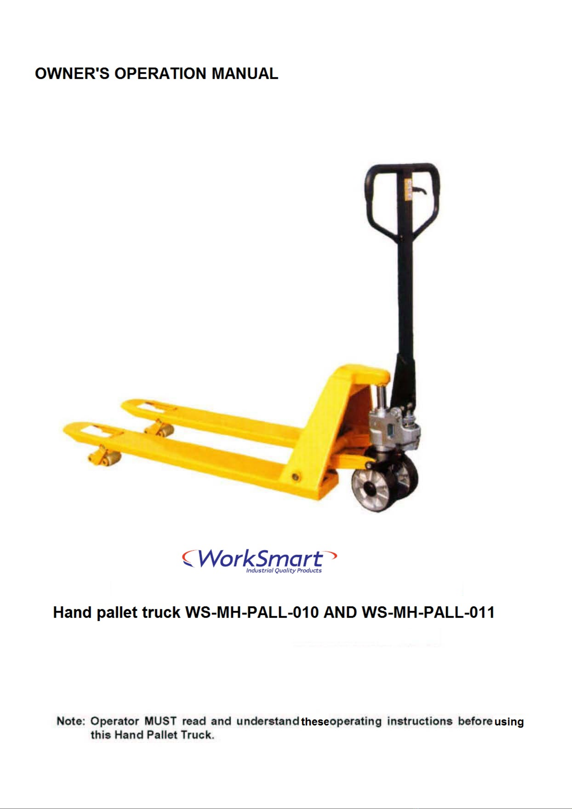
following way: move the control handle (G117) to the LOWER position, then move the draw-bar up and
down several times.
4.3 DAILY CHECK AND MAINTENANCE
Daily check of the pallet truck can limit wear as much as possible. Special attention should be paid to the
wheels, and axles, as thread, rags, etc. may block the wheels. The forks should be unloaded and lowered
in the lowest position when the job is over.
4.4 LUBRICATION
All bearings and shafts are provided with long-life grease at the factory. You should only need to provide
with long-life grease at monthly intervals or after each time the truck is cleaned thoroughly to the lubrication
points.
5 GUIDE TO SAFETY OPERATION
5.1 Operator should read all warning signs and instructions here and on the pallet truck before using this
truck.
5.2 Do not use on sloping ground.
5.3 Do not operate a pallet truck unless you are familiar with it and have been trained or authorized to do so.
5.4 Do not operate a pallet truck unless you have checked its condition. Give special attention to the wheels
and rollers, the draw-bar unit, the fork unit, the lever plate, etc..
5.5 To pull the truck, always move the control handle into the drive position. This makes the draw-bar easier
to move and depressurizes the pump section of the hydraulics. This preserves the hydraulic seals and
the valve components. A long service life can be expected.
5.6 Do not take up any people on the pallet truck.
5.7 The operator should use gloves for protection.
5.8 When the goods have been transported, all people should be away from the forks for 600mm.
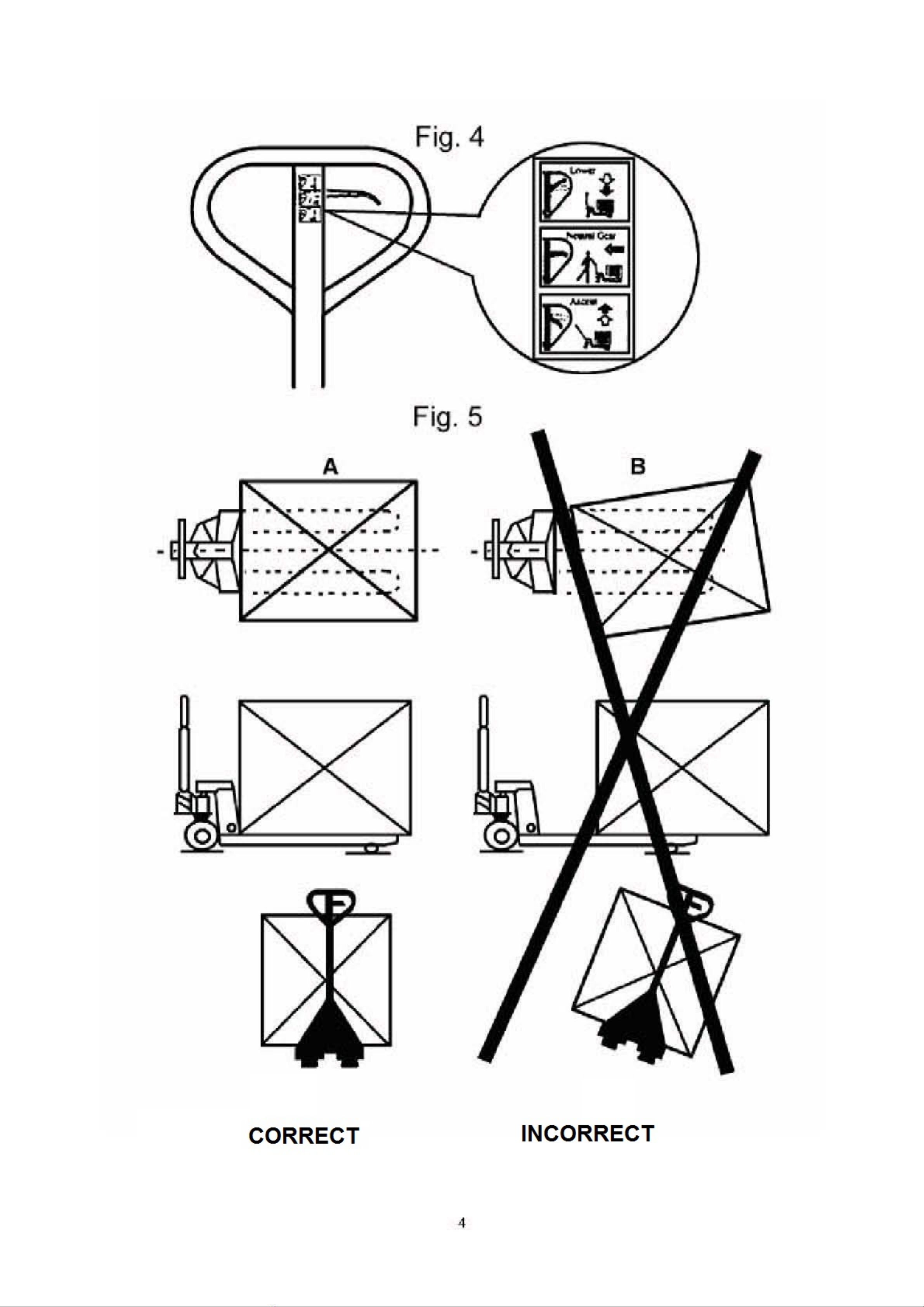
5.9 Do not load goods like fig. 5IB or load over maximum capacity.
6. TROUBLESHOOTING
No. Trouble Cause Fixing Methods
1 Forks won't raise
to max. height. -Not enough hydraulic oil. -Add hydraulic oil.
2 Forks won’t raise. -No hydraulic oil.
- The oil has impurities.
- The nut (G104) is too high keeping the pumping
valve open.
- Air has entered the hydraulic oil.
- Add hydraulic oil.
- Change the oil.
- Adjust the nut (G104) or
screw (318) see step 3.4
- Expel the air (see step 4.2)
3 Forks won’t lower -The piston rod(328) or pump((322) is deformed
resulting from partial loading slanting to one side or
over-loading.
-The fork was kept in the high position for a long time
with piston rod bared resulting in rusting and
jamming of the rod.
-The adjusting nut (G104) or screw (318) is not in the
correct position.
-Replace the piston rod (328)
or pump (322).
- Keep the fork in the lowest
position when not using and
lubricate the rod.
-Adjust the nut (G104) or screw
(318) (see item 3.3).
4 Leaks -Sealing parts worn or damaged.
- Some parts are cracked or worn. -Replace parts with new ones.
5 The fork descends
without the
release valve
working.
- Impurities in the oil are causing the release valve to
not close tightly.
- Some parts of the hydraulic system are cracked or
bored
- Air has entered the hydraulic oil.
- Sealing parts are worn or damaged.
- The adjusting nut (G104) or screw (318) are not in
the correct position.
- Replace with new oil.
- Inspect and replace the bad
parts.
- Expel the air (see step 4.2).
- Replace parts with new ones.
- Adjust the nut (G104) or
screw (318) see step 3.2.
NOTE: DO NOT ATTEMPT TO REPAIR THE PALLET TRUCK UNLESS YOU ARE TRAINED AND AUTHORIZED TO
DO SO.


This manual suits for next models
1
Table of contents
Other Work Smart Truck manuals