Worldcast Systems ecreso NEXT FM User manual

ecreso WorldCast Systems Group
web: www.ecreso.com - e-mail: contact@ecreso.com
NEXT FM
USER MANUAL
V.2.5.x
Date : 2010/11/26
Ecreso® is a registered trademark

NEXT FM, User Manual – 11/2010
Page 2
Head Office : Parc d’activites Kennedy - 20, avenue Neil Armstrong – F-33700 Bordeaux-Merignac (France)
TABLE OF CONTENTS
1. INTRODUCTION ..................................................................................................................................4
1.1.General information.....................................................................................................................4
1.1.1.About Ecreso..........................................................................................................................4
1.1.2.About the NEXT FM...............................................................................................................4
1.2.Before beginning .........................................................................................................................5
1.3.Licenses and options ..................................................................................................................5
2. PRODUCT PRESENTATION ..............................................................................................................7
2.1.List of accessories.......................................................................................................................7
2.2.Front panel ..................................................................................................................................7
2.3.Back panel...................................................................................................................................7
2.4.Description ..................................................................................................................................8
2.4.1.Inside the NEXT FM...............................................................................................................8
2.4.2.Synoptic .................................................................................................................................8
2.5.Technical Specifications..............................................................................................................9
3. INSTALLATION AND CONFIGURATION.........................................................................................11
3.1.Starting the equipment ..............................................................................................................11
3.2.Installing the dust filter ..............................................................................................................11
3.3.Connections ..............................................................................................................................12
3.4.Checking front panel LEDs .......................................................................................................12
3.5.Configuration using the front panel application.........................................................................13
3.6.Connecting to the network to access remote applications........................................................15
4. WEB SITE ..........................................................................................................................................17
4.1.Product Id’s ...............................................................................................................................17
4.2.Network .....................................................................................................................................18
4.3.Download ..................................................................................................................................19
5. MAIN APPLICATION PRESENTATION............................................................................................20
5.1.Introduction................................................................................................................................20
5.2.Launching the application .........................................................................................................20
5.2.1.From the front panel.............................................................................................................20
5.2.2.From the remote application ................................................................................................21
5.3.Accessing various functions......................................................................................................23
6. SYSTEM CONFIGURATION AND CONFIGURATION MANAGEMENT .........................................24
6.1.System configuration.................................................................................................................24
6.1.1.Product Identifiers ................................................................................................................25
6.1.2.Date/Time.............................................................................................................................26
6.1.3.Status ...................................................................................................................................27
6.1.4.Users....................................................................................................................................28
6.1.5.Network ................................................................................................................................29
6.1.6.PPP Dialout..........................................................................................................................30
6.1.7.PPP Dial-in...........................................................................................................................32
6.1.8.IP Router and Port translation..............................................................................................33
6.1.9.Support.................................................................................................................................35
6.1.10.SMTP Client mail .................................................................................................................36
6.1.11.SNMP Agent ........................................................................................................................37
6.1.12.Notifications..........................................................................................................................39
6.1.13.I/O Log .................................................................................................................................41
6.1.14.I/O Layout.............................................................................................................................42
6.1.15.I/O State ...............................................................................................................................43
NEXT FM, User Manual – 11/2010
Page 3
Head Office : Parc d’activites Kennedy - 20, avenue Neil Armstrong – F-33700 Bordeaux-Merignac (France)
6.1.16.Miscellaneous parameters ...................................................................................................44
6.1.17.Front panel ...........................................................................................................................44
6.2.Configuration management: backing up and restoring .............................................................45
7. TRANSMITTER CONFIGURATION ..................................................................................................47
8. AUDIO BACKUP MANAGEMENT ....................................................................................................48
8.1.Basic Audio Backup ..................................................................................................................49
8.1.1.Backup management ...........................................................................................................49
8.1.2.Status ...................................................................................................................................50
8.2.Advanced Audio Advanced .......................................................................................................51
8.2.1.Playlist Management............................................................................................................51
8.2.2.Playlist order ........................................................................................................................53
8.2.3.File transfer ..........................................................................................................................55
8.2.4.Stream Management ...........................................................................................................56
8.2.5.Parameters...........................................................................................................................57
9. RDS SETUP .......................................................................................................................................58
9.1.Encoder configuration ...............................................................................................................59
9.2.RDS Data ..................................................................................................................................61
9.2.1.DSN management................................................................................................................61
9.2.2.PSN management................................................................................................................62
9.2.3.DSN Parameters..................................................................................................................63
9.2.4.Main PSN Parameters .........................................................................................................67
9.3.ODA (Open Data Applications) .................................................................................................70
9.4.Enhanced RDS .........................................................................................................................73
9.5.UECP ........................................................................................................................................78
9.6.RDS Status................................................................................................................................80
10. VIEWING THE STATUS ..................................................................................................................82
10.1.Status ........................................................................................................................................82
10.2.Event log ...................................................................................................................................83
10.3.About… .....................................................................................................................................84
ANNEXE A : SOFTWARE OPTIONS....................................................................................................85
A.1. Full RDS ......................................................................................................................................85
A.2. Upgrade to 2 or 4 bands..............................................................................................................86
ANNEXE B : OPTIONAL INPUT / OUTPUT CONFIGURATION..........................................................87
B.1. Digital inputs ................................................................................................................................87
B.2. Relay outputs...............................................................................................................................89
B.3. Analog input module....................................................................................................................91
ANNEXE C : RDS ACCRONYMS .........................................................................................................92
ANNEXE D : FOR MORE INFORMATION............................................................................................94

NEXT FM, User Manual – 11/2010
Page 4
Head Office : Parc d’activites Kennedy - 20, avenue Neil Armstrong – F-33700 Bordeaux-Merignac (France)
1. INTRODUCTION
1.1. General information
1.1.1. About Ecreso
Founded in 1956 near Bordeaux, ECRESO was created by radio broadcasting enthusiasts and counts
today as one of the most important player on the international broadcasting stage.
Ecreso offers a line of analog and digital radio transmitters and digital television transmitters
(DVB-T/H, DAB, DAB+, T-DMB), low power or high power, either water or air cooled.
ECRESO is today part of the WorldCast Systems Group and as such, it proposes solutions for remote
control, audio measuring, sound processing, RDS encoding and transmission network monitoring.
1.1.2. About the NEXT FM
Research Program supported by the French Council of Aquitaine.
The Next FM is the first ‘All in One’ FM transmitter which includes digital audio processors, a stereo
encoder plus additional innovative features such as an RDS encoder, embedded audio backup, I/O
remote control and TCP/IP connectivity.
Ecreso’s innovative approach of combining a high quality transmitter with essential broadcast
functionality allows many savings to the broadcaster in terms of cost, real estate, time and energy.
The NEXT FM takes less space at the transmitter site, draws less power and is a highly competitive,
cost-effective alternative to purchasing a range of separate devices. With a single, integrated user
interface to control all functions, the NEXT FM also enables greater user efficiency.
Key features of the NEXT FM:
¾0.5, 20 or 100 W FM modulator and RF amplifier
¾Sound Processor: 1, 2 or 4 bands (software upgradeable in 2 or 4 bands)
¾Audio Backup
¾RDS Encoder
¾Stereo Encoder
¾Power backup system
¾I/O Remote control for a total solution
¾FM receiver for rebroadcasting and monitoring
Several applications, that can be launched from the Radio all in one portal or from the front panel, give
access to those functions, each with its own user manual :
¾Radio all in one: main application which includes RDS, audio backup, transmitter
configuration, unit status and system configuration.
¾Sound4 powered Digiplexer Sound Process: sound processing application,
¾ScriptEasy v.2.3.7 and MasterView v.1.3.1*: remote control and automation application
and creation of end-user views.
Whether remote or local, these applications work in similar ways.
Layout differences (login window, virtual keyboard) exist and are described in the applicable manual.
* Only the MasterView Viewer is available from the front screen application.
To ensure optimal performance, do not start 2 remote applications at the same time.

NEXT FM, User Manual – 11/2010
Page 5
Head Office : Parc d’activites Kennedy - 20, avenue Neil Armstrong – F-33700 Bordeaux-Merignac (France)
1.2. Before beginning
So as to preserve the safety of the devices and to ensure operations without danger, the user must
respect the following instructions, symbols and precautions:
1. The device should only be operated in the conditions described in this manual.
2. Nothing must obstruct the ventilation.
3. The device must only be used with a plug that incorporates a protective ground
contact.
4. To avoid any risk of electrocution, the protection conductor must not be cut,
intentionally or not, either on the device or on the power cord.
5. Before switching on the device, be sure that the nominal voltage specified on the
device corresponds to that of the mains’ nominal voltage.
6. To avoid any electromagnetic interference, the device must only be used when it
is closed. Shielded cables are mandatory.
7. The device should only be operated on a stable electrical network. If the electrical
network is not stable, a power conditioner, such as a UPS, must be used.
8. Any operation concerning maintenance, adjusting or repairing must be carried out
by qualified staff.
¾Caution: LITHIUM BATTERIES
If the battery is not correctly replaced, there will be a risk of explosion.
Only replace it with a battery of the same type. Contact Audemat before attempting to use
another type.
Do not throw away used batteries; send them back to us.
1.3. Licenses and options
Depending on the package you purchased, software and hardware options may be included;
otherwise, they may be or acquired.
¾Software options:
¾Full RDS:
Configure up to 10 DSN (on 2 in basic RDS),
Manage EON (up to 9 EON in addition to the main PSN per DSN),
Manage SLC,
Configure ODA.
¾Advanced Audio Backup: creation and management of embedded playlists that will
replace the analog or AES inputs in case they fail.
¾MasterView: with this application, visualize and control your site in custom views.
¾1 to 2-band upgrade.
¾2 to 4-band upgrade.
Please see Appendix A of this manual for upgrading procedures.
¾Hardware options:
¾Input / Output modules:
•Digital inputs: this module provides 16 digital inputs on a female SUB-D 25.
•Relay outputs: this module provides 8 relay closures on a male SUB-D 25.
•Analog inputs:this module provides 8 analog inputs on a female SUB-D 25.
Five slots are available on the NEXT FM, to set up to 4 digital input modules, up to 5
relay output modules and up to 1 analog input module.

NEXT FM, User Manual – 11/2010
Page 6
Head Office : Parc d’activites Kennedy - 20, avenue Neil Armstrong – F-33700 Bordeaux-Merignac (France)
¾Redundant power supply: in case one power supply fails, the other one takes over, thus
allowing the unit to operate with no interruption. Also includes a UPS (Uninterruptible
Power Supply) to make it possible to send an alarm in case of complete power failure.
Please see Appendix B of this manual for input / output configuration.

NEXT FM, User Manual – 11/2010
2. PRODUCT PRESENTATION
2.1. List of accessories
The following are included with the NEXT FM:
•1 power supply cable, or 2 with the “Redundant Power Supply” option
•1 crossed network cable (B)
•1 dust filter
•Fuses
•1 folder including 1 CD-Rom, 1 quick start, 1 I/O configuration notice, 1 sticker:
#2 for a 2-band NEXT FM or #4 for a 4-band NEXT FM, 1 quality control form.
2.2. Front panel
2.3. Back panel
With Redondant Power Supply option.
Page 7
Head Office : Parc d’activites Kennedy - 20, avenue Neil Armstrong – F-33700 Bordeaux-Merignac (France)

NEXT FM, User Manual – 11/2010
2.4. Description
2.4.1. Inside the NEXT FM
Sound processor
+ RDS encoder
+ Stereo encoder
Power
supply
Power supply
management
Hot swap fan
FM Exciter
0.5 W
20 W or 100 W
amplifier option
TX remote
control option
FM/RDS
receiver
Audio backup on
hard drive and
mother
board
Touch screen Flash card
Backplane card
2.4.2. Synoptic
AUDIO
INPUT RF
OUTPUT
Main power
supply
Synthesizer 0,5 W
Ampli
Harmonic
filter
Incident
reflected
power
detection
ALC
monitorin
g
LCD display
Digital sound
processing
and stereo
encoding
Monitoring
demodulator
Control
I/O
20 W or 100 W
amplifier option
Redundant
power supply +
UPS option
Auxiliary
input
Page 8
Head Office : Parc d’activites Kennedy - 20, avenue Neil Armstrong – F-33700 Bordeaux-Merignac (France)

NEXT FM, User Manual – 11/2010
Page 9
Head Office : Parc d’activites Kennedy - 20, avenue Neil Armstrong – F-33700 Bordeaux-Merignac (France)
2.5. Technical Specifications
Main features
Dimensions (WxHxD) 485 x 135 x 535 mm (3 U high)
Weight 14 kg
Operating temperatures
Nominal performance +5°C to +45°C
Storage -20°C to +70°C
Electrical specifications
Voltage 90 to 265 VAC. 47 to 63 Hz
Wattage consumption 70 W at 230 VAC with 0,5 W amplifier
100 W at 230 VAC with 20 W amplifier
320 W at 230 VAC with 100 W amplifier
Analog Input
Quantity 1 stereo
Level 2 ranges : +12 or +24 dBu jumper selectable
Impedance 600 / 10 kJumper selectable
Connector XLR female balanced and EMI suppressed
Digital Input
Quantity 1 stereo
Standard AES 3
Sampling Rate 44.1 to 192 kHz – 24 bits
Connector XLR female balanced and EMI suppressed
SCA/RDS input
Quantity / Connector 1 BNC female connector
Level +24 dBu, identical to the MPX output (adder)
Type Adder jumper selectable
Analog Output
Quantity 1 stereo
Level 2 ranges : +12 or +24 dBu Jumper selectable
Impedance Minimum load impedance 300 at +24 dBu
Connectors XLR male balanced and EMI suppressed
Digital Output
Quantity 1 stereo
Standard AES 3
Sampling Rate 44.1 to 192 kHz – 24 bits
Connector XLR male balanced and EMI suppressed

NEXT FM, User Manual – 11/2010
Page 10
Head Office : Parc d’activites Kennedy - 20, avenue Neil Armstrong – F-33700 Bordeaux-Merignac (France)
Stereo Generator Output
Quantity 1 output which can deliver MPX or 19kHz pilot (software
selectable)
Level 2 ranges : +6 or +18 dBu Jumper selectable
Impedance Minimum load : 35 at +18 dBu
Connectors BNC female – EMI suppressed
Audio Performances
Processing delay From 1.5 to 5.5 ms (depending on presets and audio path)
Frequency response
FM : 30 Hz – 15 kHz +/-0.2dB (de-emphasized measured on
analog output)
FmHQ : 30 Hz – 17 kHz +/-0.2dB (de-emphasized measured
on analog output)
HD : 30 Hz – 20 kHz +/-0.2dB (measured on HD output)
Noise <-90 dB (de-emphasized)
Distortion <0.02% THD (de-emphasized)
Separation >70 dB
RF Output
Power Adjustable 1-110 W or 1-22 W depending on version
Frequency 87.5-108 MHz, adjustable in 10 kHz increments
Spurious rejection * > 75 dBc within the 87.5 to 137 MHz band
> 70 dBc beyond
*non applicable to the 0.5 W version.
Frequency stability < 5 ppm/year
RF Output / Audio performances
Undulation < 0.25 dB
Distortion < 0.1%
Separation M/S < -55 dB
Crosstalk L/R > 45 dB
Residual AM < -60 dB
C/N Ratio > 65 dB

NEXT FM, User Manual – 11/2010
3. INSTALLATION AND CONFIGURATION
3.1. Starting the equipment
Page 11
Head Office : Parc d’activites Kennedy - 20, avenue Neil Armstrong – F-33700 Bordeaux-Merignac (France)
DO NOT PLUG IN THE UNIT.
!
1. Install the dust filter if the unit’s environmental quality requires it (see diagram next page).
2. Connect the transmitter RF output to a 50 ohm charge with a wattmeter (see connection diagram
next page).
The 50 ohm charge power to use depends on the transmitter power:
¾Greater than 2 W for a 0.5 W transmitter.
¾Greater than 30 W for a 20 W transmitter.
¾Greater than 150 W for a 100 W transmitter.
When you acquired your NEXT FM, the RF amplifier is deactivated and power is set to 0. These
settings will then be adjusted using the front panel application.
For safety reasons, always deactivate the amplifier and the power if the NEXT FM is not in
use.
3. Connect the inputs. The AES input is the default main source, but if the analog input is the only
connected input it will become the main source. Please read the sound processing manual for
input management.
4. Connect to power using provided cable (or cables with “Redundant power supply” option). Press
the reset button using an adjustment screwdriver.
3.2. Installing the dust filter
1. Using a phillips screwdriver, unscrew the 5 screws from the front panel so as to be able to
remove it.
2. Set de dust filter in front of the fan, with the grid towards the fan.
3. Screw the front panel back in place with the 5 screws.
Note: make sure the fan works properly after starting the unit. If not, the front panel might not be
properly screwed.

NEXT FM, User Manual – 11/2010
3.3. Connections
NEXT FM’s back panel
Audio/MPX
Inputs
Connect to power suppl
y
UECP COM ports
USB port for modem connection
(with USB-serial converter)
Slots for relay outputs and
digital inputs (option)
Connect to power supply (with
redundant power supply option)
Audio/MPX
Outputs
RF antenna output Network connection
for PC audio IP stream
Fans with 100 W
amplifier
RF amplifier
NEXT FM’s front panel
Page 12
Head Office : Parc d’activites Kennedy - 20, avenue Neil Armstrong – F-33700 Bordeaux-Merignac (France)
3.4. Checking front panel LEDs
LED blinks: unit is on. LED is on: 3 dB alarm on RF amplifier. 1
LED is on: main audio source is
available. LED is on: VSWR alarm on RF amplifier. 2
LED is on: secondary audio source is
available.
LED is on: power supply unit fault (only
with redundant power supply option). 3
LED is on: PLL locked. LED is on: communication issue with the
sound processor. 4
LED is on: local mode is on, a remote
user cannot connect to the unit.
LED is on: switch for main audio source to
secondary audio source.
or sticker to place on the front panel
RF monitoring output
Headphone output
Crossed cable (B) for
direct connection to PC
USB port for
keyboard connection

NEXT FM, User Manual – 11/2010
1 The 3 dB alarm is triggered on threshold overshoot as set on the transmitter page (see section 7).
This alarm indicates a problem with the amplifier or at the output. Check the antenna and cables which
can be unplugged or defective.
2 The VSWR alarm is triggered on threshold overshoot as set on the transmitter page (see section 7)
or when the unit goes into hardware protection mode when the VSWR is too high. This alarm indicates
a problem with the amplifier or at the output. Check the antenna and cables which can be unplugged
or defective.
3One of the PSU is not working. Check the main supply.
4If the Warning LED blinks when the main power is back on, it indicates that the unit is powered by the
UPS (“Redundant Power Supply" option) but has not started yet. Simply use the “Reset” button on
the front panel to restart the unit.
If the Warning LED is on, please contact the support department.
3.5. Configuration using the front panel application
The front panel screen gives access to the NEXT FM’s
various applications; however, it is first used to configure the
unit.
1. The front panel screen displays the status page which
gives an overview of the main functions (transmission,
RDS, audio backup…).
2. In order to be able to configure the NEXT FM, establish
the connection by touching the last icon with the
stylus.
3. Default login and password are Admin / admin (case
hen the cursor is in a text box, a keyboard
sensitive).
W
automatically appears. Enter the value and touch
ENTER to validate and hide the keyboard. Additional
characters keyboards are available with the <> key.
Y ncou may also connect in local mode for maintena e
purposes (default password: 1234). Remote connection
is then deactivated.
4. Once connected, the RDS application is displayed.
Default language is English.
5. Should you wish to switch t ch, touch the System
icon.
o Fren
Page 13
Head Office : Parc d’activites Kennedy - 20, avenue Neil Armstrong – F-33700 Bordeaux-Merignac (France)

NEXT FM, User Manual – 11/2010
Page 14
Head Office : Parc d’activites Kennedy - 20, avenue Neil Armstrong – F-33700 Bordeaux-Merignac (France)
d choose the
language in the scroll-down menu. Click “Update”.
plication needs to restart for the changes to take
effect so you will be disconnected and you will have to
connect again.
6. Select “Application” in the menu an
7. The ap
8. Click the System icon in the tool bar
to access system settings.
9. Select “Network” in the menu, modify values if
necessary using the touch screen. Use ENTER to hide
the keyboard.
LTwo network connectors are availab
front panel connector is recommended fo
recommended for a network c
le, one on the front panel, the other on the rear panel. The
r a direct connection; the back panel connector is
onnection or audio IP stream.
es. .
ation:
11. Touch
10. Touch the “Update” button to lock in your chang
Transmitter configur
to enable the RF transmitter and set up
12. Touch the Save icon
its frequency and power.
.
13. Return to the login scree
panel” page of the system
n to disconnect. An automatic disconnection time can be set on the “Front
configuration.
n:
ng the “System” icon and the “Shutdown equipment”
button.
and connect the antenna to the transmitter RF output.
the Reset button on the front panel.
For a more advanced configuration, use the remote applications (see below section 3.6) or
14. You just finished setting your NEXT FM for basic use. Now, you ca
¾Turn off the NEXT FM by clicki
¾Disconnect the load
¾Start the unit using
the front panel application.

NEXT FM, User Manual – 11/2010
Page 15
Head Office : Parc d’activites Kennedy - 20, avenue Neil Armstrong – F-33700 Bordeaux-Merignac (France)
.6. Connecting to the network to access remote applications
d the
* or a le (not provided) for a LAN connection, preferably on the back panel IP
2.
range as the IP address you just set using the front panel application, so both are compatible.
E
r
•For this, if using Windows 2000 or Windows XP, click the “Start” button and:
¾Control panel/Network connections/
¾Local Area Connection / Properties
, click the “Start” button and:
sk
).
3. nloa
er, M
re: "Admin"/"admin
3
1. Connect network cable B for a direct connection * between your PC an NEXT FM IP
connector.
straight cab
connector.
In case you are using a direct connection, you will need to set an address on the PC in the same
xample: if the NEXT FM’s IP address is 172.17.2.35, the PC address must be in the 172.17.2.xx
ange.
¾Click on Internet Protocol (TCP/IP) in the scroll-
down menu then on “Properties”.
¾Add the IP address and the sub-network mask.
(for example 172.17.2.56/ Netmask 255.255.0.0)
•With Vista
¾Control panel / Network and Internet / Network and
Sharing Center.
¾Click on “View Status” for your local area connection,
and on Properties
¾Click on Internet Protocol 6 or 4 depending on your
network, then on Properties.
¾maAdd the IP address and the sub-net
(for example 172.17.2.56 / Netmask 255.255.0.0
The installation portal for the remote applications can be dow
embedded web site Open your web browser (Internet Explor
address you set using the front panel.
ded from the NEXT FM
ozilla…) and enter the IP
" (case sensitive).In both cases, default login and password a

NEXT FM, User Manual – 11/2010
Page 16
Head Office : Parc d’activites Kennedy - 20, avenue Neil Armstrong – F-33700 Bordeaux-Merignac (France)
4. Navigate to the “Download” page.
5. Click on “Application portal installer”, select "Open" to install directly the installation portal or
"Save" to install from the hard drive (recommended option). Once saved, launch the installer and
follow the wizard’s instructions.
. The installation portal will appear:
1. To launch one of the applications use desktop shortcuts or go to ‘Start’ Æ‘Programs’ Æ‘Audemat’
Æ‘Radio all in one’. Note: the Digiplexer Sound Process application can be launched from the
Radio all in one application.
9. If Windows Firewall is activated, add these applications to the list of approved applications.
6
7. Click on “Install applications” to start installing
all the applications for the NEXT FM:
>Radio all in one, main application:
transmitter configuration, RDS
application, audio backup and system
configuration.
>Digiplexer Sound Process: sound
processing and input management
application,
>ScriptEasy: remote control functions
>MasterView: end-user viewing tool.
8. Follow the wizard’s instructions.

NEXT FM, User Manual – 11/2010
Page 17
Head Office : Parc d’activites Kennedy - 20, avenue Neil Armstrong – F-33700 Bordeaux-Merignac (France)
4. WEB SITE
4.1. Product Id’s
¾Set:
oProduct name: this name can be use It
is therefore recommended to use a uniq
oProduct description
Both of these settings are optional better identify
the unit on the network.
number
Software version
LWhen making changes you must click on the “Update” button before leaving the page to lock in
your changes.
d when connecting with the remote application.
ue and easily identifiable name.
and at the user’s discretion, but useful to
¾View :
oNEXT FM serial
o
oHardware version

NEXT FM, User Manual – 11/2010
Page 18
Head Office : Parc d’activites Kennedy - 20, avenue Neil Armstrong – F-33700 Bordeaux-Merignac (France)
4.2. Network
•IP co
¾Ethernet configuration mode
lication can be configured for use with a static or dynamic IP address (DHCP).
DHCP mode is only recommended if the IP address given by the server is know (for instance if
MAC address).
ration
If using a static IP address, enter the parameters in this window.
¾DNS Servers: DNS configuration.
¾Current network status: current network parameters.
LWhen making changes you must click on the “Update” button before leaving the page to lock in
your changes.
nfiguration definition:
The app
L
the server gives an IP address to the
¾Static Ethernet configu
LReminder: The primary interface is in the back of the unit, the secondary interface is in front.

NEXT FM, User Manual – 11/2010
4.3. Download
This page enables you to download the installer software for using the NEXT FM applications. The
installer will install:
¾Radio all in one: main application for Transmitter Configuration + Audio Backup +
System Configuration + Unit Status + RDS Configuration .
¾Digiplexer Sound Process: sound processing application.
¾ScriptEasy: configuration of remote control functions.
¾MasterView: visualization and control of your site in custom views.
lick on “‘All- in-on installer” one installer’, and select ‘Open’ to install the application, or "Save" to
e hard drive (recommended option). Follow the wizard’s instructions.
Refer to the rmation.
C
install from th
manual for each application for more info
The NEXT FM MIB (Management Information Base) may also be downloaded from this page.
Page 19
Head Office : Parc d’activites Kennedy - 20, avenue Neil Armstrong – F-33700 Bordeaux-Merignac (France)

NEXT FM, User Manual – 11/2010
5. MAIN APPLICATION PRESENTATION
5.1. Introduction
The main re
¾
¾Tran
¾RDS
¾
¾Status and logs,
¾The Digiplexer Sound Process application.
Most functions are available both from the remote application and front the front panel application.
unctionality and usage differences are outlined in the manual when applicable.
the application
he application is available from the front panel or as a remote PC application. Page set-up might be
5.2.1.
mote application gives access to:
System configuration,
smitter configuration,
configuration,
Basic or advanced Audio backup management,
F
5.2. Launching
T
slightly different; however functions are identical in both versions.
From the front panel
1
Touch the connection icon to identify yourself (1).
Enter the login and password (2).
With standard login, default values are “Admin” / “admin” for an administrator and “Guest” / “guest”
for a simple user.
2
3
4
Page 20
Head Office : Parc d’activites Kennedy - 20, avenue Neil Armstrong – F-33700 Bordeaux-Merignac (France)
Table of contents
Other Worldcast Systems Measuring Instrument manuals

Worldcast Systems
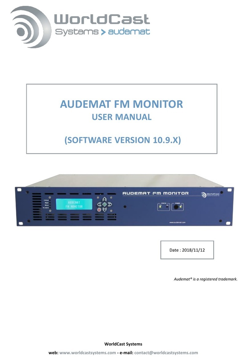
Worldcast Systems Audemat FM Monitor User manual

Worldcast Systems
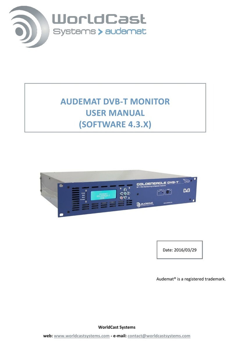
Worldcast Systems Audemat DVB-T Monitor User manual

Worldcast Systems
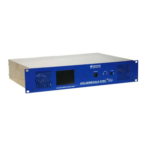
Worldcast Systems audemat GOLDENEAGLE ATSC User manual

Worldcast Systems
Worldcast Systems Audemat FM Monitor User manual

Worldcast Systems
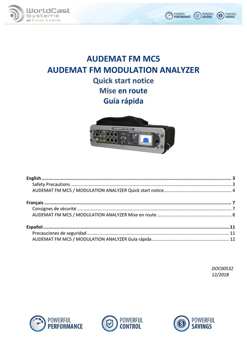
Worldcast Systems AUDEMAT FM MC5 User manual

Worldcast Systems
Worldcast Systems AUDEMAT FM MONITOR Silver User manual